| John Broskie's Guide to Tube Circuit Analysis & Design |
13 June 2023 Post Number 582
Recently, I attended a backyard party, filled with college professors and business folk. Artificial intelligence (AI) was a hot topic. Everyone was worried. Everyone had at least played with AI. Two or three of those in the conversation used AI assistance daily—and could not imagine not using it. Apparently, those who either hate or fear writing are in heaven, as AI does a better job than they can. And an artist there uses AI to create images based on her suggestion that she then did over in her own style. I warned that AI can not only steal text and images, but also make up "facts." Apparently, the "correct" term in regards to AI is "hallucination" (or confabulation or delusion). AI doesn't so much make up stuff, but fills in with stuff that it concludes should exist.
By the way, I have been waiting for my prediction from the early 1990s that computer operating systems would one day be replaced by personalities of famous people, such as Albert Einstein or Marilyn Monroe or Eddie Murphy. Eventually, I will get my Bertie OS (Bertrand Russell). Just feed an AI all 98 books by Russell and overlay his personality atop a workable operating system, and I will be happy. Last month, I asked Google's Bard a few questions. Q. Is the circlotron power amplifier necessarily a class-A amplifier? Bard.
Yes, Bard gets things right and wrong within the same answer on the same topic. It also gives you alternative answers. Here are a few morsels from its alternative stabs at the truth:
Q. Who is John Broskie and what does he have to do with audio?
At the party, I was asked my opinion of Bard. My reply was that since Bard thinks the world of me, it would be uncharitable of me to think less of it, even if it makes shit up. For example, I haven't written any books. No doubt I should have, but I haven't.
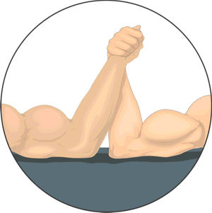
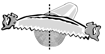
Constant-gm Darlington Recently, I wondered if I could force some auto-bias action upon an anti-2gm (i.e. constant-gm) output-stage design I had come up with a decade ago. While tweaking the circuit, I added two large-valued capacitors to shunt two diodes. Interestingly enough, these capacitors created an ever-on output stage, where the two output transistors never ceased to conduct some current. In other words, the capacitors had set in place a current floor, below which the output transistors did not go. No, I didn't invent class-A operation the cheap, which some amplifier makers have sought to do in decades past. Real, honest-to-God class-A operation means more than just nonstop current conduction; it also means that both output devices present an equal grab on the output signal. In contrast, a flat-line constant-current draw over half the sinewave cycle does nothing to improve the waveform fidelity, as the flat-lining turns the output device into a constant-current source. Think of push-pull class-A operation as two strong men arm-wrestling, with neither ever decisively winning, as their clasped hands swing closer to one side and then to the other. Another equally sexist—and equally useful—analogy I have made is that of two men sawing down a tree with a single two-handed saw.
In this analogy, class-A operation occurs when both men work equally. Class-B operation would ask that each man only pull the saw towards himself, but not push it away from himself. Imagine if one man were to pass out after having pulled the saw to his chest, but remained clutching the saw handle as the other pull the saw towards him, thereby having both to saw the trunk and pull the dead weight of the unconscious partner. Well, that is what happens when one output device goes into flat-line current conduction: it becomes a dead weight. Our concern has been with low-distortion output that is achieved with balanced push-pull operation, which flat-line current conduction does not necessarily not aid. Could it aid in linearizing the output stage? It certainly might in tube-based output stage, as the flat-line current conduction would force a higher idle current, which would move the tube's current swings away from the gooey bottom of its plate curves. In addition, the flat-line current conduction would aid in avoiding solid-state turn-on and turn-off switching glitches. In the special case of output power MOSFETs, it also avoids big changes in input capacitance, as the MOSFET's input capacitance is nonlinear, as it varies with being turned off and being turned on. Before showing the circuit, however, we need to review the Darlington pair of transistors.
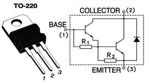
Darlington Pair
This two-transistor arrangement acts like a single transistor, and is often packaged as a single transistor, such as the BU941ZT and TIP122.
Darlington pairs made from discrete transistors or single-packaged, however, are not as popular as you might expect in audio electronics, as they carry some disadvantages. For example, they are typically slower than single transistors and can prove noisier. Noise is seldom and important issue in solid-state output stages, but switch-on time is important. With the two transistors in series, the first must turn on first before the second can conduct. In addition, the single-packaged Darlington pairs run into the problem of both internal transistors getting equally hot, which doubles the temperature-induced change in bias voltage. Most importantly, the Darlington-based output stage has been replaced by the following design.
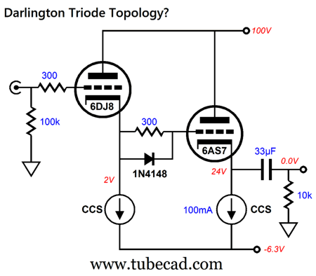
Transistors Q3 & Q4's shared emitter 100-ohm resistor and "speed-up" capacitor work to greatly reduce switching distortion. Of course, if the Darlington pair never turns off, we needn't worry about switching distortion, which explains why the Darlington pair is often used in a solid-state power amplifier's VAS stage; in this schematic, transistors Q1 & Q2 form the VAS stage. On the other hand, if power MOSFETs didn't exist, the Darlington pair would be far more popular, due to their ultra-high current gain and high input impedance. In general, I have avoided using the arrangement in audio designs—unless, of course, I had no better choice. Here is an interesting question: have you ever seen a "Darlington" arrangement made up of two triodes in series, i.e. a cascade of cathode followers? I don't believe I have, and I have seen a lot of schematics. Perhaps the following design might be of some merit. Since a triode's grid, unlike a transistor's base, doesn't draw current under normal operation, what would be the point? Well, what about under not normal operation? Let's say that the 6AS7 triode's grid is driven positive, so instead of presenting a near infinite load the preceding 6DJ8-based cathode follower, it presents a relatively low impedance. The 6AS7's 300-ohm grid-stopper resistor is bypassed with the signal diode so that voltage drop across the resistor is limited to the diode's forward-biased voltage (about 0.7V). Of course, at some positive input signal voltage, the 6DJ8's grid will also become positively biased to its cathode. Nonetheless, the cascading of cathode followers greatly extends the positive-input-voltage limit. Okay, enough overview. If you are a long-time reader, you will know that I have brought up the topic of gm-doubling distortion since at least the year 2000 and, starting in 2009, I have developed solutions, such as tacking on a pair class-C output devices to a class-AB output stage or to use commutating/switching diodes to increase the output device's effective gm once the pair leaves class-A operation. Another workaround I came up with was to pre-distort (or pre-treat) the input signal the output devices saw, which halved their gm while the pair operated in class-A mode, but allowed full gm once they broke out of class-A window of operation. In post 331 , we see the following implementation of pre-distorting.
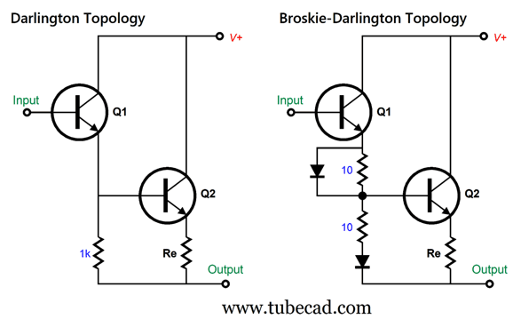
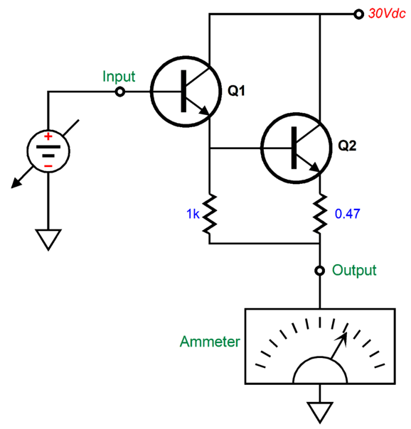
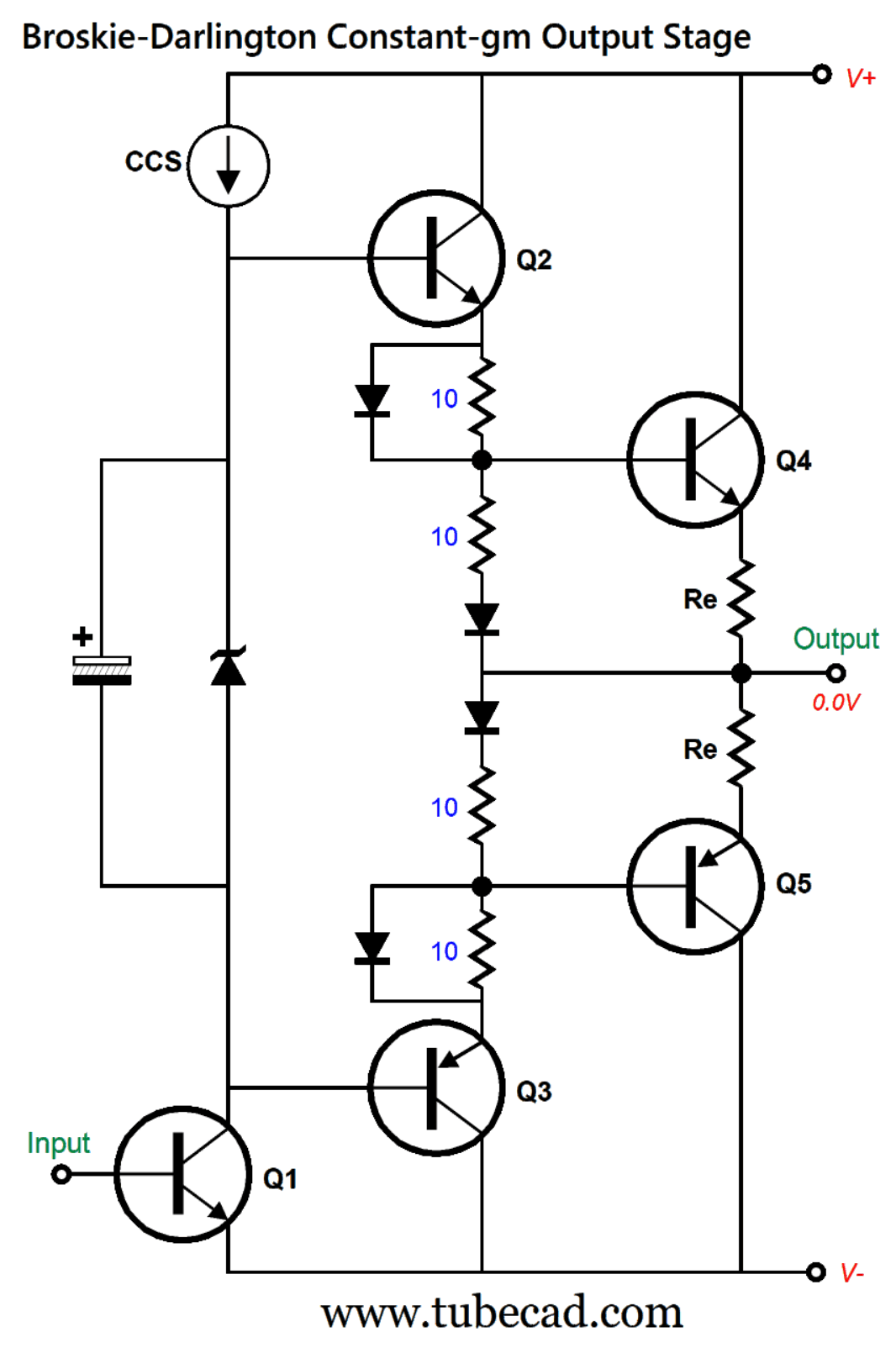
From post 331, "Note how we added an equal-valued second resistor and a zener diode. The two resistors define a two-resistor voltage divider, with a 50% signal reduction up to the point when the rectifier becomes forward biased, which allows 100% of the signal to pass through. This configuration allows the output transistors to retain all of their transconductance and yet allows the output stage as a whole to exhibit a constant transconductance." We can drive the input circuit with two emitter followers, which create a Broskie-Darlington topology. Transistors Q2 & Q3 drive the resistors and diodes. If we carefully select voltage relations in this circuit, we end up with a constant-gm output stage. Let's compare this Broskie-Darlington topology to the conventional Darlington. Note that the conventional Darlington's input transistor, because of the 1k emitter resistor, draws very little current at idle and can contribute little output current flow into the external load. In contrast, the input transistor of the Broskie-Darlington topology does draw a healthy amount of current (about 30mA) and can deliver over 100mA into loudspeaker. In other words, a robust input transistor is needed. Now, let's compare the DC transfer curves, starting with the conventional Darlington. This the SPICE setup, where input voltage is varied from 0Vdc to 3Vdc, which results in the following current-conduction plotline. At about 0.9Vdc, the conventional Darlington circuit begins to conduct, starting with Q1, then Q2. Now, let's run the same SPICE simulation with the Broskie-Darlington This is not the graph I originally got; in spite of the bypass capacitor getting an initial charge voltage of 0.544Vdc, the circuit never current flat-lined in simulations, as the SPICE engine ignores the capacitor charge in DC-transfer tests. My workaround was to replace the capacitor with a voltage-source of 0.544Vdc. We often have to employ this sort of "cheat" in SPICE simulations. In this case, an audio power amplifier is expected to only amplify AC signals, not DC voltages, but the SPICE DC-transfer simulation cannot "see" the capacitors, as the capacitor is an open circuit to DC simulations. The second plotline shows the amount of current flowing through the top diode. In other words, it reveals when the diode reaches its forward-bias voltage and it begins to conduct and reveals the voltage limit to the voltage drop across the top 10-ohm emitter resistor. Here is a close-up of the diode plotline. We see that at about 1.9V of input voltage, the diode engages. When the diode engages, the two-resistor voltage divider made up of the two 10-ohm emitter resistors, no longer halves the input signal; instead, the diode relays 100% of the signal to transistor Q2's base. In other words, we have created a two-gm (two-slope) Broskie-Darlington. Here is the graph with extended lines to show the two slopes and their inflection point. Inspecting the two-slope line, we see that an output stage based on the Broskie-Darlington should idle at about 400mA to 450mA. Putting together an output stage based on the Broskie-Darlington is easy enough. To test this output stage's linearity in SPICE, the load was lowered to 1 ohm.
If we remove two diodes, the OPS transforms into conventional Darlington of sorts.
We can readily see the two slopes that results from the gm doubling in the middle. With 45W of output into an 8-ohm load, we see the following current swings through the two output devices.
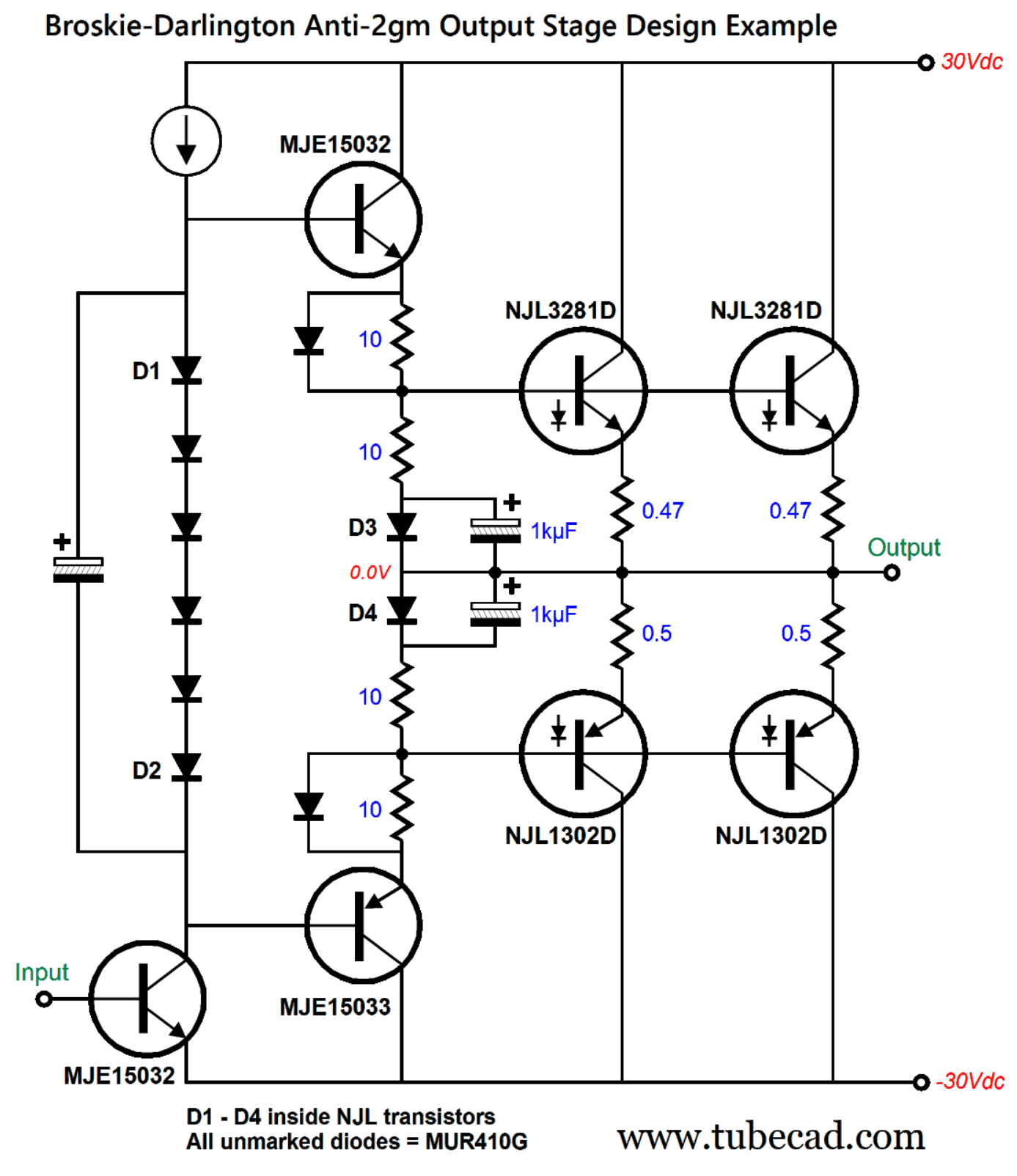
Making the Broskie-Darlington into an auto-biased OPS requires using the complementary ThermalTrak™ transistors, NJL3281D (NPN) and NJL1302D (PNP).
These On Semiconductor power transistors come in a five-pin TO-264 package and each contains an electrically isolated, but thermally connected diode. As the transistor heats up, its base-to-emitter voltage drops, but so, too, does the diode voltage drop. Unlike attaching a thermal-tracking transistor to the heatsink that suffers from long thermal time lags, the diode's change is near instantaneous.
Since four diodes are needed, the output stage holds four ThermalTrak™ output transistors. Note the 1kµF shunting capacitors across diodes D3 & D4. In SPICE simulations, the output stage experienced a slight negative thermal shift of -12mA per 10C degrees increase in temperature. Reality may differ, as the assumption here was that the driver transistors would get their own relatively large heatsinks. With an 8-ohm load and 45W of output and no negative feedback, the output stage's distortion was below 0.1%. None of the two main output transistors ever draw less than 60mA each through the entire waveform. If we subtract the "Broskie" from this circuit, leaving only the "Darlington," the distortion climbs to 1%. With 1W of output, the distortion harmonic cascade has a lovely single-ended flavor and the THD is below 0.01% in SPICE simulations.
Not bad. Add a tube-based line-stage amplifier with a strong 2nd-harmonic flavor, and we are were we want to be. In SPICE simulations, this arrangement resulted in a slight negative thermal effect on the idle current, where an increase of 100 degrees C produced a 65mA drop in idle current. This assumed big and separate heatsinks for the two driver transistors. In reality, we might see no change in idle current or a slight positive change.
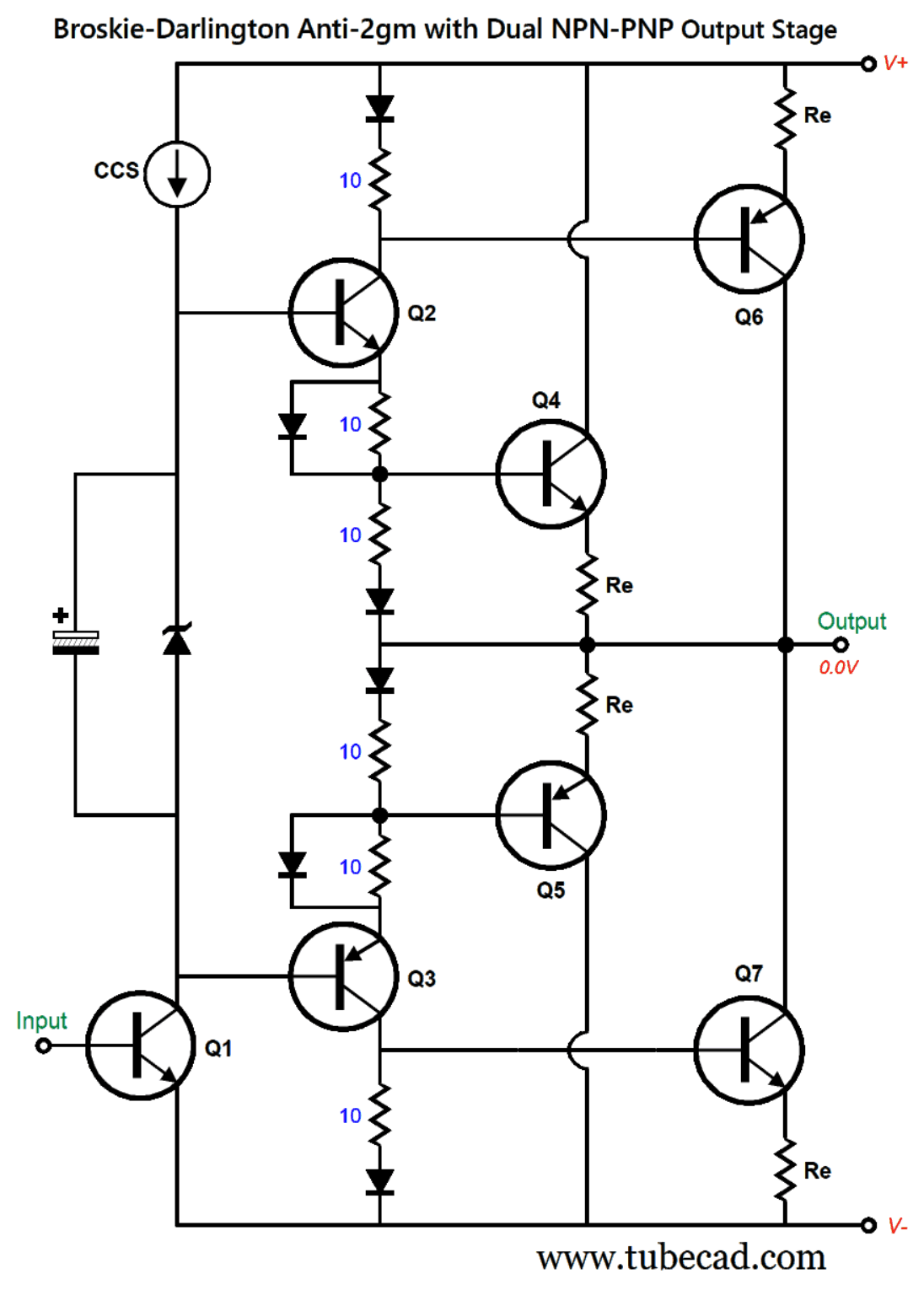
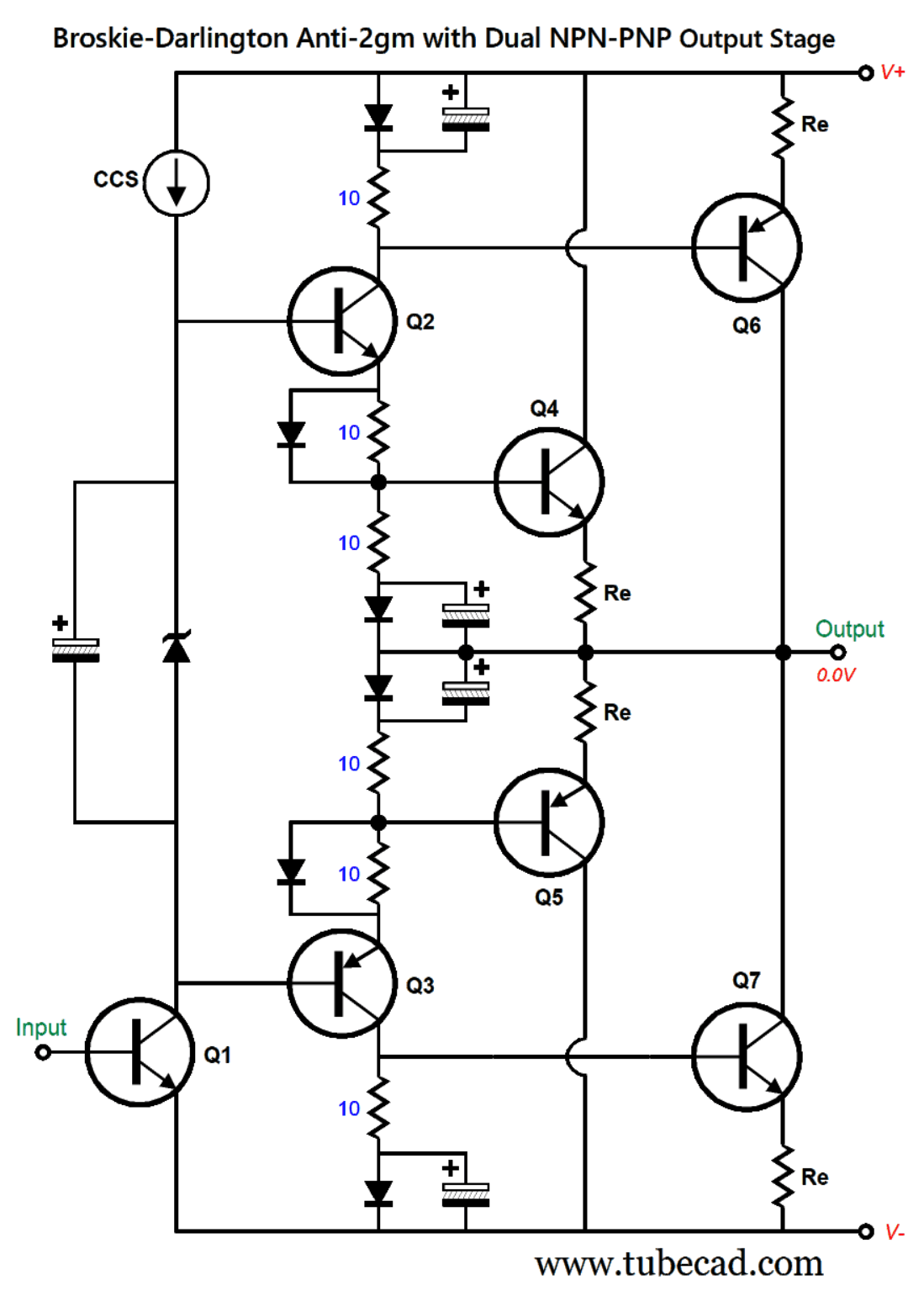
Broskie-Darlington Anti-2gm with Dual NPN-PNP OPS
Note the top and bottom diodes and the top and bottom 10-ohm collector resistors. These are enough to have transistors Q4 through Q7 on at idle. Next, we add the big shunting capacitors that create a floor to the output transistors' current conduction.
Note the added capacitors at the top and bottom. Without these capacitors, transistors Q6 & Q 7 would cease to conduct. While this topology is certainly interesting, no real improvement was seen in SPICE simulations. Perhaps, reality might prove more generous.
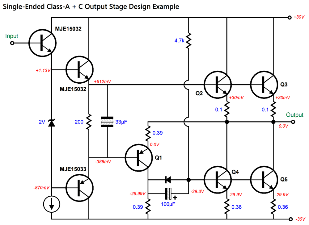
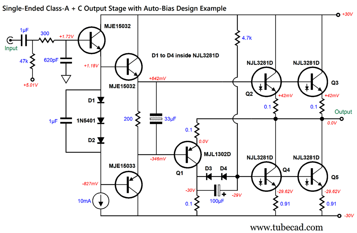
Single-Ended Class-A + C Push-Pull Output Stage Since I was on a roll with the previous output stage that holds four ThermalTrak™ output transistors, I decided to pull out an old design from post 333 , as it seemed a good candidate for auto-bias. (See post 364 for other Class-A + C push-pull output stage designs.)
The output stage runs in a single-ended fashion, as transistor Q3 is turned off at idle and only switches on when the output current swing exceeds the class-A window. Thereafter, the output stage converts to push-pull operation, as transistor Q3 conducts and Q5 shifts from being a constant-current source to being an actively driven output device. Yes, this is a double hybrid, as it combines single-ended with push-pull, and it uses both class-A and class-C operation.
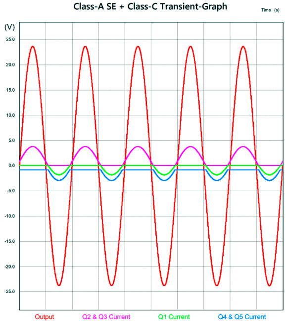
The SPICE-generated transient graph shows how transistors Q4 & Q5 never turn off, while Q1 is completely turned off at idle.
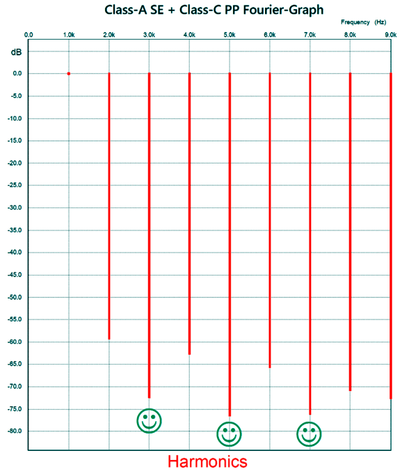
With 36W of power output at 1kHz, the Fourier breakdown of the harmonics produced in SPICE simulation is glorious to behold. Note how the 3rd, 5th, and 7th harmonics are lower than the even-order harmonics—the exact opposite of 99.99999% of push-pull output stages.
What our ears long to hear is the following:
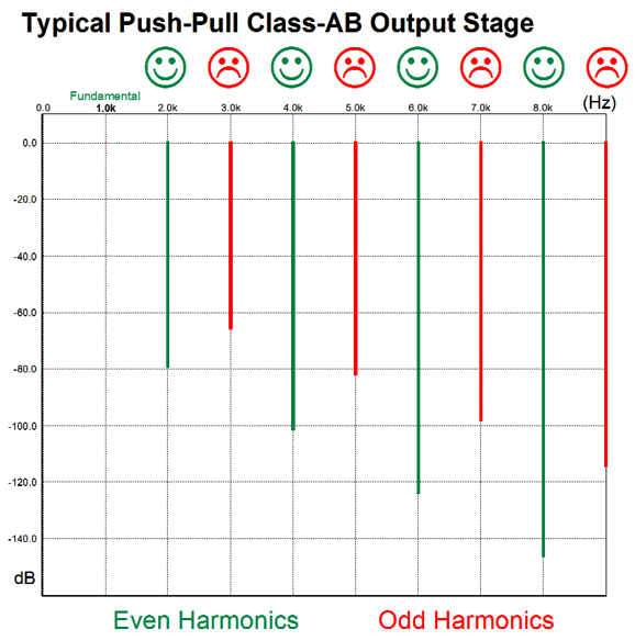
This sadly rare harmonic structure is the antidote for ho-hum audio playback. The huge mistake most audiophiles make is to believe in flat-line output and in The Absolute perfection.
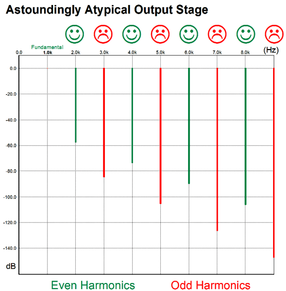
Absolute-Sight eyeglasses must hold perfectly flat lenses, which makes sense if you have perfect vision. Of course, if you have perfect vision, then you don't need glasses at all. The recorded music we hear is as far from perfect as canned soup is from five-star restaurant soup. All along the audio chain the signal enters and exits the typical high NFB, push-pull amplifiers, with each pass through adding odd-order harmonics. When poisoned, we seek an antidote. The astoundingly atypical harmonic structure is not perfect, but it is absolutely desirable, just as real non-flat eyeglass lenses are. (See post 480 for more on this topic.) To make this circuit auto track thermal changes requires four diodes that are entrapped within four output transistors.
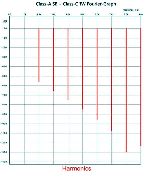
Diodes D1 through D4 are located with the four NJL3281D ThermalTrak™ output transistors. The MJL1302D power transistor is an equally robust transistor, and it will also deliver current into the loudspeaker, but only when the output voltage swing requires it. Compare this schematic to the previous one and you will see that two diodes D3 & D4 in series required a change in the bottom NJL3281D emitter resistors have been increased to 0.91 ohms, while the MJL1302D's resistors have been reduced to 0.1 ohms. With 4Vpk at 1kHz (1W) into an 8-ohm load, the distortion harmonic structure is wonderfully single-ended in flavor:
Mind you, there is no negative feedback loop to reduce distortion. The THD is a bit higher than 0.1%. The current conduction is interesting.
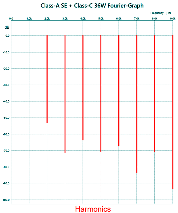
Note that transistor Q1 draws no current, while Q4 & Q5 come close to presenting a constant-current flow. Okay, let's examine the other extreme, 36W, 24Vpk at 1kHz.
Once again, we witness the same astoundingly atypical harmonic structure. How well does the auto-biasing work? Not bad.
The output stage's idle current rises slightly from 20 degrees C to 47 C, then falls off. Just about perfect.
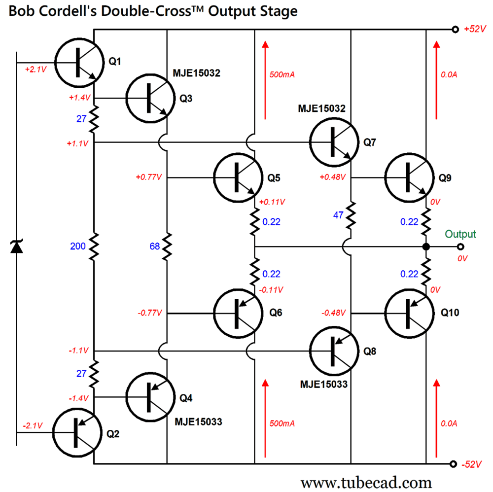
Bob Cordell's Double-Cross™ Output Stage In Cordell's second edition (2019) of his essential audio-electronics book, Designing Audio Power Amplifiers, he presents his version of a constant-gm output stage. The primary pair of output transistors Q5 & Q6 run hot at idle (0.5A), while secondary pair of output transistors Q9 & Q10 are turned off. When the primary pair exceeds 1A of output current flow (4W into 8 ohms), the secondary pair switch on, thereby maintaining a constant output-stage transconductance. Transistors Q3 & Q4 along with Q6 & Q7 are the driver stages. The three resistors, 27 and 200 and 27 ohms, set the voltage division needed to stagger the turn-on timing of the secondary pair of output transistors. What do I think of Cordell's Double-Cross™ output stage?
Amazingly enough, I am reminded of what the great German mathematician, Carl Friedrich Gauss, said of Johann Bolyai’s bold new work on non-Euclidean geometry, Appendix, in a letter to Bolyai's father, written on March 6, 1832:
Two years before Johann Bolyai published his Appendix and unknown to both Gauss and Bolyai, the Russian mathematician, Nikolai Lobachevsky, published the first paper on non-Euclidean geometry. Eventually, Gauss saw a German translation and, in a letter Schumancher, said the following:
The mistake Gauss made is the same one made by Newton and Darwin: he kept his work a secret. Isaac Newton creates Calculus, but does not reveal it the world; later, Gottfried Wilhelm Leibniz invents it on his own and publishes first, which partially explains why we use his notation, not Newton's. Darwin got scooped by Alfred Wallace , which forced Darwin to abandon the book he was writing at the time and get cracking on his On the Origin of Species.
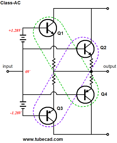
I didn't make the same mistake, as in 2009 my post 177 revealed the Class-AC output-stage arrangement, wherein a secondary pair of output devices are not conducting at idle and only turn on once the class-A window of output current swing is exceeded by the primary set of output devices. From post 177:
Transistors Q2 & Q4 are completely turned off at idle and only turn on once their partner opposing transistor ceases to conduct. As long as transistors Q1 & Q3 continue to conduct, the output stage operates in class-A. So, what do I think about Cordell's output stage? If I begin with the statement that I dare not praise such a work, you will of course be startled for a moment: but I cannot do otherwise…
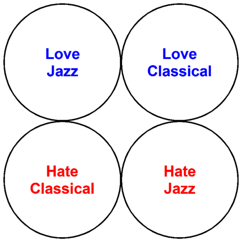
Music Recommendation: The Great European Songbook Who will like this album? Let's assume that we can divide listeners into the following groups.
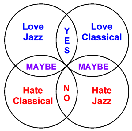
Next, as a nod to those who love Venn diagrams, we examine the intersections.
This reminds of the similar diagram for when only one parent has a genetic disease and four children. The odds are that one child will also be inflicted, but one will be totally free of it, while two will be carriers who do not succumb to the ailment. Of course, strict logic seldom applies to human affairs. For example, I once knew an English woman, who when given a choice for a diluent for her coffee, chose half-and-half over milk, cream over half-and-half—but milk over cream. Was she illogical? If so, how?
In a similar fashion, I can imagine someone, who dislikes both classical music and jazz, liking this album, finding that the music undoes those aspects of each genre that proved undesirable. Perhaps, classical was deemed too tight; jazz, too loose. Both Amazon Music and Qobuz offer the album in 24-bit, 48kHz. (By the way, Chesky and I are the same age and I once met him in an elevator at an audio show. He seemed an extremely likeable guy.)
//JRB
Did you enjoy my post? Do you want to see me make it to post 1,000? If so, think about supporting me at Patreon.
User Guides for GlassWare Software
For those of you who still have old computers running Windows XP (32-bit) or any other Windows 32-bit OS, I have setup the download availability of my old old standards: Tube CAD, SE Amp CAD, and Audio Gadgets. The downloads are at the GlassWare-Yahoo store and the price is only $9.95 for each program. http://glass-ware.stores.yahoo.net/adsoffromgla.html So many have asked that I had to do it. WARNING: THESE THREE PROGRAMS WILL NOT RUN UNDER VISTA 64-Bit or WINDOWS 7, 8, and 10 if the OS is not 32-bit or if it is a 64-bit OS. I do plan on remaking all of these programs into 64-bit versions, but it will be a huge ordeal, as programming requires vast chunks of noise-free time, something very rare with children running about. Ideally, I would love to come out with versions that run on iPads and Android-OS tablets.
|
I know that some readers wish to avoid Patreon, so here is a PayPal button instead. Thanks.
John Broskie
John Gives
Special Thanks to the Special 83 To all my patrons, all 83 of them, thank you all again. I want to especially thank
All of your support makes a big difference. I would love to arrive at the point where creating my posts was my top priority of the day, not something that I have to steal time from other obligations to do. The more support I get, the higher up these posts move up in deserving attention.
If you have been reading my posts, you know that my lifetime goal is reaching post number one thousand. I have 428 more to go. My second goal was to gather 1,000 patrons. Well, that no longer seems possible to me, so I will shoot for a mighty 100 instead. Thus, I have just 18 patrons to go. Help me get there. Thanks.
Only $12.95 TCJ My-Stock DB
Version 2 Improvements *User definable Download for www.glass-ware.com
|
|||


%20of%20Designing%20Audio%20Power%20Amplifiers.jpg)


| www.tubecad.com Copyright © 1999-2023 GlassWare All Rights Reserved |