| John Broskie's Guide to Tube Circuit Analysis & Design |
28 September 2023 Post Number 588
Simple-Design Project
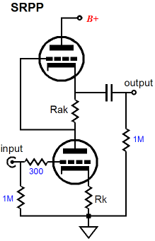
A few weeks ago, I dug out an old SRPP-based line-stage amplifier to give it a listen, as it held a pair of very expensive output coupling capacitors. In other words, I wanted to hear the coupling capacitors, not so much the SRPP circuit. The chassis only held, however, a single pair of output RCA jacks; but I need two pairs, as my powered subwoofers require their own pair of outputs. I decided to listen without the subwoofers. The sound was pleasing but a bit thin sounding to my subwoofer-accustomed ears; so, I attached two RCA splitter connectors and hooked up the subwoofer interconnects. I pressed the play button. My ears encountered two interesting results: no subwoofer output, as I forgot to turn them on; second, the sound slightly but perceptibly worsened. I unplugged the subwoofer interconnects; the sound was restored to its previous glory. What was going on? I have a good guess. The subwoofer interconnects are 3-meters long, which means a good amount of added capacitance attached to the SRPP's output. Now, the SRPP does not present a low output impedance and capacitive loads are not linear in the way a resistor is, being frequency dependent in terms of impedance. For example, an SRPP based on the 12AU7 exhibits a high-frequency bandwidth beyond 5MHz when loaded with only a 100k resistive load; but when loaded by the addition of 500pF of capacitance, the bandwidth falls to 72kHz. In addition, the subwoofer's internal power amplifier's input stage presents a further load on the line-stage amplifier. (Worse, the solid-state input stage may behave non-linearly when turned off, as the input transistors might encounter sufficient input signal to forward conduct, making for a truly non-linear load.) Of course, a robust enough of a line-stage amplifier can probably overpower these awkward loads. Sadly, an SRPP is not all that robust.
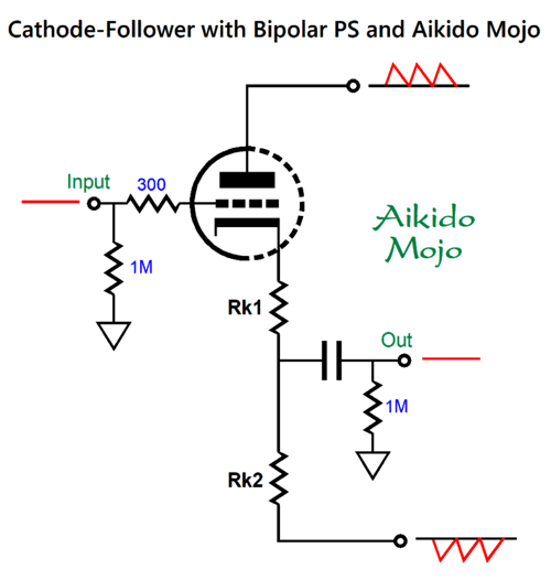
Okay, back to my desire to build a super-simple-but-still-effective audio circuit—since my DAC puts out sufficient voltage to drive my power amplifiers to full output, no signal gain was needed. My first thoughts were along the lines of a single triode configured as a cathode follower situated within a high-voltage-bipolar power supply, which would eliminate the need for an input coupling capacitor. Which single triode?
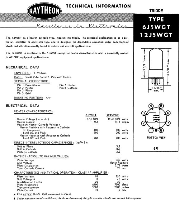
I own a few octal 6J5WGT single-triode tubes (one-half of a 6SN7). I love the idea of these old gems being on display, but I worried that the cathode follower might run into the same problem that the SRPP had encountered. Then it hit me: why not use two 6SN7s instead of two 6J5WGTs? Why? The twin triode tubes would allow the subwoofers to get their own discrete outputs? This is what I chose to do. In addition, to each channel sporting dual separate outputs, if we give the cathode follower two cathode resistors along with the bipolar power supply, we can achieve an Aikido mojo PSRR null—as long as the resistor values are carefully selected.
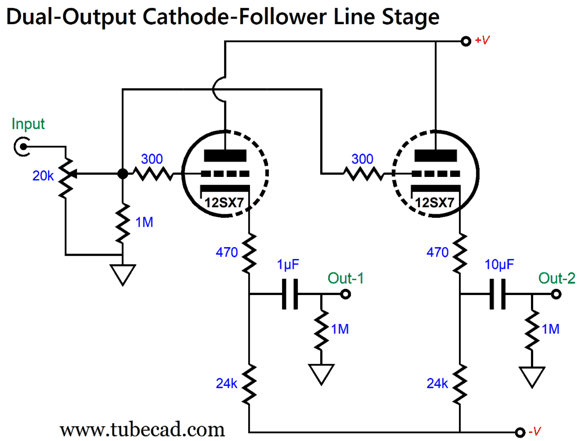
The idea here is that the triode and cathode resistor Rk1 present a combined impedance equal to resistor Rk2, which effectively creates a two-resistor 50% voltage divider. Working on the assumption that each power-supply rail in the bipolar power supply presents the same amplitude of ripple, but out of phase to each other, the 50% voltage division results in zero ripple at the output, as 1 + -1 equals 0. The formula is simple enough: Rk1 = (Rk2 – rp)/(mu + 1) Where, rp is the triode's plate resistance; mu, its amplification factor. With a 6SN7 and Rk2 equal to 24k, Rk1 should be about 820 ohms. I didn't use 820-ohm resistors, as I discovered that I still owned four 470-ohm expensive Japanese carbon-film resistors, so I used them instead. (The RC filters and huge-valued power-supply capacitors used already reduced the ripple to a tiny amount. I plan to buy the expensive 820-ohm resistors soon.) Here is the overview of my unity-gain line-stage amplifier.
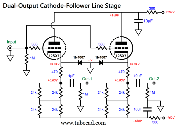
The 12SX7 is a fancy version of the 6SN7. The 12SX7 was designed to overcome the problems that were encountered when 6SN7s (and 12SN7s) were used in the low-voltage circuits that airplanes used. After some research, they discovered that within the 6SN7 many electrons, rather than being absorbed, simply bounced off low-voltage plates. The workaround was to create a special version of the 12SN7, the 12SX7, whose specially treated plates readily absorbed all the electrons emitted by the cathode. At high voltages, the triodes behave exactly the same as their predecessors (but to my ears, sound better). Unlike the 6SN7, the 12SN7 and 12SX7 heater elements run off 12.6V, but at half the current of the 6SN7. The actual circuit I used was a tad more complicated.
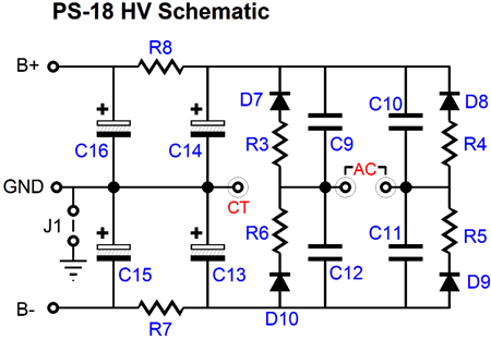
The four 24k resistors in series-parallel equal a 24k load. The 1N4007 diodes protect the 12SX7 triodes at turn-on, when the grids would otherwise be 162 volts more positive than the cold cathodes; with the diodes in place, the maximum positive voltage differential is about +0.7 volts. Once the triodes are hot and conducting, the diodes are no longer forward biased and fall out of the circuit. The 10µF polypropylene capacitors and 300-ohm resistors form RC filters. (The PS-18 high-voltage bipolar power supply also contains two RC filters, R7 & R8 along with C15 & C16.)
The PS-18 high-voltage bipolar power supply also contains a regulated low-voltage heater power supply, which I set up to put out 12Vdc.
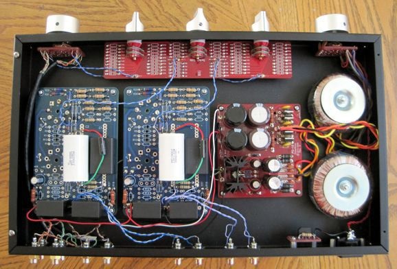
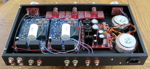
I used two toroid power transformers, one for the high-voltage bipolar power supply and one for the heater power supply, along with my Select AC switch that allows for staggered turn-on of the transformers, with the heater power supply powering up first, then the high-voltage bipolar power supply.
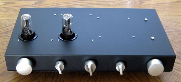
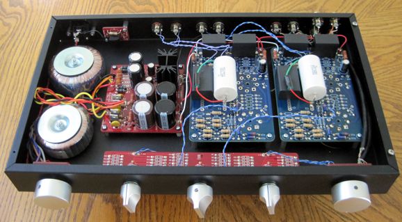
I used one of my input-selector switches and my ladder attenuator, the Attn-Ladder, which allows 144 possible steps of attenuation with the three 12-position rotary switches. The center switch controls both channels and offers coarse 12dB steps, while the flanking switches are specific to their channel and offer fine 1dB steps. In other words, the attenuator also functions as a balance control. Unlike a series attenuator, this ladder design never places more than four resistors in the signal path.
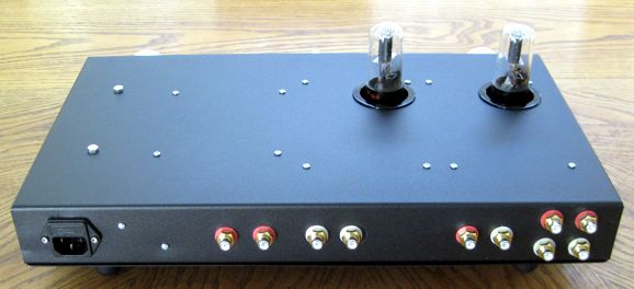
The RCA jacks are NOS (not counterfeit) Cardas jacks from the 1990s. At the left, we see the three sets of stereo inputs; at the right, the two sets of output jacks. (The horizontally positioned input jacks were originally going to be output jacks, as the third input was going to be a 3.5mm miniature jack on the front panel, so I could plug my Sony personal player in there. I changed my mind, as that front-panel input jack ruined the symmetry, so I added a second set of output jacks.)
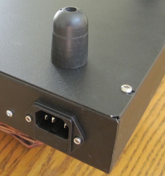
Near the AC power inlet connector, we see one of my House-Ground PCBs. I have yet to perforate the bottom panel. My workaround was to use tall rubber feet, so plenty of space exists under the chassis. The air within the enclosure will circulate due to convection air currents; so as long as the enclosure remains cool, the circulating air inside will use the enclosure as its heatsink.
One missing feature is two toggles switches on the rear panel that would allow bridging the two outputs together for the occasions when no subwoofer is used.
Okay, how does it sound? First of all, never ask a mother if her baby is beautiful. Second, never forget that no one is easier to fool than you are, especially when you have spent a lot of money, mental energy, physical effort, and time on a project. Having said that, I thought it sounded great. In fact, I thought the bass clarity improved. Still, since I don't trust myself, I took the unity-gain line-stage amplifier to my friend's place. He approved of the sound. Later this week, I will bring it to another friend's house.
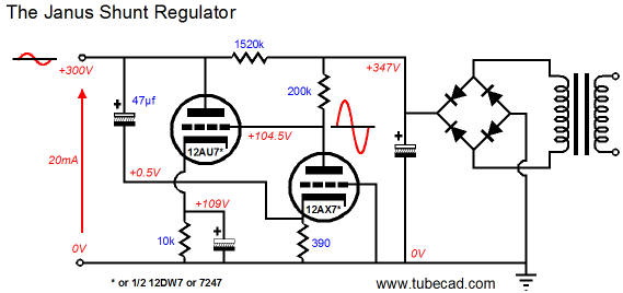
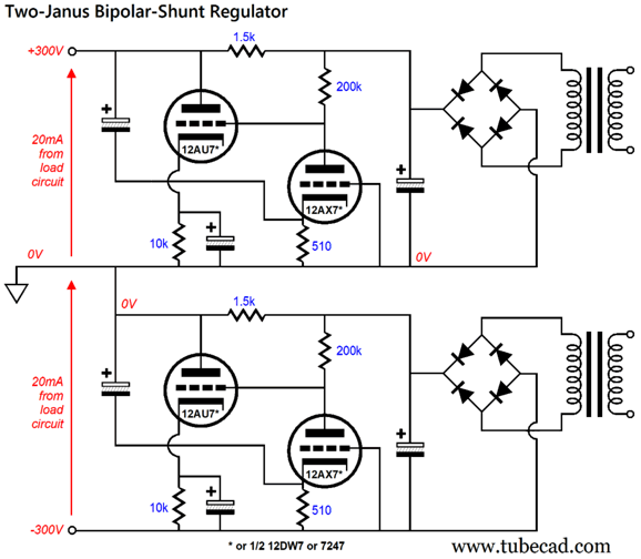
Janus Shunt Regulator for Bipolar Power Supplies
Sorry for the right-to-left presentation, where the output appears at the left, not the usual right, but this is long-held habit of mine when drawing power-supply circuits. (I made this schematic back in 2007.) The 12AX7 triode is in charge in this circuit. The 47µF capacitor relays any perturbations on the output voltage to the 12AX7's cathode, where this "signal" is then amplified, in phase, at the 12AX7's plate. The 12AU7-based cathode follower then delivers a powerful anti-phase current conduction that counters the perturbation. So far, this is standard shunt-regulator functioning.
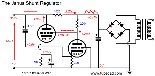
Now, we look at the raw power-supply noise. The 12AX7 triode halves the ripple at its plate, which it then relays to the 12AU7 grid. The 12AU7 once again produces anti-phase current conduction that counters the ripple at its plate. This is feed-forward shunt regulation. If series-shunt resistor value is carefully selected, an amazingly deep power-supply noise null obtains. The resistor's value must equal the inverse of the active shunting device's transconductance. Since the 12AX7 halves the power-supply noise, the 12AU7's effectively transconductance is also halved in this circuit in regards to the ripple. What the Janus regulator does is to combine both the standard and the feed-forward shunt techniques into one circuit. Moreover, we can make a bipolar power supply by simply bridging two Janus power supplies together.
Note that two separate high-voltage secondaries are used and that a single center-tapped secondary will not work. Using two positive regulators to make a regulated bipolar power supply often proves the best way to go, as the duplicated parts are a feature, not a liability in terms of stocking parts. In addition, often we cannot source equally good negative-regulator parts as used in the positive regulator. This is why I created my Dual/Bipolar LV-Reg, as negative three-pin solid-state regulators are not as good as their positive brothers.
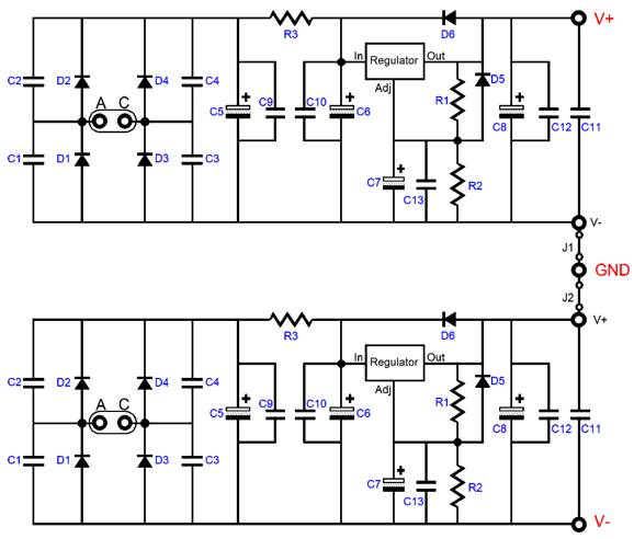
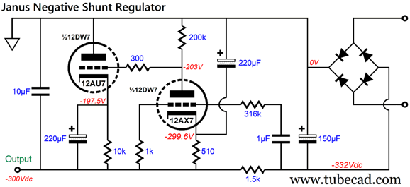
Note the RC filter made by resistor R3 and capacitors C6 & C10. This pre-filter greatly improves the regulator performance, as it pre-scrubs away the high-frequency rectifier hash. The less work the solid-state regulators have to do the better. (Most solid-state IC regulators present their best PSRR figure at around 100Hz, which is the ripple frequency with a 50Hz wall voltage.) Well, this got me thinking: what if I designed a negative version of my Janus that placed the shunt resistor in series with the raw negative power-supply rail? Would it be possible, as no negative-triode exists in the same way that negative PNP transistors and P-MOSFETs exist? Why would we desire such a regulator? Answer: so we can use a conventional high-voltage center-tapped secondary. Here is what I came up with:
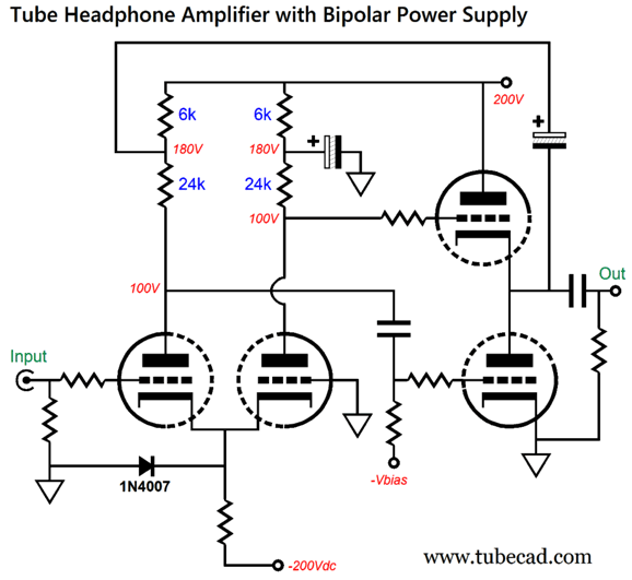
This negative Janus also looks forward and backwards. The magic trick is found in the 1k and 316k resistors, which allow 99.7% of the output to enter the 12AX7's grid, while 1/317th of the raw power-supply noise also enters, which is enough to create a power-supply noise null. It's time to consider the two types of bipolar power supply loads: symmetrical or balanced and unbalanced. The following tube-based headphone amplifier presents a near constant current draw on the negative power-supply rail, but a highly variable draw on the positive power-supply rail.
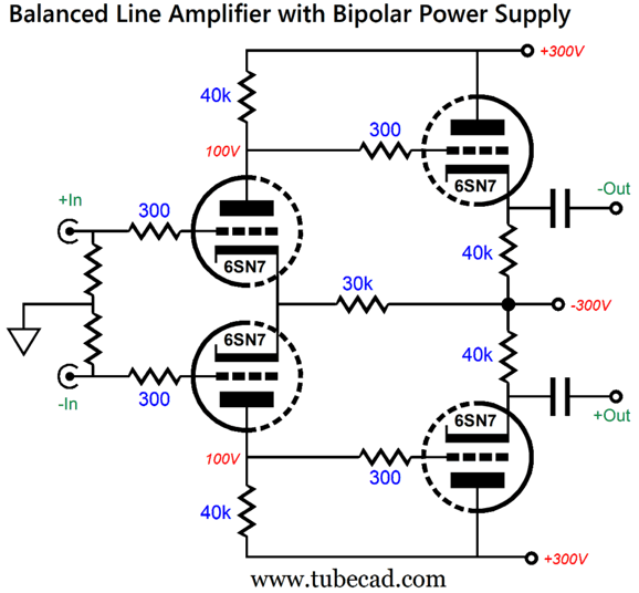
The totem-pole output stage must deliver small voltage swings, but at high current; in contrast, the long-tail resistor on the input differential stage draws far less current and sees a near constant current flow. This is a very asymmetric (unbalanced) load. In contrast, the following differential line-stage amplifier presents a balanced loading of both power-supply rails.
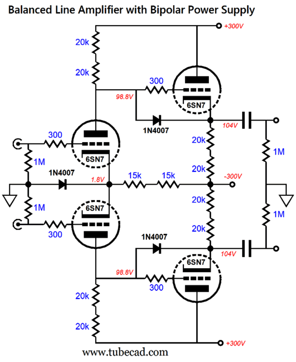
Both of the bipolar power supply rails experience the same current draw, at idle and with input signal. Since I fear someone actually building this circuit, here is the fleshed-out version.
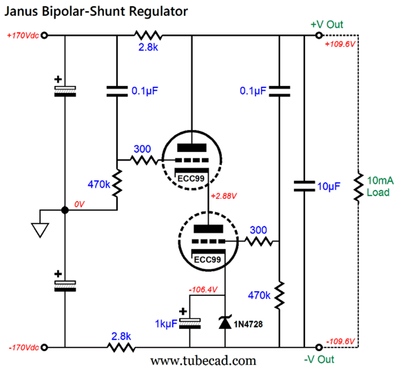
The added diodes make the circuit safe. The series resistors reduce distortion, while providing great heat dissipation. A single heater power supply can be used if it referenced to around +50Vdc, as that would split the voltage differential between the heaters near ground potential and those in the cathode follower output stage. With a balanced load like this one, we can use a far simpler bipolar Janus regulator.
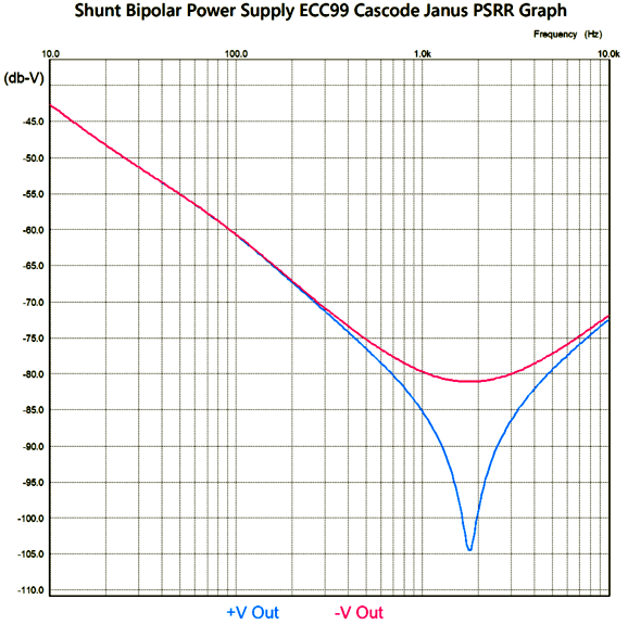
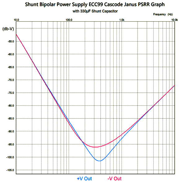
I created this version almost 20 years ago but failed (as far as I can remember) to show it here. The top ECC99 triode sees at its grid all of the raw positive power-supply noise, which forces an anti-phase current conduction through both triodes, creating a power-supply noise null due to the 3k series resistors. The bottom triode sees the signal after the series resistor at its grid through the 0.1 µF coupling capacitor. In other words, the top triode deals with raw power-supply noise and the bottom triode deals with the audio-signal-induced perturbations on the bipolar rails. The assumption here is that the bipolar power supply will present equal but out-of-phase ripple on its two voltage rails. If the secondary holds a miss-tapped center-tap, this will not prove to be the case; the same holds true with an unbalanced load. How well does this bipolar power supply work?
If we replace the 10µF capacitor with one with more capacitance, say 330µF, the null extends further down in frequency.
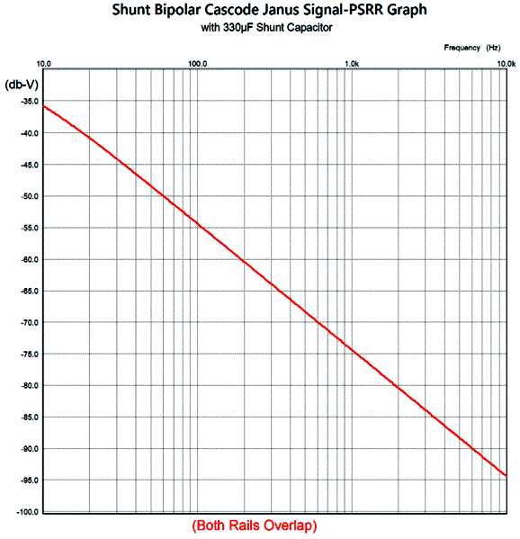
We gain a further -15dB reduction at 100Hz. Note how the two plotlines come closer to converging. This implies that some greater capacitor value would force an exact overlap on the two. What about the power-supply noise that results from an unbalanced load circuit creating a deviation from constant-current draw? (A truly balanced audio circuit would draw a constant current.) Measuring this aspect of the bipolar Janus cascode took some head scratching. I believe I found the answer. We assume an external audio circuit that draws a nominal 10mA at idle, but under signal conditions, its current draw varies by 0.79mA, which would force +/-1Vpk of rail-voltage swing without the shunting capacitor and the bottom triode connecting to the +Voltage rail through a coupling capacitor. Here is the resulting SPICE-generated graph.
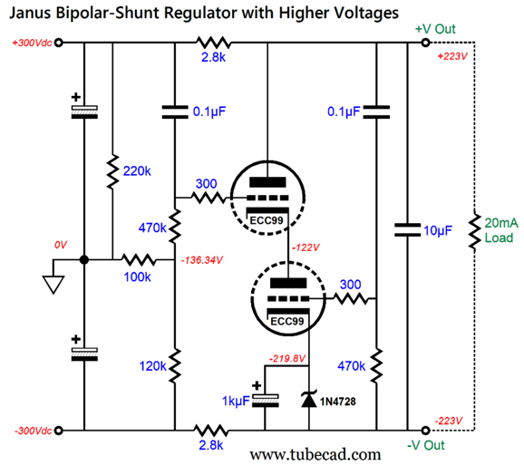
The attenuation is not as great as it was when the shunt regulator was looking backwards at the power-supply noise created at the rectifiers, as the ECC99's transconductance was reduced by the two 2.8k series resistors. By the way, 2.8k is a standard 1% resistor value, but not a 5% value. Sadly, most 3W and 5W power resistors come in the 5% tolerance. The workaround is to place two 5.6k power resistors in parallel. The cascode shunting tube will need its own floating heater power supply, one referenced to around -50Vdc. What if higher voltages are needed? Well, we might run into too great a voltage between the two cathodes.
In this design example, we see much higher voltages and twice the load-current draw. The 100k and 120k resistors form a two-resistor voltage divider that delivers a -136.3Vdc reference voltage for the top triode. The top triode sees a cathode-to-plate voltage drop of 345V, while the bottom triode only sees 102V of voltage drop. A heater power supply referenced to around -170Vdc should be used.
Music Recommendation: Nobody's Fool
I soon discovered that she had released a new album this year, Nobody's Fool. The music genre is a throwback to the last century's rhythm and blues style. A vocal chameleon, James delivers a compelling performance. Her efforts were helped by the 24-bit, 192kHz recording offered by Amazon Music (24-bit, 88.2kHz at Qobuz). //JRB
Did you enjoy my post? Do you want to see me make it to post 1,000? If so, think about supporting me at Patreon.
User Guides for GlassWare Software
For those of you who still have old computers running Windows XP (32-bit) or any other Windows 32-bit OS, I have setup the download availability of my old old standards: Tube CAD, SE Amp CAD, and Audio Gadgets. The downloads are at the GlassWare-Yahoo store and the price is only $9.95 for each program. http://glass-ware.stores.yahoo.net/adsoffromgla.html So many have asked that I had to do it. WARNING: THESE THREE PROGRAMS WILL NOT RUN UNDER VISTA 64-Bit or WINDOWS 7, 8, and 10 if the OS is not 32-bit or if it is a 64-bit OS. I do plan on remaking all of these programs into 64-bit versions, but it will be a huge ordeal, as programming requires vast chunks of noise-free time, something very rare with children running about. Ideally, I would love to come out with versions that run on iPads and Android-OS tablets.
| I know that some readers wish to avoid Patreon, so here is a PayPal button instead. Thanks.
John Broskie
John Gives
Special Thanks to the Special 85 To all my patrons, all 85 of them, thank you all again. I want to especially thank
All of your support makes a big difference. I would love to arrive at the point where creating my posts was my top priority of the day, not something that I have to steal time from other obligations to do. The more support I get, the higher up these posts move up in deserving attention.
If you have been reading my posts, you know that my lifetime goal is reaching post number one thousand. I have 411 more to go. My second goal was to gather 1,000 patrons. Well, that no longer seems possible to me, so I will shoot for a mighty 100 instead. Thus, I have just 15 patrons to go. Help me get there. Thanks.
Only $12.95 TCJ My-Stock DB
Version 2 Improvements *User definable Download for www.glass-ware.com
|
|||


| www.tubecad.com Copyright © 1999-2023 GlassWare All Rights Reserved |