| John Broskie's Guide to Tube Circuit Analysis & Design |
A letter from Poland 17 June 2003
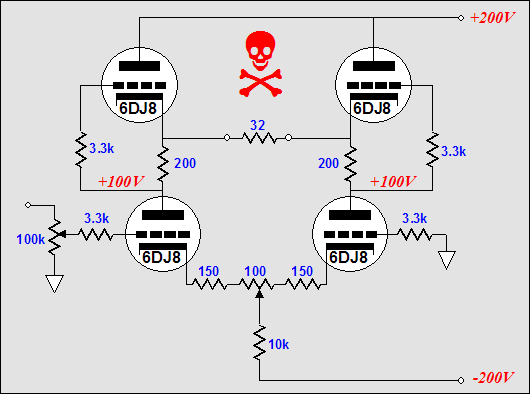
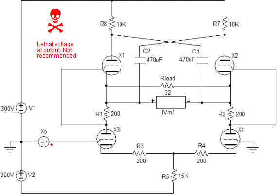
Caution: Lethal voltage at output. Not recommended!
The goal of “no capacitors, no feedback” is laudable—within reason. In designing my own equipment, I always strive to use the fewest capacitors and the shortest feedback loops possible or, preferably, no feedback—within reason. And reason tells me that if I use a plate resistor then I have added a feedback mechanism to my circuit. The same holds true if I use an unbypassed cathode resistor or even if I just use a triode, as each constitutes a feedback loop of sorts. The tip-off is “does distortion go down?” If it does, then feedback is probably being used in some form. (On the other hand, pre-distorting the signal in an inverse complementary fashion can lower distortion without creating a new feedback mechanism. See "Complementry Inverse Distortion Cancellation" for details.) Sometimes, however, it is difficult to see a feedback loop. In the following circuit, is there a global feedback loop or not?
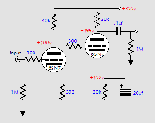
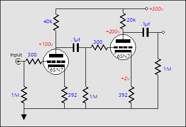
A similar situation is found when trying to go capacitor-less. Just because no coupling capacitor can be seen does not necessarily mean that the signal does not flow through capacitors. In the illustration below, on the left, we see my favorite implementation of the a popular input stage and phase splitter, which has been, in this instance, optimized to lower power supply noise in the following push-pull gain stages. On the other hand, the circuit on the right seemingly does away with the first circuit’s internal coupling capacitor. Or did it?
First of all, the circuit on the left is not as capacitor-coupled as you might imagine, as the 1M resistor in parallel with the coupling capacitor allows a good bit of DC signal to flow across the capacitor (66%, in fact). Second, the circuit on the right is not as coupling-capacitor free as you might imagine, as the 20µF capacitor puts in place the same primary time constant as the .1µF capacitor does, but in an inverse way. Where the first circuit offered more gain at high frequencies than at DC, the second circuit offers more gain at DC and low frequencies than at higher frequencies. Which is better? Which do you need? And for what application? One thing is for certain: electrolytic capacitors sound worse than just about any other type of capacitor. Well, what if we do away with the second circuit’s 20µF capacitor altogether, wouldn’t that be the best way to eliminate unwanted coupling capacitors? The coupling capacitor would be gone, but the power supply noise would be back. Actually, the best solution might be to eliminate the first circuit’s 0.1µF capacitor! We lose 33% of the first stages gain, but we avoid capacitor problems, while retaining our improved PSRR figure.
Once again, we are presented with two circuits, i.e. two choices. This first circuit is popular with the single-ended crowd, as it offers a good deal of gain and seemingly eliminates the need for a coupling capacitor (notice that the cathode-bypass capacitor must be used or the second ground-cathode amplifier will not provide any gain). The second circuit is more conventional and it too offers a good deal of gain.
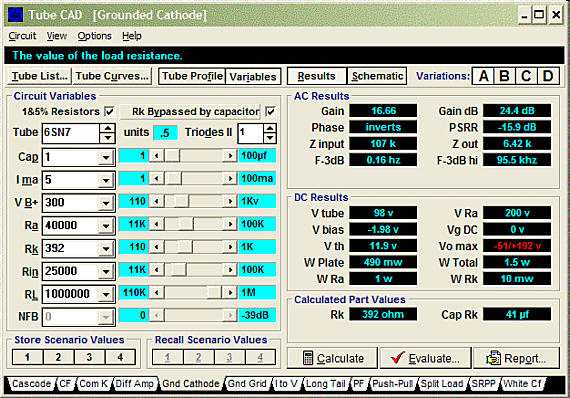
If the screen capture above looks unfamiliar, shame on you and doubly shame on me. (The original idea behind this website was that all the articles would illustrate how to use Tube CAD when designing tube circuits. In this respect, this webzine was meant to mimic the excellent Math Soft Math CAD Journal. But I felt that promoting my software wasn’t as important as promoting a better understanding of tube circuitry. Math Soft was lucky, as math wasn’t in trouble; I wasn’t so lucky, as I felt that tube circuitry was. )
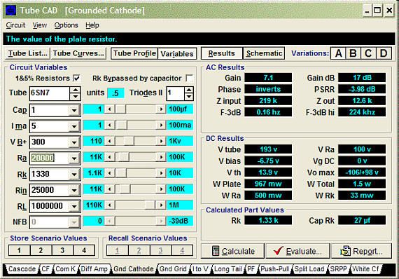
The next screen capture shows the second circuit’s second stage’s configuration. Note the larger symmetrical voltage swing, but a lower gain and a higher output impedance.
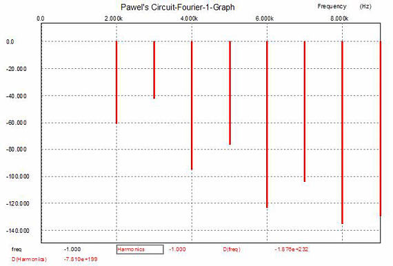
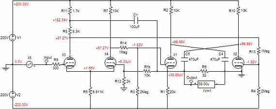
Which is better? “Better for what?” is the question. Which is more important: gain, output impedance, output voltage swing, or PSRR? And then, which is worse: having the signal flow through an electrolytic capacitor or a film/oil capacitor? Fortunately, testing these two circuits is easy enough: simply build the second circuit and tack solder a coupling capacitor, a 1Meg resistor and a 20µF electrolytic capacitor to ground only. Next test, listen, evaluate. Then tack solder the electrolytic capacitor’s other end to the second triode’s cathode and unsolder the 1Meg resistor’s connection to the 0.1µF capacitor and short this capacitor out with a piece of wire. (Of course, the amplifier has been unplugged from the wall and the power supply capacitors have been discharged first... audio constructors are already going extinct without any extra help.) Once again, test, listen, evaluate. (My guess is that if the output tube [or tubes] is an EL34 or 6550, then the first circuit just might be the winner, but if the output tube is a 300B or 211, then the second circuit would clearly be the winner, as these tubes require a much larger grid voltage swing.) So you see, Pawel, going capacitor-less and going without feedback isn’t as easy or as obvious as we might imagine. Furthermore, I haven’t even touched on the topic of safety. Do you really want to risk $600 Grado headphones on a capacitor-free output stage? Hook up a voltmeter to the outputs and blow on side of one tube and see if the reading doesn’t change by a few volts. Speaking of safety, I would never put my son’s father’s ears between two thinly isolated wires that connected to a 100V power supply! (My ears sweat after half an hours worth of headphone listening.) A final quibble is on the topic of potentiometers, like the one used to set the DC balance in your design. Put plainly, most potentiometers are crap. They lose scraper contact, they burn out when overburdened, and they can sound much worse than an electrolytic capacitor. Yet audio neophytes love them for some odd reason (maybe they can understand their inner workings, unlike a pentode or MOSFET). One good rule to follow is never to pass a DC current through the potentiometer’s scraper, unless the potentiometer was specifically designed for the task. Bear in mind that a 1W potentiometer is only capable of withstanding 1 watt of dissipation across its outer leads. Thus the practice of using a potentiometer as a variable resistor is unwise, unless the currents and/or voltages are truly trivial. But enough quibbling, let’s look into your circuit. First of all, just about everyone who dabbles with tube electronics comes up with this topology at some time. It seems to offer everything we want: DC coupling throughout, gain, and a low output impedance. Well, it is DC coupled. When burdened with a 32-ohm load this circuit’s high output impedance (3k from cathode to cathode) realizes very little gain, 0.156 to be exact. In other words, it takes 2 volts of input signal to equal 0.312 volts of output signal. The distortion is fairly good at about 1%, with odd order harmonics leading over even order, which is typical of a push-pull amplifier. 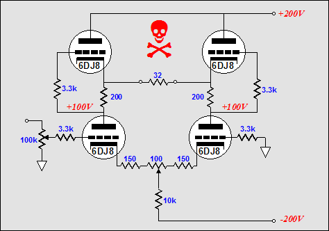 Pawel’s circuit: a DC coupled headphone amplifier
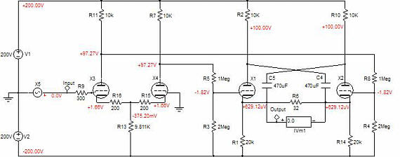
Well, how do improve the performance in terms of gain and output impedance? Different tubes or more tubes? Or how about an output transformer? Any of these would help, but each has its own problem area. For example, using a higher mu triode (12AX7 or a 5751, say) for the bottom differential amplifier would increase the gain, but it would also severely lower the idle current into the top triodes (a workaround would be to add resistors from the top cathode to ground). Doubling the total number of triodes would halve the output impedance, but only halve an already extremely high output impedance (3k relative to 32 ohms is extremely high by anyone’s standards). Well then, how about an output transformer? Output transformers are electrical levers that magnify the load impedance, while reducing the output voltage swing and increasing output current swing. So while we would see a greatly reduced output impedance (3k divided by the wing ratio squared), the voltage gain would also fall by the winding ratio of the transformer. (Actually, in this case, where the load impedance is so grossly mismatched to the amplifier, the gain reduction would not be so great, as the amplifier could realize more gain before it was reduced by the transformer.) Additionally, output transformers bring the issue of airgaps; if a non-airgapped output transformer sees a net DC magnetizing current, it saturates, which in this circuit, it could easily, as absolute DC balance would be difficult to guarantee. So a coupling capacitor for the output transformer’s primary might be the better way to go, although in violation of Pawel’s first goal. If we pull back a few hundred feet and look at the circuit, we that the 32-ohm load is terminates into some very spongy components: the triode’s rp and a 10k resistor. If we could shorten the current path with low impedance devices, the situation would improve greatly. In the schematic below, we see a circlotron transformation of Pawel’s circuit. (Once again the poor naming convention or lack of a naming convention arises. The actual Circlotron circuit used more tricks than two power supplies. A better name for this sort of topology might be “Figure Eight,” as the current circle has been twisted or folded on itself, like a rubber band made into a figure eight. Or, perhaps, “Horizontal” would be a better name, as it would find a compliment in “Vertical,” what we now call “Totem Pole.” Here is a set of questions for the more accomplished tube practitioners: given a horizontal and a vertical amplifier with the same output tubes and same power supply wallop, i.e. the horizontal amplifier holds two 100V power supplies, the vertical, one 200V bipolar power supply, how will they differ in gain, output impedance, harmonic distortion, maximum voltage swing, and maximum current swing?) Note the increased power supply voltages and the addition of two resistors (R8, R7) and two capacitors (C1, C2). These added parts allow the top triode’s cathodes and plates to be tightly coupled in AC terms, while preserving their DC independence. To see how this works, imagine throwing a 2-volt battery across the outputs. One cathode would go up 1 volt, while the other would go down 1 volt; one plate would go up 1 volt, while the other would go down 1 volt. Since the added capacitors do not look like coupling capacitors, looking more like power supply capacitors, are they in the signal path? As so much of audio is psychological, they probably will fly below most audiophiles’ radar, while in fact they are 100% in the signal path. (I once knew this tubeaholic who refused to use Radio Shack 6FQ7s, even though they where relabeled Amperex tubes, because he did not want his system’s sound contaminated by a “Realistic” product.) With the added parts, the output impedance falls to 1k (three times better) and the gain climbs to 0.263 (twice as good) and the distortion also takes a dive down to 0.1% (one tenth it previous value). Not bad, but not great enough, given the 32-ohm load; and the issue of safety remains. The high output impedance is a only nuisance, but the safety hazard is the pressing danger. How can this amplifier be made safe? If the added capacitors were replaced with four capacitors, one capacitor replaced with two in series, then we could attach the load at the capacitor’s midpoints, which could be referenced to ground via two resistors. Thus the circuit’s functionality would remain, while our ears’ safety is ensured. Following is the schematic of the amplifier improved and made safe. 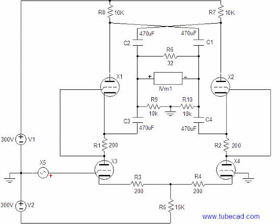 AC coupled headphone amplifier with added “Horizontal” making capacitors Yes, we have violated Pawel’s first rule, but at least we will not be leaving behind any widows (or widowers, I know that this webzine has at least three female readers). Because the circuit is now completely capacitor coupled, we can eliminate resistors, R3 and R4, which represented the two 150-ohm resistors and 100-ohm potentiometer in Pawel’s original circuit. Their removal will increase the gain and lower the output impedance somewhat. Still, four coupling capacitors is a bit much (each glibly draw capacitor actually represents a cluster of capacitors: a 470µF electrolytic in parallel with 10µF and 0.22µF film capacitors). The circuit below drops the SRPP affectation from the circuit by separating the differential amplifier from the output stage. DC coupling is accomplished by using two voltage dividers, which lose 33% of the differential stage’s signal, but they allow a 100-volt DC shift in the signal! To what effect? Where we were gain starved, we are only gain hungry, as the gain climbed from 0.263 to 1.32. The output impedance has fallen to 40 ohms, an eminently useable value. But the distortion is back to 1%. We are getting closer, but we are not there yet.
To lower the distortion further means that we are going to have to resort to feedback, as the input stage is much cleaner than the output stage. Thus wrapping a loop back to the input stage means that it can iron out the output stage’s non-linearity. Pawel must be pulling out his hair right now, but we can make a swap: we will use feedback, but will not use the coupling capacitors. The circuit below will confuse many. The circuit is no longer balanced at the output, which is actually a plus, as most headphones come with a standard plug, not an XLR connection. Wait a minute, don’t circlotron type amplifiers have to have a balanced, floating output? No, they don’t. Remember ground is not a physical component that you can buy at Radio Shack, it is a point of reference, nothing more. Yet many speak of “ground” as if it were an electrical black-hole or magical entity. The tubes, resistor, and capacitors are blind to “ground.” All they know is that so much current flows through them or so much voltage is present across their leads. If you name the positive terminal of a 9-volt battery “ground,” then you have a 9-volt negative voltage source; if you name the negative terminal “ground,” a 9-volt positive voltage source. (I have been told that grounds cannot be become polluted or dirty, as a ground is perfect —you know, metaphysically, which is, in fact, true, as long the infinitely small point of chassis or wire that has been christened “ground,” is the only point under consideration, not any of the adjoining atoms of metal, let alone the end of a long, snaking coil of 22-gauge wire.)
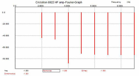
Consider this: grounding the output stage’s second triode does not stop it from working. As its grid sees a varying voltage relative to its cathode, it conducts a varying amount of current, which must flow through resistors, R10, R6, R1, Rfb, R12, R2, and the triode, X1, as capacitor C5 AC couples its plate directly and indirectly to those other circuit elements. For example, when the grounded triode sees a positive grid voltage, it conducts more, pulling its plate down in voltage, which in turn pulls the amplifier’s output down in voltage; at the same time the other triode sees a negative grid voltage, so it conducts less, pushing its cathode down in voltage as well. Thus the grounded triode’s cathode is locked, but its plate is free to move; the floating triode’s plate is locked, but its cathode is free to move. Both triodes see the same cathode-to-plate voltage at idle and each sees the output signal in anti-phase: if one triode sees an extra 2 volts, the other will see 2 volts less. But how can this output stage cannot be balanced, as the grounded triode works as a grounded-cathode amplifier, while the other works as a cathode follower? True enough, if it were not for the added capacitor, C1, which relays any perturbation at the output back to the grounded triode’s grid, which converts the grounded-cathode amplifier into a cathode follower (plate follower is closer to the mark). Thus balance is preserved. Doesn’t the difference in plate resistors, R8 and R7 undermine balance? No, in fact, this discrepancy actually promotes balance. The long-tail phase splitter is not perfect in that it does not offer a perfectly balanced output. Well, if a constant current source is used in place of a cathode resistor, then perfect balance would be ensured, right? Wrong. Even a perfect constant current source is not enough, as balance will be off by at least 1/mu. Reducing the first plate resistor’s value by the required amount reduces the gain at its plate to the same level as the opposing plate. We were lucky enough to hitch a free ride on this circuit’s failing. (I like to think of this as Aikido applied to electronic design. What do you think of the title Audio Aikido for a book? Kind of snappy, in a eastern-looking, trendy, California way; but would it sell?) 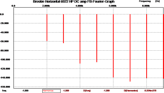 Fourier analysis of the headphone amplifier above (0.32 volts into 32 ohms) in B2 Spice A/D The distortion results are interesting. Note how the 2nd and 3rd harmonics are almost equal and how the same holds true for the 4th and 5th harmonics. Compare this graph with the last graph to see the vast improvement. (Some may like 2nd and 3rd harmonic distortion, but no one likes 6th, 7th, 8th, and 9th harmonics, with which this amplifier nicely dispenses.) The output impedance is a low 24 ohms, which much better suits driving 32 ohm headphones. So, Pawel, how unhappy are you with the path I have taken? I know which headphone amplifier I would prefer to listen to (“to which I would prefer to listen” sounds too weird to my ears). Before anyone writes to ask if 300-ohm headphones can be driven, the answer is yes. Before anyone writes to ask if 5687s, 6BX7s, or EL84s can be used, the answer is yes, if resistor R5’s value is adjusted to set the output to close to zero volts. And before anyone writes to ask if a power amplifier could be made from this circuit, the answer is no. This amplifier was meant to work in a true, not an advertising, class-A mode, not that it can’t put huge class-AB peaks for short durations, something Pawel’s original circuit cannot do. But a real power amplifier could be made if resistors R1, R2, and R10 were eliminated and capacitors C1 and C2 were replaced by independent power supplies. As I look at the schematic, I am still worried about safety; this time I am concerned about the output tubes, more than the headphones or the listener. What happens when the amplifier is first turned on and the output tubes are still cold? The cathodes will be at negative 200 volts, while the grids will be at 0 volts; not a good idea. Or what happens if someone pulls an output tube out of its socket while the amplifier is use? For safety’s sake, I would add several solid-state rectifiers in series to the output and ground, reverse biased, so that they would only conduct when the output falls below 3 volts, say. 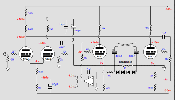 TCJ horizontal headphone amplifier, capacitor coupled with DC servo loop Here is one last variation on a theme (I can easily keep writing and drawing until this blog entry becomes a thick book that is never published). Unfortunately, there isn’t time to go into Pawel’s solid-state circuit; maybe next time. //JRB
|
SE Amp CAD™ is the Windows program that helps you design, understand and modify single-ended amplifier output stages. With SE Amp CAD, you can point and click to a new output stage configuration in minutes. SE Amp CAD is a virtual workbench for single-ended output stage design. True Curves™ is the name of the new mathematical model used in SE Amp CAD. True Curves knows how a 300B or an 845 really bends: how the plate current varies with changes in grid to cathode voltage versus changes in plate voltages. Windows 95/98/Me/NT/2000/XP |
|||


| www.tubecad.com Copyright © 1999-2004 GlassWare All Rights Reserved |