19 November 2004
Two readers have written asking what would happen if vacuum-tube circuits were translated into solid-state circuits, would they sound similar? Good question. The answer depends on the topology and the degree to which the fundamental differences in mode of operation between solid-state devices and triodes work influence the outcome. One quick answer might be that the results would be similar to what pentodes would produce in the same circuit topology.
By the way, lest you don't know, MOSFETs are available in depletion mode: they can conduct current in face of a negative gate-to-source voltage, much like a triode or pentode. In other words, a source resistor can be used to self bias the MOSFET, once again, much like a triode or pentode. These devices are available in high-voltage versions and in low wattages. See the DN2530 PDF for an example.
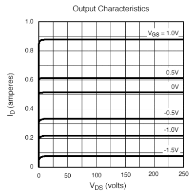
Notice how the MOSFET draws 0.5A at 0 gate-to-source volts. This similarity to tube biasing can go a long way in simplifying a translation from vacuum to silicon. Still, MOSFETs do not hold a drain resistance in the why that a triode holds a plate resistance. Thus, the Aikido amplifier, for example, will not translate without some adjustments.
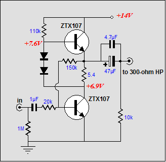
Now, in a past article, I have displayed a MOSFET-based White cathode follower type circuit—but what about the SRPP, can it be translated? Sure, here's how:
The two transistors define a small push-pull amplifier that uses a feedback loop to both lower distortion and output impedance and to maintain DC operating points. The two diodes are 1N914s and they allow a DC offset to rely the drive signal to the top transistor. The input coupling capacitor can be decreased in value to .22µF in most cases, without losing too much bass.
I came up with this circuit when I used to walk a few miles to work and I would listen to my portable CD player, which could not put out enough juice to overcome irksome street noises. I planned on putting this circuit in a small Altoids box with two rechargeable 9-volt batteries (7.2 volts each, in actuality), but I was still obbsessed with the idea of building a portable tube-based headphone amplifier, so the circuit never made it off the bench.
How well does it work? Here is a SPICE simulation:
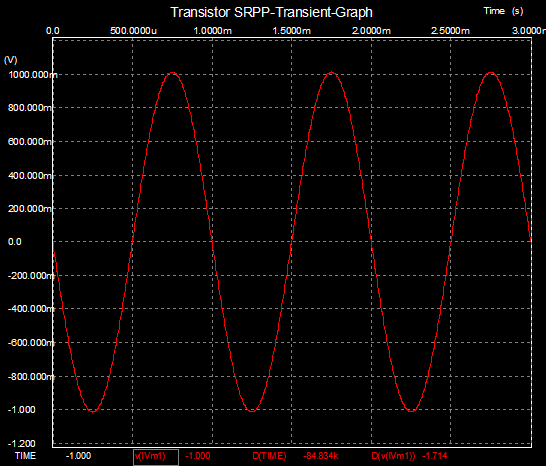
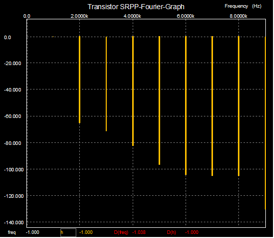
At 0.1% distortion at 1 volt out, this isn't a bad little amplifier. If the center resistor's (the emitter-to-collector resistor) value is carefully chosen, the even harmonics can be further reduced—but why?
17 November 2004
I had to cut the comparison between the Gomes and the Aikido amplifier short last time (for the usual reasons: no time and the blog was running far too long).
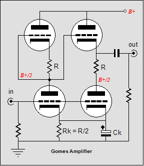
I pointed out that the Gomes amplifier works worst into low-impedance loads and best with an infinite-impedance load. Why? This push pull amplifier does not provide a balanced/symmetrical drive voltage to top and bottom tubes, which the low-impedance load exposed and infinite load impedance hid (by not allowing the amplifier to work in push pull mode). On the other hand, the XPP amplifier worked substantially better into low-impedance loads and probably best into load impedance closer to the triode’s rp. So what are we to conclude, that the Gomes amplifier is a poor design? Yes and, most emphatically, no. Yes, we should not use the Gomes amplifier for driving Grado headphones; but then there are other loads than low-impedance headphones. Wait a minute—isn't the nonsymmetrical drive always going to be a problem when driving any non-infinite load impedance?
Now we arrive at the subtle truth.
Do not assume that all loads are purely resistive, as many—including the headphones—are reactive-resistive mixes. Others are purely reactive, such as electrostatic headphones. And others still are non linear, being nonsymmetrical in relation to voltage. First of all, a resistor does not observe voltage polarity; placing a 1k resistor across a 9-volt battery always draws the same amount of current no matter what the polarity connection is. This does not hold true for all electronic devices. Diodes come immediately to mind, as their function is to behave nonsymmetrically in relation to voltage polarity. When a diode is forward biased, it conducts wildly, i.e. it offers little resistance; when reversed biased, it conducts not at all, i.e. it offers infinite resistance. Sure, but who drives diodes with amplifiers? We do—all the time.
One of the great advantages the triode holds over a transistor is that the triode’s controlling element, its grid, presents such a high input impedance (unlike the transistor’s base, which presents a relatively low input impedance)...usually, that is. The grid forms a diode with the cathode, a diode which is usually operated in a reverse-biased configuration, but not always. If the grid becomes more positive than the cathode, it no longer is reverse biased and it begins to conduct heavily. (In fact, we can disconnect the plate from the circuit and use the grid and cathode to define a diode; or we can use the grid as the plate, and use the plate as the grid.)
Now if we look at the original use to which the Gomes amplifier was put—driving 211’s grids—we can see a real advantage. The 211’s grid is normally so negatively biased relative to the cathode that its resistance is effectively infinity (the grid-bias resistor defines the load resistance). So what happens when a nonsymmetrical load meats a nonsymmetrical amplifier? Magic.
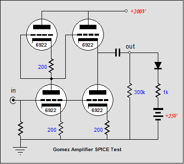
The Gomes amplifier delivers low distortion into the grid when it is negatively biased and high current when it is positively biased. Note that in this application, there is never a need to deliver high current in a negative direction, only positive. (Unless, that is, you decide to use a transformer to couple the Gomes amplifier to the grid and you get the phasing wrong. In this case, this is the wrong circuit at the wrong place at the wrong time.) Below, we see the Gomes amplifier test in SPICE. Note removal of the resist below the output (trust me, it does little good).
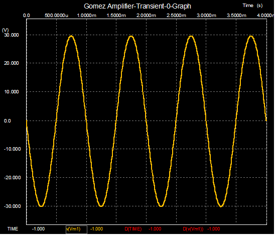
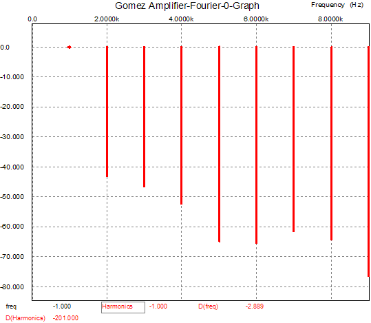
Empresssive results: only 1% distortion into a tough load. In contrast, the Aikido amplifier—using the same tubes and voltages—doesn't work as well with the same nonsymmetrical load, as shown below.
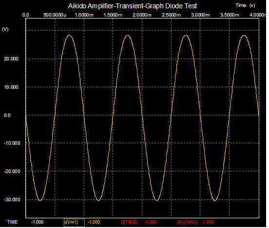
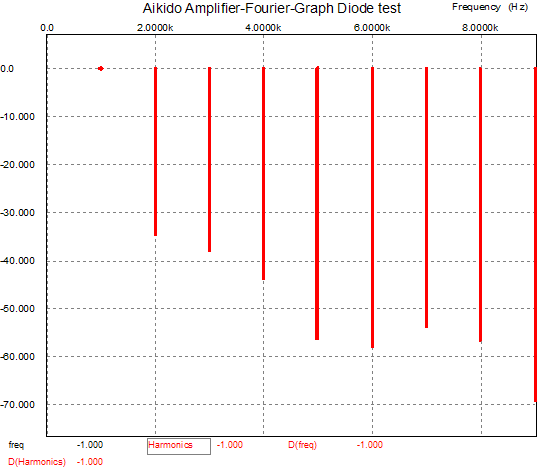
Now it’s time to look for flies in the ointment. Yes, the grid presents a low resistance when negatively biased, but the impedance it presents depends on frequency. The dreaded Miller-effect capacitance comes into play once we move out of pure DC voltages and currents. Fortunately, the audio band is a narrow one that ends somewhere between 20kHz to 60kHz, not megahertz. Still, a wimpy triode or trivial idle current are not a good choice for the Gomes amplifier at high frequencies when driving a triode’s grid and Miller capacitance (pentodes might be a different story). Actually, I think I’ll take back that last set of parentheses; when the grid does go positive, or gets close, it can present a fairly low resistance that will need a fairly buffed driver tube to drive cleanly.
Avoid thinking in terms of "best" in general and think in terms of best in a particular circuit.
Thus, we might think of using a Gomes amplifier as an output-tubes driver; the XPP amplifier, as a low-impedance-load amplifier, for such loads as headphones; the SRPP, as cheap/simple push-pull amplifier for a fixed load impedance; and the Aikido amplifier, as a preamplifier or line stage amplifier.
15 November 2004
Please tell your friends about this blog. I know that many believe this site is abandoned; let them know otherwise. The more readers it garners, the better the excuse I have for writing it. Thanks in advance.
Since last Friday, I have been barely able to catch my breath. I don't really grasp the point of blogging, which has to be short and often. By nature, I am an essayist, not a diarist or a Post-It-note scribbler. (In high-school, my favorite writer was Aldus Huxley, the essayist who pretended to write novels; and today, I still prefer reading an encyclopedia to reading fiction.)
More to the point, the topic of audio Aikido deserves a thick book, not just a few remarks made in passing (the urge to write "en passant" was almost insurmountable). However, most dislike thick books and even as little as asking for ten minutes can be a strain in many readers lives. (I am convinced that there are two types of people: those who believe there are two types of people and those who don't. But, I suppose that we can further subdivide the humanity into those who have too little time and those who have too much. Given a choice, I much prefer belonging to the first group; I could really use a 30-hour day. And how sorry am I for the those in the second group, trapped in boredom.)
The Aikido cathode follower stage is more universal than you might expect. It does not have to be tied to a grounded-cathode amplifier, as any other amplifier stage can be used. I the schematic below, we see a grounded-cathode amplifier cascading into a split-load phase splitter, which in turn cascades into the CF stage.
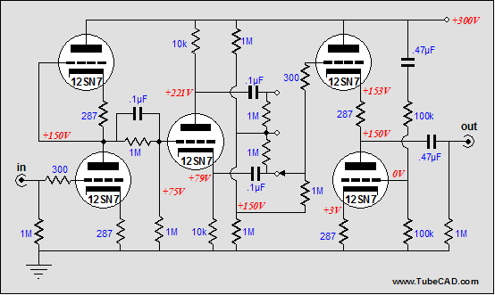
The input stage provides a gain equal to half of the triode's mu and it allows 50% of the power-supply noise leak through to it output. The split-load phase splitter is a much better circuit than it is given credit for being, if you know how to use that is. Most don't. The circuit offers two outputs: one with phase reversal, the other without; two different output impedances and two different PSRR figures. The output at the plate inverts the signal and has a high output impedance roughly equal to the plate resistor's value and it has an almost nonexistent PSRR. In contrast, the cathode output preserves the signal phase and has a low output impedance roughly equal to (Ra + rp)/(mu + 1) and it boasts a very good PSRR. Both outputs provide a balanced output signal. (By far, it boasts the best balance of any phase splitter, as long as both outputs see an identical load; in other words, do use build-out resistors or an additional cathode follower for the plate output.)
Now, something interesting happens when the input stage's 50% power-supply noise is injected into the split-load phase splitter: the PSRR equalizes between both outputs to a value roughly equal to 50%, just like the input stage. This happens because the phase splitter's cathode resistor now seen the noise sign in its entirety, which produces an equal, but opposite signal at the plate, which being half of the rail noise, divides the noise in half.
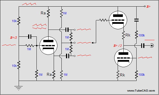
In the schematic above, we see a simplified circuit that reveals the same mode of operation as the more complex circuit. No matter which position the switch that connects the cathode follower is in, the same 50% of the rail noise is presented to the Aikido cathode follower. This cathode follower then bucks the noise with its own equal tugging because of the signal presented to its bottom triode's grid. The result is like the simpler Aikido amplifier: a greatly improved power supply rejection at the output.
Why use a switch? The switch allows us to select one of three positions: inverted phase, mute, and non-inverted phase. The mute in between is critical, as the ear needs a slight pause between phase reversals to reorient itself. Try this experiment: have friend quickly toggle the switch from inverted to straight. You are unlikely to hear any difference. Now, try taking a three-second muted pause between phase reversals. Now, what do you hear?
Alternatively, we can use this front end to feed a fully balanced output. In the schematic below, we see a suitable configuration for balanced output, making this an unbalanced-to-balanced line stage.
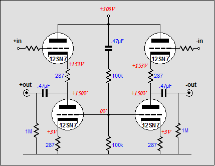
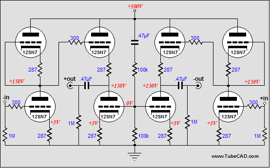
In the schematic below, we see a fully balanced line stage: balanced in and out. Note the shared noise injecting circuit, but the lack of any other shared cathode resistors. The result of such a separation is that the amplifier does not offer any common-mode rejection of shared, in phase signals, such line noise. True, any such signal will amplified in phase, so that it may be rejected further down the line by the next balanced amplifier.
If true 600-ohm driving capability is needed, then the circuit should be modified as follows.
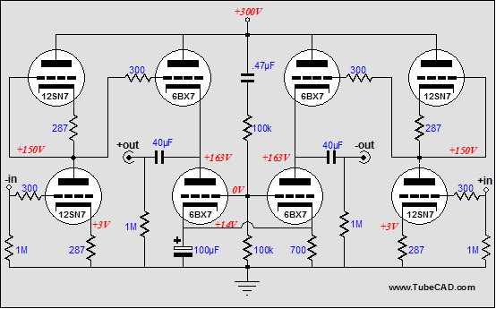
The 12SN7s have been replaced by 6BX7s at the outputs and the bottom 6BX7s now share a common bypassed cathode resistor. Because the common cathode resistor is bypassed, there is no real signal coupling between these two tubes—but as they undergo a balanced current swing, the bypass capacitor is greatly relieved of doing any hard work, as a nearly constant current flows through the common resistor.
Well, I think I am getting better at short. Now, let's see what I can do with often.
//JRB
|
|
|
|
Kit User Guide PDFs
Click image to download


TCJ PPC Version 2 Improvements
Rebuilt simulation engine
Create reports as PDFs*
More Graphs 2D/3D*
Help system added
Target idle current feature
Redesigned array creation
Transformer primary & secondary
RDC inclusion
Save user-defined transformer definitions
Enhanced result display
Added array result grid
*User definable
TCJ Push-Pull Calculator has but a single purpose: to evaluate tube-based output stages by simulating eight topologies’ (five OTL and three transformer-coupled) actual performance with a specified tube, power supply and bias voltage, and load impedance. The accuracy of the simulation depends on the accuracy of the tube models used and the tube math model is the same True Curves™ model used in GlassWare's SE Amp CAD and Live Curves programs, which is far more accurate than the usual SPICE tube model.
Download or CD ROM
Windows 95/98/Me/NT/2000/XP
To purchase, please visit our Yahoo Store:
|

