| John Broskie's Guide to Tube Circuit Analysis & Design |
23 December 2004 Murray amplifier Before going into the circuit’s explanation, I must give credit (for revealing the circuit to me) to reader, Phil, who wrote me last year: Firstly, thank you for a terrific journal. I found you about nine months ago and, having started my interest in electronics at a tender age building valve amplifiers (mostly using 6BQ5's and 6GW8's), I'm a great fan. My real job is manufacturing surface mount equipment so this is a kind of therapy!
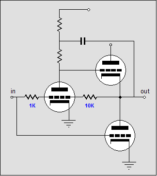
A simplified version of Murray’s amplifier is shown above (ignore the DC relationships). Starting with the bottom triode, it receives an input signal directly and amplifies and inverts the signal at its plate. The top output triode receives is input signal from the inverting triode-based gain stage, which in turn receives its input signal from the same source as the bottom output triode and from a feedback resistor that connects to the amplifier’s output. In other words, the top two triodes define a single two-stage inverting amplifier with a negative feedback loop. Below is a further idealized schematic of the Murray amplifier that helps make this point. 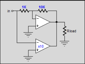
By carefully selecting the feedback resistor’s value, this two-stage inverting sub amplifier’s gain can match that of the bottom output triode, ensuring a balanced push pull operation. Well, that’s the hope, at least. Few loudspeaker present a flat impedance, which is what this amplifier needs to maintain perfect balance. Although to be honest, perfection lies outside of the world we live in and is probably overrated anyway. Since the top sub amplifier holds a much lower output impedance than the bottom output triode, the top amplifier will overwhelm the bottom triode in a tug of war, much like the Gomes amplifier. The sub amplifier’s feedback loop encompasses the bottom triode’s plate, allowing the top sub amplifier to clean up the bottom triode’s distortion, much like the Sandman circuit. The net result is that Murray’s amplifier doesn’t neatly fit in any typical amplifier class of operation category, as the top output tube is unlikely to ever completely cutoff, constantly drawing at least a trickle of current. The bottom output triode, on the other hand, can be driven in to complete cutoff. So what do we call such a mode of operation? Class-A/class-AB? (I can imagine what a high-end audio marketing department would call such an mode of operation: Pure Gold; all the advertising hype of class-A without the expense or heat of class-A.) Murray’s original paper on his amplifier is available at one of the best tube-related web sites, WIM'S DIY PROJECTS FOR AUDIO by Wim de Haan from the Netherlands. What if the asymmetry could be removed and the top and bottom output tubes equally matched? One step in that direction would be to give the bottom triode its own extra gain stage and feedback loop. Such an addition would allow the bottom triode to equal the top triode in output impedance and distortion. Furthermore, a closer approximation to balance push pull operation could be attained. What would such an amplifier look like? Below is one possibility (once again, ignore the absolute DC relationships; just look for the general idea). 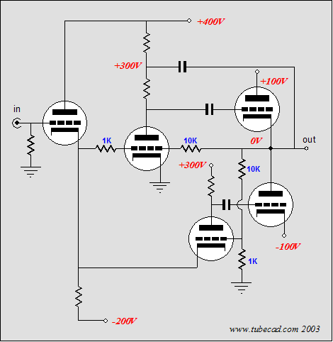
The input tube forms a cathode follower that provides a low output impedance, which is needed to drive the bottom output triode’s gain stage amplifier, as it is a grounded grid amplifier, with a low input impedance. This gain stage does not invert the input signal, which allows its output triode to invert at is plate. A negative feedback loop attaches from the amplifier’s output and ground, with the bottom gain stages’ grid receiving the error signal. The top of the amplifier works as before, excepting the cathode follower input stage. (The capacitor that spans the output to the top of the plate resistor serves to bootstrap the top gain stage, allowing a bit more gain to be realized. Sorry, I should have mentioned it earlier.) Still, the asymmetry of input impedances between top and bottom gain stage is irksome. The top gain stage’s input impedance is roughly equal to the 1k resistor’s value, whereas the bottom gain stage’s input impedance is roughly equal to (Ra + rp)/(mu + 1), which is further reduced by the feedback loop. What if we fed this output stage a balance input signal? 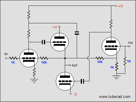 The Australian amplifier Now we do not need to use a grounded-grid amplifier for the bottom output triode. In the schematic above, both top and bottom gain stages use grounded-cathode amplifiers. In this circuit, the top gain stage’s input resistor (1k) is matched by bottom gain stage’s grid resistor. (Of course, different values could and probably should be used.) Since every topology must have a name, let's call this the "Austrailian Amplifier." PS 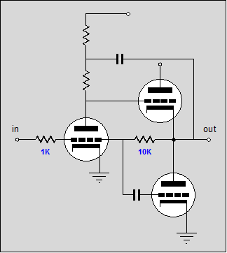 If you would like to see a photo of the amplifier that reader, Phil W., built, click here. Merry Christmas and happy New Year. //JRB |
Only $12.95
|
|||


| www.tubecad.com Copyright © 1999-2004 GlassWare All Rights Reserved |