| John Broskie's Guide to Tube Circuit Analysis & Design |
Mixed-Technology
|
||||
09 February 2005 Mix-tech hybrid (Speaking of blogs, I understand that the word “blog” was the most looked up word at the dictionary web sites last year. To be frank, I am not altogether sure this counts as blog, as what I publish is generally too long and too infrequent. By the way, 15,000 new blogs are started each day. How many cover tube circuits.) So, where are the tube circuits? I have been evaluating the mixed-technology hybrid amplifier, wherein the output stage holds both tube and solid-state output devices. First of all, what a curious mix this is. In the typical hybrid amplifier, the front-end is tube-based and the output stage solid-state, or vice versa. But not always, sometimes dissimilar technologies are used within a given amplifier stage, say the use of the solid-state constant-current sources to load a tube’s plate. So too, in a power amplifier, when the output devices differ in fundamental technology, one device plays a relatively passive role, acting as a constant-current source. However, in the schematic below, we see both output devices actively delivering a varying current into the loudspeaker. 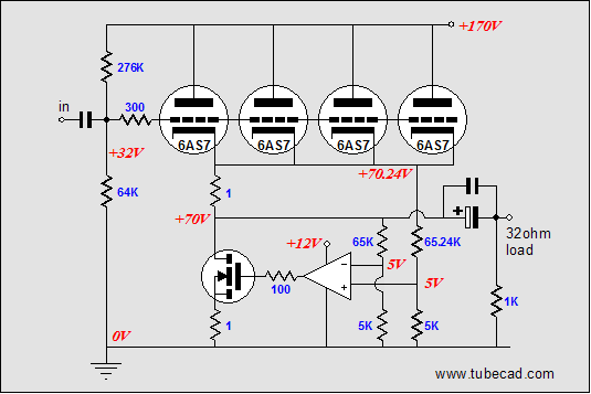
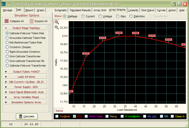
A quick overview: Only a single-polarity power supply is used, one that can readily be derived from rectifying a 117-volt secondary; and no voltage doublers are used. The four 6AS7 triodes receive 100 volts of the available B+ voltage; the MOSFET, the remaining 70 volts. (This ratio can be readily altered to give the triodes more voltage, as the output voltage swing will never approach 70 volts (300W into 8 ohms, by the way). The heater power supply offers 12 volts to both the 6AS7 (two in series) and the OpAmp, which both drives the bottom MOSFET and controls the output stage’s idle current. The output is capacitor coupled (the price we pay for having a mono-polar power supply; a good deal actually). The load is specified as 32 ohms (21W), but an 8-ohm load (12W) can be driven at a lower output power level.
This mixed-tech output stage needs a carefully designed input and driver stage. Because the 6AS7s require so much drive voltage to deliver their maximum current swing, a solid-state front-end isn’t our first choice, although one could be designed. The front-end must hold a gain of least 80, just to drive the output tubes, assuming a 1-volt input signal; and if a feedback loop is used, a gain higher than 80 will be needed. In other words, one triode is not likely to work, but one pentode might (or two triodes cascoded). However, two triode-based grounded-cathode amplifiers cascaded would gives us the most options, considering the low B+ voltage. For example, 6DJ8 type tube could easily deliver a final gain of 400 in such a circuit. 6DJ8???? One reason the 6DJ8 is so often used is that it works well with low voltages, because of its high perveance. The other reason it is so often specified is that I know the tube’s plate curves intimately, so I don’t have to look up grid voltage or cathode resistor values. But if asked what I think of the 6DJ8 as a tube, my answer is that it can be a real pain, as so many are microphonic. Fortunately, I own a hundred of them (scores of Siemens and Amperexs) that I can hand select good ones. But, so as not to offend the overly sensitive, let us use a 6N1P instead. Below is a one possibility. 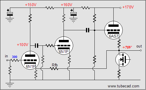
The low B+ voltage is partially setting the limit, as 74V times two is 148V, which barely fits in the 160-volt B+ voltage. In other words, if a 10k plate-load resistor were used (a typical value), the triode’s rp should not exceed more than 810 ohms. Since the 6N1P’s rp is closer to 15k at 50 volts, a 185k plate would be needed, which in turn would necessitate a miniscule idle current (never a good idea). Thus, the other limiting factor is the 6N1P itself. Yes, indeed, the 6N1P is a great little tube. It is quiet and it offers a fairly low rp. However, it is not a 6DJ8, 6922, 7308, ECC88 drop in replacement. It differs in mu, gm, rp, and heater current draw. Furthermore, one key difference a designer quickly finds is that it requires a higher plate voltage than the 6DJ8 type, because of its lower perveance. 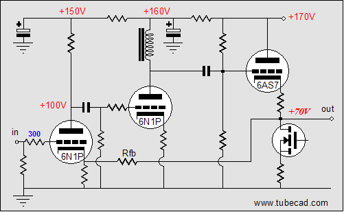
One workaround would be to replace the plate resistor with an inductor, which would effectively double the B+ voltage. Such a replacement would give the 6N1P plenty of voltage to work with, as almost the full 160 volts would be available. However, such a move is dangerous when a global feedback loop is added to the mix, as the inductor brings its own set of problems, such as resonance and phase shifts, which can easily turn an amplifier into an oscillator. Thus, in this circuit, with this limited B+ voltage, it should be obvious that the 6DJ8 is a better choice, but let us see if we cannot make the 6N1P work through a special technique. 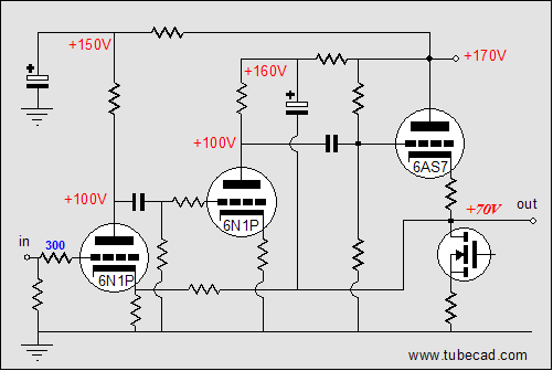 Bootstrapping 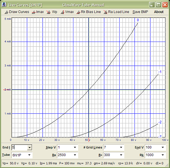
With a 37k plate resistor and an idle current of 1mA, the 6N1P would work, but this is still a trivial amount of current. Now, let’s see how well the 6DJ8 works. 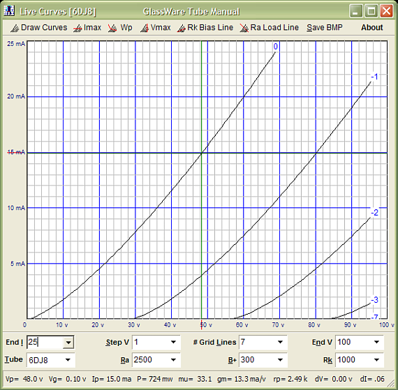
The 6AS7 is not linear a tube. —I have been told that some believe that it is a close relative to the 2A3. How so? Well, it looks like a 2A3 and the same company that created the 2A3 created the 6AS7. Sure, just as George Bush is a close relative to John Kerry, as both are white men that went to Yale. I would love to know who started this nonsense. The 2A3 is nothing like a 6AS7, as they differ in every key electrical characteristic and even in fundamental construction, as one holds a directly heated cathode and the other indirectly heated cathode.— And its nonlinearity shows with a brutal 128-ohm load-line (32 times 4, as there is four triodes working into a 32-ohm load). In other words, it only takes 38 volts (from grid to cathode) to completely turn on the 6AS7, but it would take closer to 50 volts to turn it off. A feedback loop will work to create this asymmetrical drive signal in the process of straightening out the 6AS7. Using a 6DJ8 with a plate resistor of 16k and an idle current of 5mA allows us to lower the plate voltage at idle to 116 volts, which will allow the 6DJ8’s plate to swing +80 volts and –96 volts relative to ground and +54 volts and –60 volts relative to the output, because of the bootstrapping. Therefore, in this circuit, a 6N1P is definitely not a drop in replacement for the 6DJ8. Of course, if we use a higher B+ voltage for the input and driver stage, then a 6N1P could be profitably used. //JRB |
Support the Tube CAD Journal TCJ Push-Pull Calculator

TCJ PPC Version 2 Improvements Rebuilt simulation engine *User definable
Download or CD ROM For more information, please
visit our Web site : To purchase, please visit our Yahoo Store:
|
|||


| www.tubecad.com Copyright © 1999-2005 GlassWare All Rights Reserved |