| John Broskie's Guide to Tube Circuit Analysis & Design |
09 September 2005
Speaking of email My good friend, John Atwood, has lent a hand and he has detailed several steps to help sort out the problem of junk email. For example, if the word “tube” appears in the subject line, the email will be considered good. So… is everything taken care of? No. While the steps I have taken have helped a great deal, the new problem is that my ISP’s resident web-based email program screws up. For example, in the morning, I’ll see a list of 1,000 emails, with 98% lined through, as they failed to pass the email filters. I then press the “nix the bad emails” button. This usually works, but not always; sometimes the truncated list holds only spam emails and all the good ones are gone. Just the other day I saw one with “To tube or not to tube” in the subject line; but it did not make it, even though it was not marked for deletion. (Please, whoever you are, resend it.) Why not junk the ISP mail program? I could, but then I would have to download all the thousands of erroneously returned junk emails and filter them on my computer which, even with DSL, could take forever. The solution might be to change my email address every other month, which would be a pain, as get email from some friends only every other year. An added problem is that someone is using @ the email address, as they mail out a million spam emails selling Viågrą (sic) or Rolexx (sic) watches; for example, drbill@glass-ware.com or thdwyppt@glass-ware.com as the return email addresses. Then the ISPs that receive these emails send me a notice that the recipient does not exist or that I sent spam and return the emails that I never sent; this is what now makes up the 1,000 emails in the morning. They are legitimate emails from good ISPs, but they have nothing to do with me. 
The best solution, as I see it is to get the Mafia involved. Doctors and layers often work for free to help out the needy: pro bono, as they say, i.e. done (without compensation) for (the public’s) good. Could not organized criminals do the same? With their network of contacts, and with their lack of legal impediment, they could easily locate spammers and virus creators who elude the police (some spammers are even famous and rich, as a result of making life miserable for others). Then, much like the KGB, which used to leave calling cards in the form of grotesque, signature execution murders (hollow-point bullets in the face) that would say loudly “We did this and it could also happen to you,” the Mafia types could kill spammers by using a can of Spam and sledge hammer. The message would be quickly understood, although Spam sales might suffer at the food store. No more than a modest proposal. 
The punch line is if you emailed and didn’t get a response, send it again and make sure to put “tube” in the subject line. I might be able to send these emails to a separate folder and save them from deletion.
Jeb’s amplifier
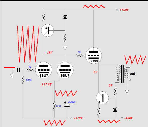
Before leaving the topic of cathode-follower output stages with bipolar power supplies, let’s look into a circuit that reader, Jeb, designed. His single-ended amplifier uses a single coupling capacitor at the input and DC couples the input stage to the output tube’s grid. In addition, its output stage is configured in a parallel-feed arrangement, with the cathode connected to an output transformer and to a solid-state constant-current source. In Jeb’s amplifier, all the gain comes from two 6SU7 (AKA, 6SL7) triodes in parallel, which are loaded at their common plates by a solid-state constant-current source. An interesting idea isn’t it? Only one coupling capacitor, solid-state constant-current sources, and parallel-feed. Well…
Jeb’s amplifier is a perfect example of an amplifier that will function flawlessly in a SPICE simulation, but fall flat in reality. How so? In SPICE, the power supplies are perfect, neither exhibiting noise or impedance, capable of delivering near infinite current at a constant voltage; reality disappoints, as all real power supplies hold some noise and offer frequency dependant output impedances. Furthermore, in SPICE, resistors, capacitors, and inductors are perfect, ideal in every respect, each holding none of the other’s attributes; all zeners are perfectly accurate and quiet; all tubes of the same type are perfectly matched in gm and rp; and temperature-induced bias shifts are unknown; and these tubes require no warm-up time before they can conduct; and, amazingly enough, SPICE tubes can even generate a current flow in the absence of any power supply—once again, reality disappoints. Unfortunately, Jeb’s amplifier requires a SPICE-like perfect world to function in. For example, imagine that the input is shorted to ground and that the bipolar power supply holds only 1V of noise on each rail (which is less than 1% ripple, after all). What happens? The noise on the negative rail will be amplified at the plate(s) by the mu of the input tube (70, in this example), as the input stage can now be seen as defining a grounded-grid amplifier, with the negative power supply rail functioning as a signal source. Thus, 70V of amplified noise will be presented to the 6C33’s grid. All most audiophiles would complain because of the 7V (almost 4W) of noise delivered to the 8-ohm loudspeaker.
The workaround to this problem is to terminate capacitor, C2, into ground, not the negative power supply rail; this will mean that a high-voltage bypass capacitor will be needed and that the capacitor’s polarity must be reversed. 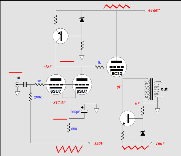
Well, is the amplifier perfect now? No, as the next problem to fix is the drifting DC offset. Why would the output drift? As the wall voltage drifts, the rail voltages will drift as well, climbing and falling with the alterations. But as the input and output stages are loaded by constant-current sources, the cathode-to-plate voltages must shift with changes in rail voltage. On the other hand, if the constant-current source were replaced by mere resistors, there is a chance that the DC offset might hold steady, as the tubes would increase in current conduction, as would the resistors, thereby canceling the rail voltage variations. Why is DC offset important? Unless the output transformer holds an air-gap, the output transformer will saturate in the presence of a sustained DC current. This is particularly true in the case of nickel-core transformers. The workaround might be to add a DC servo loop to the amplifier, which would monitor the DC offset and adjust the input stage’s output voltage accordingly. So, would the amplifier be ready to go now? Well, no doubt it would good enough for many high-end manufacturers, but it would still hold potential problems. For example, what happens at startup, when the tubes are cold? Will the 4mA constant-current source force the 6C33’s grid to climb to +160 volts, while the 6SU7 heats up? What will happen if the 6SU7 fails or is pulled from its socket or just giggled a bit? Will the 6C33 instantly draw several amperes of current, damaging the output transformer along the way? What if the 6C33 fails or is missing from its socket? Will the sustained 300mA damage or severely magnetize the output transformer’s primary? In other words, although often expensive and sonically intrusive, coupling capacitors can save you from many headaches. If we add a coupling capacitor to Jeb’s amplifier—in between the output tube and the output transformer—we will not really need a bipolar power supply. In fact, we do not really need the input coupling capacitor and we might be able to get rid of the input stage’s cathode bypass capacitor, which was a stealth coupling capacitor, as all the audio signal had to travel through it; and few 100µF electrolytic capacitors sound anything but bad.
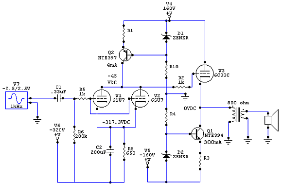
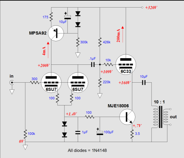
The above schematic shows the mono-polar-power-supply version of Jeb’s amplifier. The first stage no longer DC couples to the output tube, but the added coupling capacitor saves the day, should the 6SU7 fail or be absent. The coupling capacitor that connects to the output transformer must be large enough in value to allow a decent bass extension—with a reflected impedance of 800 ohms, anything value above 10µF would set a high-pass transition frequency below 20Hz. The idle current through the 6C33 has been reduced to a sane 200mA, which will yield a sane 33W of dissipation and larger output voltage swing. (Jeb was planning on using a DAC that holds a 2.5V DC offset at its output. The DAC could still be used, if a bypassed cathode resistor is added in a value sufficient to displace the 2.5V bias voltage.) So is this the perfect amplifier? Perfect for what? Is my standard answer, which just angers those who seek absolutes, absolute answers independent of context. How about we rephrase the question to Is this amplifier an effective way to get several watts of clean single-ended amplification, with a low output impedance and no global feedback loop? The answer is that it is probably a much better amplifier than is sold in many high-end boutique stores. Still, it is not as efficient as it could be. 
The output tube is loaded by both the output transformer’s primary impedance and by the constant-current source. The latter is the cause of the lower efficiency, as a the theoretical maximum efficiency of a class-A, constant-current source-loaded amplifier is only 25%, whereas an inductively loaded class-A amplifier’s theoretical maximum efficiency is 50%. Do not forget that theoretical maximum efficiency is never attained in tube equipment, that actual efficiency will probably be only half of the theoretical limit. In other words, with the constant-current source load, the amplifier can put out about 8W; with an inductive load, 16W.
//JRB |
Only $12.95
Download or CD ROM www.glass-ware.com
|
|||


| www.tubecad.com Copyright © 1999-2005 GlassWare All Rights Reserved |