19 September 2006
They're Back
...and
There are three topics that that provoke a big e-mail response: tube phono stages, tube headphone amplifiers, and tube shunt regulators. This website could devote every word and schematic to these three topics (and only these three) and 80% of its readers would be ecstatic. Unfortunately, an Aikido-based phono preamp would require two Aikido amplifiers (four tubes per channel) and a shunt regulator could never be built from the Aikido topology. That leaves an Aikido-based tube headphone amplifier. Unlike the other two, this project is easily doable; in fact, many have built headphone amplifiers with the existing Aikido PCBs. So I started thinking about what would need to change to make headphone-amplifier friendly Aikido boards.

The cloud that looms big over such a project is that the Aikido cathode follower is a pure single-ended affair. Single ended operation is glorious, but limited. Unfortunately, sonically wonderful as single-ended mode undoubtedly is, it cannot provide the larger voltage and current swings of a comparable push-pull output stage. Why? Single-ended stages can only deliver up to the idle current into a load, whereas class-A push-pull stages can deliver up to twice the idle current; and class-AB output stages can deliver many times the idle current. For a line stage, big voltage and current swings are seldom required; headphones, on the other hand, do demand a lot more power. In all truth, a 32-ohm load is brutally low impedance for any tube to drive.
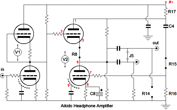
I went to work, modifying the mono 9-pin PCB so that it could be optionally configured to hold a White cathode-follower stage, while still retaining the Aikido’s great low distortion and superb PSRR, but allowing twice the idle current to be delivered into low-impedance loads. In other words, with new PCB, by adding a resistor and capacitor and removing a few resistors, creates an excellent Aikido headphone amplifier. (The new boards also now include many ventilation holes that keep the output tubes cool and they accept a bypass capacitor for the bottom triode's cathode resistor.) Beyond these small topological alterations, a high transconductance output tube should be used, for example, the 6DJ8, 6H30, 12BH7, ECC99; and a large-valued coupling capacitor of at least 30µF is required when driving 300-ohm headphones and 300µF for 32-ohm headphones. The new resistor is R17. Its value is critical, as it sets the balance between top and bottom triodes and it ensures that the power-supply noise is purged from the output.
There is a lot more information in the new revision-A PCB user guide (10 pages). The price remains the embarrassingly low $24 USD per board. The boards are available at the GlassWare Yahoo store. By the way, I can accept PayPal, if you do not have or like to use a credit card on the net. Just e-mail a list of what you want and I'll send you a PayPal invoice; once I receive the funds, I'll send the order out.
Although much of what follows was covered in the blog entries on single-ended, cathode-follower power amplifiers, it is worth hammering home again. First the big fallacy: since a cathode-follower-configured amplifier presents a low output impedance (Zo), the output transformer’s primary impedance must be equally reduced, which would allow the use of 300-ohm primary instead of the 3,000-ohm primary usually needed for a 2A3-based push-pull amplifier, for example. This false conclusion is as seductive as it is false.
The output stage topology does not alter the tube’s intrinsic characteristics. Operating the output tubes in a cathode-follower configuration does not change the current-voltage dynamics that the tubes must undergo. The tube’s rp, mu, and gm remain unchanged, as the output tube is indifferent to what circuit topology in which it finds itself. Therefore, use the same primary impedance that you would use in a grounded-cathode, push-pull power amplifier.
One way to understand what is going on in a cathode-follower-configured amplifier is to compare it to a grounded-cathode amplifier power amplifier that uses feedback to produce an equally low output impedance and distortion figure. The grounded-cathode amplifier’s input and driver stage develop a cumulative gain of 400, so that a 1Vpk input signal magnifies into a 400Vpk drive signal. The output tubes, however, never see 400Vpk signals on their grids, as the feedback loop limits the drive signal to 40Vpk. In other words, in the absence of the feedback loop, the amplifier would only need a gain of 40 from its input and driver stages to achieve full output. That ten to one ratio in reduced drive signal represents the same ratio of reduced Zo and distortion.
Now, in contrast, a cathode-follower-configured power amplifier forgoes the global feedback loop, as the output stage holds its own feedback mechanism. The output tubes' cathodes and grids enjoy 100% degenerative feedback. In other words, any deviation the cathode takes from the grid’s course results in the output tubes bucking that deviation by increasing and decreasing its conduction to counter the wayward movement. The price we pay is that the cathode-follower output stage provides no gain and it requires a huge drive signal, in this case, a 400Vpk drive signal.
Note the similarity between the two amplifiers. Both require an input and driver stage gain of 400 and both offer a tenfold reduction in Zo and distortion and both use a feedback mechanism to achieve these goals. They differ in how the feedback is applied. Wait a minute. Isn’t all feedback vile and despicable? Shouldn’t we be turning our back on all feedback? Well, as I have mentioned before, if that is our goal, then we have to throw away our 2A3, 6SN7, 300B, 211, and 845 collections, as just being a triode means feedback in the form of plate resistance; and all cathodes must be attached to ground either directly or through large bypass capacitors, otherwise local degenerative feedback will take hold. Sorry, but like a country without police and jails, I wouldn’t want to go there.
The feedback loop realized in a cathode-follower-configured power amplifier is short and fast; it doesn’t have to snake through dozens of parts or transverse through the output transformer’s core. The reason that tube amplifiers have held such low feedback ratios compared to their solid-state brethren is because tube amplifiers had no choice. An extra gain stage (in other words, one more tube) would increase the feedback ratio by the gain of that stage; but such a tube amplifier would oscillate wildly, as all the phase shifting stages would return a positive feedback signal, not a negative one. Forget all the pop psychobabble about the glories of positive feedback; in amplifiers, positive feedback is dangerous.
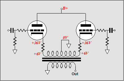
The simplest and possibly, the best method to set the idle current in a cathode-follower, push-pull amplifier is to use one cathode resistor per output tube. The un-bypassed resistors increase the linearity of the output tubes at the cost of a slightly higher output impedance and greater drive signal. As shown below, the output transformer’s primary DCR must be added to the mix, as the DCR will also displace voltage in the presence of current.
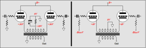
Other biasing arrangements are to use a common cathode resistor or fixed bias. The common cathode resistor will see little current variation in a true, honest-to-God, class-A amplifier, but will see huge current variations in a class-AB or class-B amplifier. One workaround is to place a zener in parallel with the common cathode resistor; the zener must be selected to break at a voltage slightly higher than it sees at idle; for example, 33 volts when the idle voltage across the common cathode resistor is 28 volts. Fixed bias requires a negative power supply rail. Because the output transformer primary holds a relatively high DCR, no cathode-follower, push-pull amplifier can be purely fixed bias, as the primary’s resistance defines an effective cathode resistor.
The biggest problem to overcome in cathode-follower, push-pull amplifier is providing the output stage with a huge-but-clean drive signal. Several hundred volts of clean signal are needed. Yes, tubes love voltage, but 400Vpk swing is huge and difficult to achieve without distortion. In the schematic below, we see a grounded-cathode amplifier cascading into a split-load phase splitter, which in turn cascades into two parallel grounded-cathode amplifiers. (The two plate resistors help limit voltage-induced distortion in the resistors.)
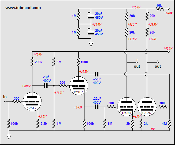
Using 6SL7s and 6SN7s results in a final gain of roughly 270, which is enough for 2A3s, but not enough for most of the bigger output tubes. Using a 12AX7 as the input tube and a 5687 as the driver tube will provide more gain and larger voltage swings due to the 5687’s lower rp.
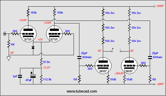
A different approach is to use a bipolar power supply. Such an arrangement allows us to use my electrostatic headphone amplifier as the frontend. An added bonus lies in the option to drive electrostatic headphones by cutting the heater voltage to the output tubes. Imagine how delicious it would be to be able to choose between Stax electrostatic headphones and 300Bs.
The schematic below shows an unbalanced input. This circuit has been covered before, so I won’t explain the noise-canceling tricks I have included. But I will remind my readers that a constant-current source would not be an upgrade, as it would greatly compromise the noise from the driver stage’s outputs. Another danger is the attractive nuisance of direct coupling of the driver stage outputs to the output tubes’ grids. Don’t. Don’t even think about it. Why? What happens at start up when the output tubes are cold? The grids will see the full B+ voltage, while the cathodes will be at ground potential. Not a good idea.
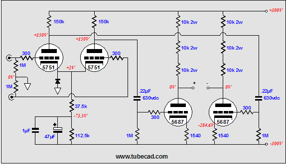
Configuring this frontend to accept a balance in signal is easy. As a bonus, using a balanced input signal will double the gain of this frontend.
//JRB
|


