| John Broskie's Guide to Tube Circuit Analysis & Design |
|
21 May 2007
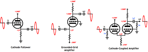
Welcome to the HTLM version of the Tube CAD Journal. Yes, it’s true, I am back to posting both a PDF and a HTML version. Why? (Believe me, I as ask myself the same question.) The answer is better printing. As I have mentioned before, this website gets printed by many of its readers. (Now, if only I could get a kickback from the ink and toner manufacturers.) I have read that a 6-inch ream of paper is not enough to print the whole site! That’s a lot of paper, a lot of schematics, and a lot of words. Just the other day, I printed blog 107 and I was shocked. It took five pages of double-sided paper and the word count was nearly 2,500, which is 2.5 times longer than the standard 1,000-word article that magazines print. No wonder that it takes so long to post a new blog entry. (Interestingly enough, after writing the blog, my perception of what I had produced is about a third of what I had done, maybe four pages and certainly less than 1,000 words.) Well, let’s see if I can keep it under 1,000 words this time. Additionally, let’s see how the schematics turn out. My hope is that they are more legible and print more cleanly. Let me know if it is otherwise. Schematic Typo An observant reader spotted a schematic error I had posted in Blog 107 (thanks Steve). I was trying to illustrate the distortion shape for the cathode follower, the grounded-grid amplifier, and the wedding of the two circuits, the cathode-coupled amplifier. I got the distortion shape right, but not the phase; both the cathode follower and the grounded-grid amplifier preserve the phase of the input signal at their outputs. Below is the correct graphic.
The key point remains that the cascading of two distorting circuit can produce less distortion, which the cathode-coupled amplifier nicely establishes.
Zune Survey Recommended Cathode-Coupled Amplifier Circuits I know that many who find this website through Google searches quickly get lost in it; there is just an enormous amount of material. I can usually spot e-mail from these readers. It isn’t hard, as they often begin with asking which guitar amplifiers or microphone preamps I sell. Or they ask a question that the previous blog was entirely devoted to answering. But then there are a few readers—who might have seen my name mentioned at another website or forum—that read this blog in hopes of finding the elusive solution to their audio problem, the problem of acquiring the best. They rapidly lose patience with my flood of circuit variations; they long for one circuit, and only one circuit, the Absolute Circuit (hey, what a catchy name for a website, www.TAC.com too bad it is already taken). They only want to see the best circuit. They want the answer—not more questions—and they want it now. The source of this urgency is both interesting and saddening. For many audiophiles, their stereo is not just the means by which they can listen to music; rather, for them it is a vindication, a stamp of approval, a testament to their own superior discernment and refinement. Thus, an expansive sweep of possible circuits, without hype and the hard sell, is for these audiophiles, as useful as an honest used car salesman or a critical and judgmental therapist. In the land of consumption, those who consume the best are the best, as you are only as exalted as your consumption. So why don’t I exalt only the best circuit, best tube, best plate resistor…? To be honest, I haven’t received a request asking me to name the best tube or plate resistor value in the last two years (I always answer with something silly such as a 36MG4 and 51.37K). But I do get a few asking what circuit would sound better than some current rave product like a Tube Glow Dynamics Model 8A-4, which invariably I have never heard of let alone listened to. Needless to say, “better” is seldom specified—you know, just better. On the other hand, if asked what I would build, then I have no problem narrowing twenty circuits down to two or three. Thus, what follows are the cathode-coupled amplifier circuits what I would most like to build.
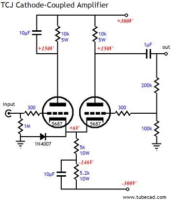
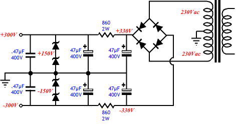
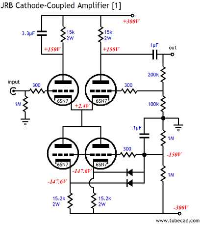
The Tube CAD Journal cathode-coupled amplifier shown above would be my first project. Why? Because it is simple, requires only two tubes (for stereo), and it promises some excellent results, as the circuit’s design goals are low distortion, low noise, and high reliability. The 5687 is a great and fairly cheap dual triode, but other tubes can be used, such as the ECC99, 6DJ8/6922, 12BH7, 6H30, or even the 12B4, although four will be needed. The 10µF shunting capacitors can be Solen or Dayton polypropylene film capacitors (or 47µF electrolytic capacitors). The 10k 5W plate resistors might be hard to find, although Caddock MP9 series Kool-Pak non-inductive power resistors would work nicely and they are available from Mouser. The idle current per triode is 15mA, so each plate resistor must dissipate 2.25W. Thus, a cheaper route might be to place two 20k 2W resistors in parallel. Each of the two cathode resistor resistors must dissipates a bit less than 5W, so four 2W resistors could be placed in parallel to replace each. Although the circuit provides its own PSRR enhancement via the bottom 10µF capacitor shunting the bottom cathode resistor, the power supply still needs to be fairly high quality. I would use FRED rectifiers and a 230Vac, center-tapped power transformer, which will yield about +/-330Vdc. A simple shunt-regulated power supply could be made using four 75V 5W zener diodes (1N5374B, for example) and two series voltage dropping resistors. The 860-ohm resistors will drop 30 voltage with 35mA of current through them, which means that the zeners see an idle current of 5mA and 0.75W of dissipation per zener. At startup, or if the tubes are pulled from their sockets, the zeners will have to draw the full 35mA of current, which will bring their dissipation up to 2.625W. Note that the line voltage need only sag by 10% to kill the shunt regulation and that if the wall voltage were to climb by 10%, the zeners would exceed their 66mA current limit trying to maintain regulation without the tubes sharing the load.
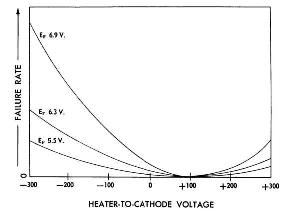
The heater power supply can be AC or DC, with the DC power supply the lowest noise. I would reference the heater power supply to +40Vdc. Why? The graph below is from Robert "Bud" Tomer’s excellent book, Getting the Most out of Vacuum Tubes. Here we see three plots for three different heater voltages, 5.5V, 6.3V, and 6.9V against the heater-to-cathode voltage.
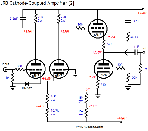
The interesting thing to note is that 0-volts does not yield the lowest failure rate. In fact, referencing the heater power supply to +80Vdc appears to result in the greatest reliability. Remember that electrons flow from negative to positive, so if the heater is positive relative to the cathode, the heater cannot develop any current flow to the cathode, whereas if the heater is substantially more negative than the heater, it would be almost impossible to prevent a current flow from heater to cathode. The second circuit that I would build would be the following, in spite of the two heater power supplies required.
I switched to 6SN7s/12SN7s just to pay homage to octals, but the 5687 or 6H30 tubes could be used instead. Actually, the cool tube to use might be a 6BL7 or 6BX7 or maybe a pair of triode-connected pentodes, such as the El84 or EL86 or 6V6.
This cathode-coupled amplifier uses an active load in place of cathode resistors. The effective impedance presented to the coupled cathode is over 160k, which counts as constant-current source in my opinion, as 10mA against 160k equals 3,200V. Furthermore, this close approximation to a constant-current source has been designed to inject just enough noise current into the plate resistor to null the power supply at the output. The two diodes are protection devices that fall out of conduction once the tubes are hot and conducting. The 200k and 100k two-resistor voltage divider defines a feedback ratio of 2:1, which result in a gain close to +10dB. This feedback loop will also lower the output impedance. If I needed a lower output impedance, then I would build the following circuit.
We are back to an Aikido version of the cathode-coupled amplifier. The cathode-coupled amplifier’s output contains about 50% of the positive power supply rail’s noise, which the Aikido cathode follower eliminates. If you thought that a cathode-coupled amplifier held a near-zero PSRR, you are right; but only when the cathode resistor has been replaced by a constant-current source or when the negative rail holds a perfectly clean voltage. In other words, the common cathode resistor attaches to noise-free cathodes and to an anti-phase noisy negative power supply rail. The noise induces a modulated current to flow through the top plate resistor, canceling half of the noise from the cathode-coupled amplifier’s output.
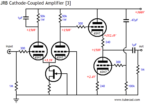
The seemingly superfluous resistors that bridge the negative to ground are there to equalize the current draw on each power supply rail. This will ensure the noise relationship with the positive rail will be of equal magnitude, but opposite phase. Of course, there will be many readers who do not like the idea of using a negative power supply rail or of using solid-state rectifiers. Well, if I were so inclined, then I would the build the mono-polar-power-supply version instead, which uses a single B+ voltage of 300V. In order to keep the distortion low, we must use a constant-current source to load the coupled cathodes. Although constant-current source ICs can be bought that work with only 5V across them, I would try to use a FET-based constant-current source instead, as I just might find a pair of FETs with IDSS of 6mA, the total idle current of one cathode-coupled amplifier.
Note that the tw0-resistor voltage divider that injects power supply noise into the bottom triode on the output stage has been replaced with a single resistor. Why? The constant-current source forces a near non-existent PSRR on the cathode-coupled amplifier, so the Aikido cathode follower must overcome all of the power supply noise presented to its input. Once again, the heater power supply should be reference to about +75V. And once again, many different tubes could be used. The only difficult part might be finding the right FET. (A low-voltage negative power supply might be the answer, say -10V.) Still, I love the look of this circuit, with its eleven resistors and three capacitors. No phase inversion, low distortion, low output impedance, low noise, super wide bandwidth, and no feedback loop.
Conclusion
//JRB |
Now accepting Support the Tube CAD Journal TCJ Push-Pull Calculator
TCJ PPC Version 2 Improvements Rebuilt simulation engine *User definable
Download or CD ROM For more information, please visit our Web site : To purchase, please visit our Yahoo Store:
The Tube CAD Journal's first companion program, TCJ Filter Design lets you design a filter or crossover (passive, solid-state or tube) without having to check out thick textbooks from the library and without having to breakout the scientific calculator. This program's goal is to provide a quick and easy display not only of the frequency response, but also of the resistor and capacitor values for a passive and active filters and crossovers. TCJ Filter Design is easy to use, but not lightweight, holding over 60 different filter topologies and up to four filter alignments: While the program’s main concern is active filters, solid-state and tube, it also does passive filters. In fact, it can be used to calculate passive crossovers for use with speakers by entering 8 ohms as the terminating resistance. Click on the image below to see the full screen capture.
Tube crossovers are a major part of this program; both buffered and un-buffered tube based filters along with mono-polar and bipolar power supply topologies are covered. Available on a CD-ROM and a downloadable version (4 Megabytes). Download or CD ROM
|
|||


| www.tubecad.com Copyright © 1999-2007 GlassWare All Rights Reserved |