| John Broskie's Guide to Tube Circuit Analysis & Design |
|
04 August 2007
MC Phono Pre-preamp
I once had lunch with an audio magazine editor. He told me that he gets several offers a day by eager audiophiles who want to write audio product reviews. He sneered, "As if it takes any talent to write an audio review; hell, give me four pieces of gear and four hours and I'll write four long product reviews. But if someone can write a decent article on how SACDs are mastered or the history of some great recordings or explain how Thai audiophiles are different from Chinese or Japanese audiophiles, then I am very interested." As far as I am concerned, it's the inclusion of schematics that separates the KT88s from 6BQ5s in audio magazines. Admittedly, the British magazine Hi Fi News will occasionally will publish technical articles that hold a few schematics and the late, and once great, Audio magazine used to display schematics (back in the 50s, 60s, and early 70s), when the product’s circuit was interesting enough to warrant it. (It is sad to remember what we once had in both audiocraft and Audio magazines.) And, no doubt, each modern glossy audio magazine would argue that its readers do not want to see schematics, that their readers love the non-technical and non-demanding fluff reviews, that they receive countless requests to eliminate the few technical overviews, tables, and graphs that they do publish, and that their readers are themselves "not technical." And if I didn’t know that it required a lot more intellectual wherewithal and effort to include high-quality technical explanations and idealized schematics, I would be more inclined to believe them.
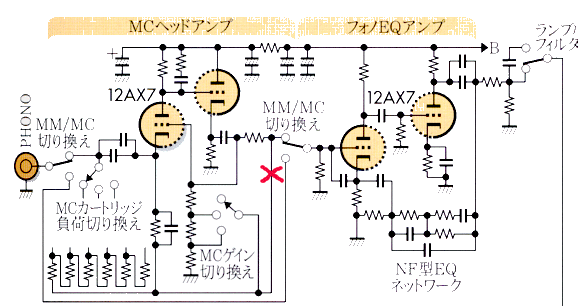
Well, in the 2007 Number 8 issue of MJ, we see a review of the Audio Space Reference Two phono preamp and line stage amplifier. This beautiful preamp from Hong Kong garners much fanfare because of its inclusion of four 300B triodes. Yes, four 300Bs in a preamp, but that is not what I found most interesting. Instead, I was intrigued by the use of a grounded-grid amplifier for an MC cartridge pre-preamp, before cascading into a conventional two-triode active-equalization phono stage. I have scanned the schematic and it is displayed below; unfortunately, it holds a schematic typo (the output is shorted to ground), which I have marked with a red X.
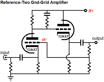
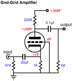
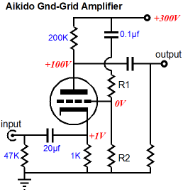
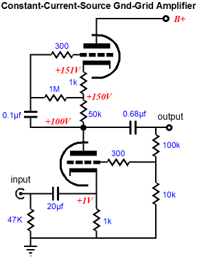
The following schematic is a simplified version of the above, without the RIAA equalization phono stage. But before we dive into this circuit, let’s do a quick overview of grounded-grid amplifiers. (By the way, I get flack for not calling a grounded-cathode amplifier a “common-cathode amplifier,” which would bring it in line with the common-emitter transistor amplifier. Well, should I also call the grounded-grid amplifier a “common-grid” amplifier? I prefer “grounded,” as I see “common” referring to something shared, not something grounded. And I am not even going to mention all the anguish the fans of Bruce Rosenblit’s grounded-grid amplifier are going to go through. Maybe I should just call it the KGP amplifier, as per my own recommendation.)
Grounded-Grid Amplifier Overview Okay--that sounds great, so why don’t we use the grounded-grid amplifier all the time? Once again, the big problem is the low input impedance. And let’s not forget that the cathode is not at ground potential, but at some positive voltage relative to ground. This means a coupling capacitor is needed at the input—a very large-valued coupling capacitor. For example, in the circuit above, the input impedance is around 700 ohms, which requires a coupling capacitor of at least 12µF to ensure a -3dB low frequency cutoff of 20Hz. Now how much does a 12µF Teflon or silver-foil and oil coupling capacitor cost? Moreover, don’t expect your CD player, tuner, and phono preamp to be happy driving a 700-ohm load impedance; nor will a 100k volume potentiometer work well when loaded by 700 ohms. Let’s assume that we are willing to pay the low-input impedance price: what can be done with this basic topology?
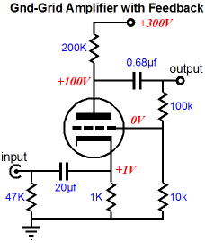
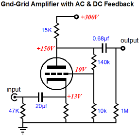
Well, we can easily add a feedback loop, which would lower the gain, distortion, and output impedance. The 12AX7 in the schematic above might realize a gain of 70 without the feedback loop, but with it, the gain falls to 10 (+20dB), which is plenty for many applications. (By the way, notice how the feedback signal is applied to the grid, which as we know offers an extremely high input impedance, but more curtailed bandwidth, due to Miller-effect capacitance; this means that the feedback mechanism will run out of steam at high-frequencies. This will prove important later on when we look at the Reference-Two circuit.) In the schematic above, the feedback loop only relays AC signal to the grid, not DC signal. If we move the feedback resistor string to the other side of the coupling capacitor, however, we can realize both AC and DC feedback.
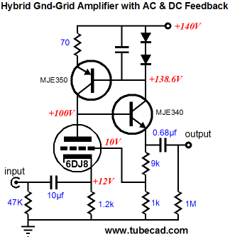
Note that the total number of parts remains the same; we just moved a few around. What good is DC feedback? First of all, we have eliminated the coupling capacitor from the loop, which means that its failings will not throw the amplifier into a tailspin. Remember, reactive components and feedback can go together, but only when great care is used and modest expectations are expected. Second, the tube’s aging will be compensated by the negative DC feedback, so the idle current will adhere more closely to its design target over the life of the triode. Where the DC feedback might prove particularily handy is a hybrid grounded-grid amplifier.
Because the DC operating points are stablized by the negative feedback, a much lower B+ voltage can be used. Imagine a small extruded enclosure with a single tube protruding from its top panel. “The monocle” MC pre-preamp would have a gain of +20dB and a relatively low power supply voltage and an excellent PSRR figure. Still, I can image many getting nervous with the turn to feedback, so let’s move on to a feedback-free design, an Aikido-like grounded-grid amplifier.
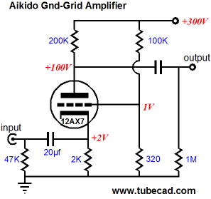
By carefully picking the values for resistors R1 and R2, we can inject a small portion of power supply noise into the grid, which will be amplified and phase inverted at the plate, where it will cancel the existing power supply noise. Since resistor R1 will be so much larger than R2 with most triodes, we can forgo the 0.1µF capacitor and allow the DC offset at the grid.
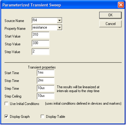
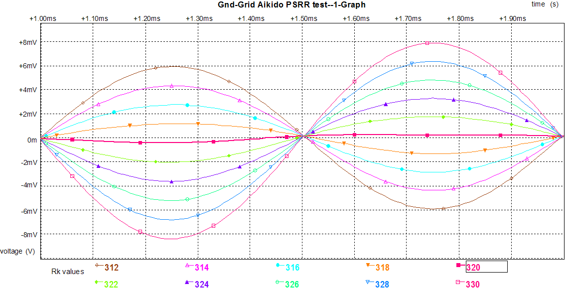
I ran some SPICE simulations and the above part values yielded the best PSRR figure. The following graph shows the results of a parameterized sweep simulation, with resistor R2’s value being the key variable.
With an R2 value of 320 ohms, the 1Vpeak of power supply noise was reduced to less than 1mV, which translates into better than -60dB of PSRR. Not bad. Before moving on to more complex circuits with two triodes, the only other useful variation I can think of would be a transformer-coupled grounded-grid amplifier.
The idea behind this circuit is that the transformer’s secondary holds enough DCR to substitute for a cathode resistor, with the assumption that the transformer holds enough of an air gap to sustain the magnetizing DC current flow. (The feedback loop was added as a freebie, but the Aikido-style two-resistor noise injection circuit could be used instead, as could just grounding the grid.
Two-Triode Grounded-Grid Amplifiers
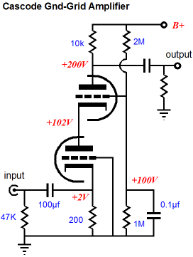
This somewhat-pseudo constant-current source presents a load impedance equal to the sum of the two top cathode resistors against the top triode’s mu + 1 (with its rp added to the total). In this example, it equals about 5M of impedance, which although not infinite, is still plenty high. Furthermore, when we add the feedback loop, the PSRR and distortion figures are enhanced even more. Another simple variation would be a cascode grounded-cathode amplifier.
The downside to the cascode amplifier is its poor PSRR. If only we could do an Aikido on the cascode....
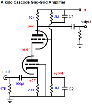
Capacitors C1 and C2 voltage divide the power supply noise according to the inverse ratio of their values, but allow the same DC voltage division to obtain. Sweet. But how do we select the right capacitor values? The first Tube CAD Journal issue held the answer in an article titled Improving the Cascode's PSRR. Now that we have done enough mental stretching, let’s move on to other two-triode grounded-grid amplifier circuits.
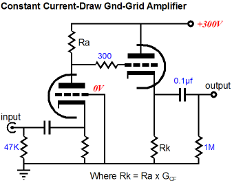
The above circuit may look simple enough, but it is quite powerful nonetheless, because it draws a non-varying current. This hugely relieves the power supply, as the input signal is not being superimposed on the B+ voltage, where it can recirculate to other stages. The secret to making it work lies in the right ratio between resistors Ra and Rk. Resistor Rk must be smaller in value than resistor Ra by the degree that the output cathode follower stage gain falls short of unity. In other words, if the cathode follower realizes a perfect gain of 1, then Rk = Ra; if the cathode follower can only muster a gain 0.5, then Rk = Ra/2.
Adding a feedback loop is easy enough, as shown above. And, of course, we could apply the Aikido-like two-resistor voltage divider network instead, but the above circuit will helps us jump to the Refence-Two circuit.
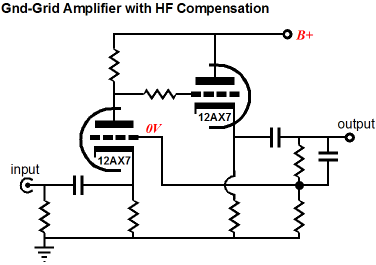
The Reference-Two grounded-grid amplifier circuit differs in two important ways: the feedback is taken after the coupling capacitor and the input stage is loaded with high-frequency compensation network. My guess is that the two are tied together. The resistor/capacitor network imposes a shelving function on the high-frequencies, where the gain falls off at -6dB per octave after same high-frequency and then flattens out at some higher frequency. Another common approach to taming an unstable feedback-laden amplifier is shown below.
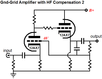
Instead of limiting the amplifier’s high-frequency response at the plate, the capacitor across the top feedback resistor limits the high-frequency gain by increasing the feedback at high frequencies, so that the feedback can remain in phase with the input signal. (Sometimes both high-frequency compensation techniques and others are used in the same amplifier.) Now, if the high-frequency problem lies with the coupling capacitor, whose parasitic inductance is limiting its high-frequency transfer, the added capacitor on the feedback loop may do no good. A simple workaround would be to move its connection to the other side of the coupling capacitor.
What intrigues me is the possibility that using the DC and AC feedback connection and a few grid-stopper resistors just might solve any high-frequency instabilities cold. By the way, I should mention that the grounded-grid amplifier has been used as an MC pre-preamp before: David Manly design such a circuit twenty-five years ago in one of his VTL phono preamps. And I should mention that the grounded-grid amplifier and MC cartridges go together quite well, as the cartridge's DCR is only a few tens of ohms. Remember a low-impedance input requires a low-impedance signal source. I had a lot more to write about concerning phono stages, but I had better stop here, as I am over my 1,000-word limit by about 1,000 words.
//JRB
|
Support the Tube CAD Journal & get an extremely powerful push-pull tube-amplifier simulator for TCJ Push-Pull Calculator
TCJ PPC Version 2 Improvements Rebuilt simulation engine *User definable
Download or CD ROM For more information, please visit our Web site : To purchase, please visit our Yahoo Store:
|
|||


| www.tubecad.com Copyright © 1999-2007 GlassWare All Rights Reserved |