| John Broskie's Guide to Tube Circuit Analysis & Design |
|
27 January 2008
24V Aikido Line Stage and Headphone Amplifier
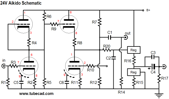
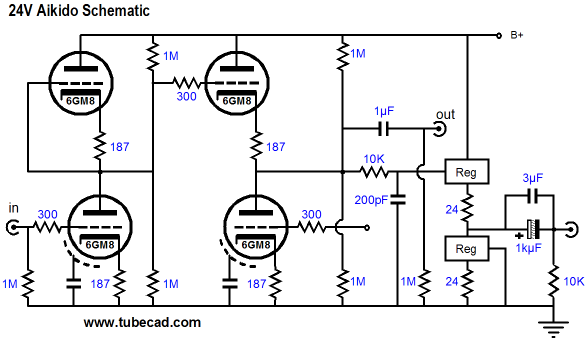
Well, in the last batch of PCBs I had made, I included a few new boards, one of which was custom tailored for the 6GM8 and a 24V power supply, as shown above. In addition, I added a class-A, single-ended, unity-gain, solid-state buffer output stage, for driving low-impedance headphones (32 to 600-ohms). Moreover, I included a spot for a large electrolytic power supply capacitor. Amazingly enough, the new board is only 1-inch taller than the old stereo Aikido boards. Below is a view that show the board stuffed with parts in a simple case.
(Before you e-mail me asking where I got the enclosure, I will preemptively say that I do not know how you can get one today; all that I remember is that I bought it two decades ago from some firm in Canada and that it was made in Asia. It is made from steel and is 4in tall, 12in wide, and 7in deep. It also came with a black, brushed, anodized, rack-mount front panel (and with two handles), which I choose not to use.) The power supply I used is so easy and cheap that it is almost embarrassing. It is a switch-mode, wallwart design from CUI Inc (EPAS-101W-24), which puts out 24V at 500mA. This unit is tiny, about half the size of a packet of cigarettes. And it, like most switch-mode power supplies, sparks quite a bit when it’s plugged in a wall socket. I also made up a linear, voltage-regulated, power supply for the 24V Aikido. This power supply actually put out 25.6V and it did sound a bit better than the cheap switch-mode power supply. What I would like to try, however, is an expensive (relatively speaking, $45 USD rather than $25) medical-grade switch-mode power supply. If nothing else, it probably is safer and less noisy. I did try a 24V/1.6A switch-mode power supply that I had and it sounded no worse or better than the 500mA unit.
What is missing is a power switch. (I might decide to use a power switch only to cut the power to the heater string, leaving the rest of the circuit energized, which might make using Teflon coupling capacitors more of a possibility.) And when my Elma switches finally arrive (they are only two weeks late so far), I might replace the existing stepped attenuator with one of my three switch designs. But beyond these modifications, I am quite content with the low-voltage line-stage/headphone amplifier. First of all, it is amazingly quiet, even with the switch-mode power supplies. Second, it sounds great. I truly dislike commenting on the sonic attributes of my own designs—particularly those that I also sell*—but I have say that I was impressed. The line stage amplifier portion works far better than I would have imagined with so little voltage and current to work with. Of course, I do run only 1-meter, low-capacitance cables; nonetheless, I was surprised the instant the laser hit CD, as a big, wide, dynamic sound stage filled the room on just 24V and a few milliamperes! And from a puny wallwart power supply no less. As a headphone amplifier, this little powerhouse also delivers. I set the quiescent current through each output stage to 62mA, which is about twice what an iPod can deliver (thus, four times the power). My Grado SR-225s sounded wonderful, in that ripe, I’ve had one-wineglass-too-many sort of way that Grados always sound, perfect for old jazz recordings. The Sennheiser HD-650s sounded detailed and expansive and smooth, but with much more sonic detail. I have found the HD-650s to be quite picky about what is driving them, revealing every wart and wrinkle anlong with every sweet nuance. At first, I thought they sounded too smooth, too warm, and I kept worrying that the highs needed more sparkle. But once I started listening, it was difficult to stop listening. I kept finding old CDs to throw at it and each time I liked the results. A few days later, I still worry about the highs, but then I also worry that a high-frequency boost might subtract from the overwhelming listenability of the headphone amplifier. (I believe that we are under a barrage of high-frequencies today. Walk into any amplified concert, any stereo store, any movie theater, and you will be assaulted with screechy, spitting high-frequency sound. The technical battle for high-frequency reproduction was won back in the late 1960’s and for many it is simply to easy and too cheap not to litter our already messy audio landscape with a bunch of superfluous tweeters. And if a fool has enough money, a gratuitous subwoofer or two will be added to the heap of noise.) Still, a small polystyrene bypass capacitor might just …
The Circuit
The headphone driver portion of the circuit follows the cathode follower output and is directly coupled to it. This unity-gain buffer stage makes use of solid-state, three-pin voltage regulators, which greatly simplifies the circuit, while retaining the advantages inherent in the regulators, such as thermal and short-circuit current limits. One way to view these regulators is as hot-rodded power transistors, with the added feature is being depletion-mode devices. In other words, with an LM317 or LT1085 for example, the adjust pin must be more positive that the output voltage. Resistor R16 serves to add a little voltage degeneration for the top regulator, which will increase its linearity at the expense of a larger output impedance. The bottom regulator functions as a constant-current source—and not a bad one at that. Resistor R15 set the idle current through both top and bottom regulators. The formula is an easy one: Iq = 1.25/R16 With R16 equal to 25 ohms, the idle current will be 50mA, for example. I used a 20-ohm resistor in my headphone amplifier. Resistor R20 and capacitor C2 set a first-order low-pass filter in place, so as to limit the high-frequencies into the headphone driver stage. 10k and 200pF are suitable values.
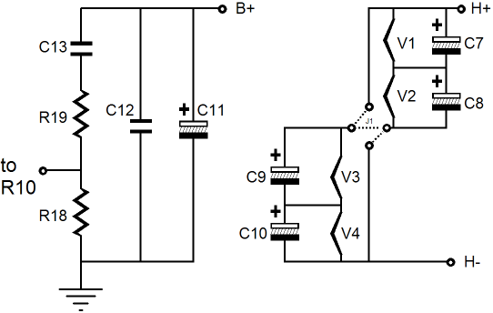
The Aikido magic requires sampling the power-supply noise and delivering a suitable percentage of the noise to the bottom triode’s grid. The bottom, leftmost circuit shows this noise voltage divider and the power supply capacitors.
The four tubes present their heaters in series to the B+ voltage, as shown in the rightmost circuit above. Jumper 1 connects all the heaters in series. The two additional diagonal dotted lines show a secondary possible arrangement, wherein the heaters can be arranged in series/parallel, so that 12V heater power supply can be used with 6V heaters. Why? One thought I had when designing this new board is that it would useful not to paint myself into a 6GM8 corner. In other words, what if someone wanted to use 6CG7 or 6DJ8s instead. Since the heater string holds its own connection pads on this board, the 24V B+ can be exceeded, as the tube heaters will still see their required voltage under this arrangement. For example, with a 12V heater power supply, a B+ voltage of 170V could be used with 6922s. if you think that you see a fatal flaw with this plan, you are right. The solid-state voltage regulators are not high-voltage devices. The IXCY10M45S, on the other hand, is a high-voltage device. Thus the bottom regulator can be replaced with a IXCY10M45S and the top regulator, any high-voltage, low-wattage, N-channel MOSFET that can be had in the TO-220 package. In this scenario, the big limitation is the four heatsinks, as they are only worth about 5W of dissipation each. So a B+ voltage of +170V would impose a current limit following about 50mA though each solid-state buffer stage. Now, 50mA will drive 300-ohm headphones, like the HD-650s to ear-deafening levels and it will drive yards and yards of high-capacitance interconnect, but it will only put out about twice the power that an iPod would into a 32-ohm load.
When Will the Boards Be Available? By the way, I tried using 6DJ8s in place of the 6GM8s at 24V. It works, but the distortion is higher. (Now, what just might work is a 48V power supply and four 12BH7s or ECC99s; still, only 24V from cathode to plate is not all that much better than 12V.) All tubes can be run at low plate voltages, but they do not work well there, as the electrons find it hard to stick to the plate at low voltages. The 12SX7, like the 6GM8, was specially designed to work with a low plate voltage. Maybe, if there is enough demand, New Sensor can be convinced to restart the production lines on the 6N27P again. If you know Mike Matthews, give him a nudge.
Next Time
//JRB *Most of the audio industry is filled with self reviews, which probably helps explain why it continues to decline each year.
|
Only $12.95 Download or CD ROM www.glass-ware.com
|
|||
| www.tubecad.com Copyright © 1999-2008 GlassWare All Rights Reserved |
