| John Broskie's Guide to Tube Circuit Analysis & Design |
19 May 2008
More GainClone Thoughts
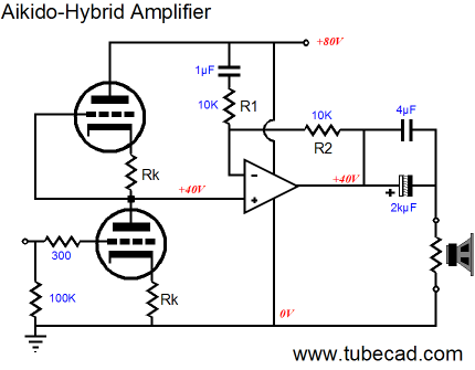
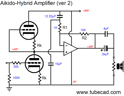
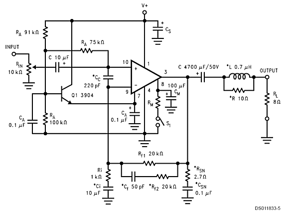
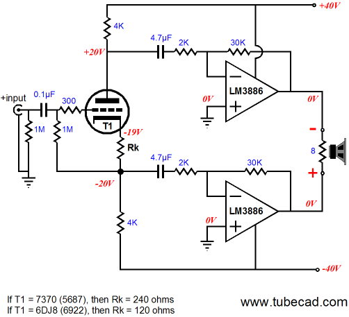
Aikido-Gain-Cone Power Amplifier Gain = mu The tube input stage realizes a gain equal to half the mu (amplification factor) of the triodes used. Thus, for example, a 6SN7, with a mu of 20, will deliver a gain of 10, or +20dB, as 20Log(Gain) gives us the gain in decibels. The solid-state power amplifier develops a gain of 2 (+6dB), as the two 10k feedback resistors result in a gain equal to R2/R1 +1. Now a gain of 2 against half a mu equals mu. So, for example, a 6DJ8, with a mu of 33, will deliver a final gain of 33 at the speaker terminals. Finally, we get to the odd termination of the 1µF capacitor at the B+ and not at ground, as is the usual setup in 99.99999% of amplifier circuits. What is this all about?
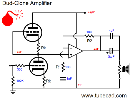
Had the solid-state power amplifier's feedback resistor been terminated into ground, as shown above, the amplifier would have developed the same amount of gain, but the PSRR would have been much, much worse, as it would approach zero, as all the power-supply noise would appear at the output. Here is why: the two triodes effectively define a two-resistor voltage divider, so half of the power-supply noise is presented to the solid-state power amplifier at its positive input; then, the solid-state amplifier's gain of 2 doubles the input noise to unity. On the other hand, terminating into the B+, means that the power amplifier's negative input connects to the B+ noise, which the amplifier will invert at its output. In other words, the power amplifier is configured as both an inverting amplifier with a gain of 1 and as a non-inverting amplifier with a gain of 2. Thus, 0.5 x 2 + -1 x 1 = 0, which equals an infinite PSRR figure.
The above schematic shows the DC voltage relationships within this hybrid amplifier; the schematic below shows the noise relationships.
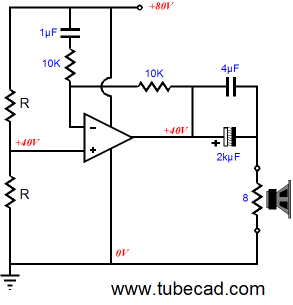
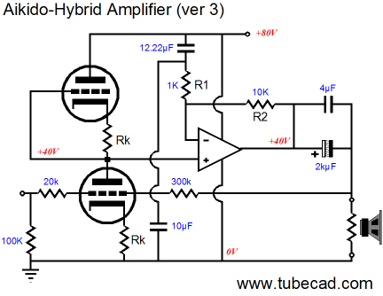
In theory, a complete cancellation of power-supply noise is possible, but with real tubes and 1% resistors, we should be able to get something close to -60dB or better. The big problem is that the readily available, cheap, and good-sounding National Semiconductor Overture™ series power amplifiers cannot be run anywhere near a gain of just 2, requiring a minimum gain closer to 10. The workaround is to run the Overture™ power amplifiers with a high gain and at the same time lower the amount of B+ noise that is injected into the inverting input, as shown below.
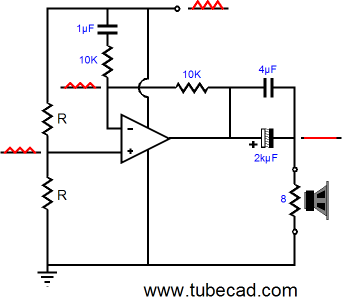
Two problems are likely to arise, however. The first is that the final gain is likely to be huge, as the tube input stage is not likely to yield anything less +20db (might be as high as +34dB with a 12AX7) and the solid-state power amplifier will add its +20dB. The second possible problem is getting the right ratio of power-supply noise, as capacitors, particularly electrolytic capacitors, are not tight tolerance components. The solution to both problems might be to use a feedback loop that encompasses the entire hybrid amplifier, as shown below.
What I like about the above circuit is that the tube is charge of the solid-state power amplifier.
Further PSRR Enhancements
(I have seen the schematics of some high-end Sony gear that employed asymmetrical power supply reservoir capacitor values; in other words, a much greater amount of capacitance was placed in the negative half of the power supply than the positive half, no doubt in an attempt to overcome the imbalance in PSRR between the power supply connections.) If a bipolar power supply had been used, the same noise-reducing trick of terminating into the B+ could be used, but the weak PSRR performance from the negative-PS connection would override the better PSRR from the positive connection. No doubt the coupling capacitors at the output are also causing some distress for some. Aren't all coupling capacitors bad? Yes, in fact they all are, but then so are all power supply capacitors. At least these coupling capacitors are so obviously in the signal that no one can ignore them. Moreover, coupling capacitors will protect the loudspeakers (and to a large extent, the power amplifier itself). By the way, I used to be vehemently opposed to capacitor-coupled power amplifiers, in spite of having heard several good-sounding capacitor-coupled amplifiers. So I know how strong an attachment to a philosophical view can be. I must point out that not all National Semiconductor Overture™ series (Gain-Clone type) power amplifiers are easy to use with a mono-polar power supply. The famous LM3875 amplifier can be used much more readily than the LM3886, because the LM3875 does not hold a ground pin that the LM3886 does.
The LM3886's ground pin must attach to the power supply midpoint, which may or may not be the actual ground used. And this voltage midpoint must offer a low impedance, as it will be used to reference the idle-current circuitry within the LM3886; thus, the use of the 2N3904 transistor in the above schematic.
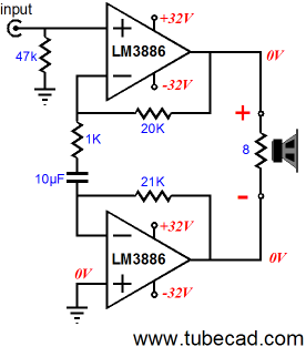
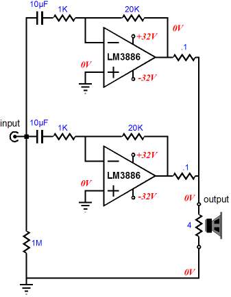
Differential GainClones Usually, we don't get the full 200W. Why not? When an 8-ohm load is attached to the differential amplifier, each amplifier effectively sees a 4-ohm load, not an 8-ohm load. So the differential can only deliver twice what it puts out into a 4-ohm load. For example, a nominally 50W power amplifier might be able to put out 75W into 4 ohms, so two of these amplifiers run differentially would develop 150W into an 8-ohm load, twice the 4-ohm output. Of course, if the 50W amplifier can deliver 100W into 4 ohms, then two in a differential arrangement would yield 200W into 8 ohms. Now the question is "Since the differential amplifier presents a balanced output, does it also require a balanced input?" Certainly, a balanced input signal would make life easy for us, as the following circuit could be thrown together.
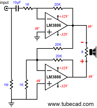
On the other hand, if only unbalanced input sources are available, the following two schematics might prove ideal.
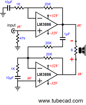
(By the way, the key word in the last sentence was “might.” I have not actually tested the above two circuits. I hope that you noticed the striped-down schematics, showing only the essential parts, leaving off the Zorbel networks and compensation capacitors.) The first circuit offers a high input impedance and only uses one large-valued capacitor. In contrast, the second circuit presents a low input impedance of 1k and may develop too high a DC offset. Trying to fix this circuit may result in something like the following, which requires three big capacitors and is less desirable because of them.
What would I do? I would go the hybrid route in a flash. If it doesn't glow, it doesn't go...
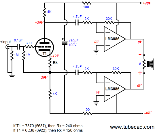
The above hybrid amplifier uses a triode in a split-load phase splitter to create a balanced input signal for the balanced power amplifier that follows it. We can expect a little loss from the tube frontend, but it little matters, as the solid-state power amplifiers effectively double tube stage's gain. Thus, the final gain in the above amplifier would be about +29dB, which is close to perfect. In other words, only a little over 1Vpk of input signal would bring this amplifier to full output. The split-load phase splitter is designed to null power-supply noise at its two outputs, but a little extra help might be needed, which is what the additional two resistors and 470µF capacitor provide.
By the way, the 7370 is an interesting dual triode; it is a 5687 with a 40V heater element, which means that it could be used with the existing bipolar power supply. (I would place two resistors in series with the heater to both drop the voltage to 40V across the heater and to reference the heater to a voltage slightly higher than -19V.) But a 6DJ8/6922 dual triode could be used instead, with a 6.3V power supply.
What JRB Would Really Do On the other hand, if we are willing to splurge and add more parallel power amplifiers, then we should be able to get away with just large heatsinks. For example, even if I just wanted to drive 4-ohm loudspeakers (in a non-differential fashion), I would use two parallel power OpAmps, as each amplifier would effectively see an 8-ohm load. Yes, two LM3886s are not as cheap as one LM3886, but 40 LM3886s are cheap compared to one NOS RCA 845. Coming as we do from the world of $800 tubes $300 coupling capacitors gives us a different perspective on what is expensive compared to our solid-state-loving brethren. How do you hook up parallel power amplifiers? There are several ways to do it, but the following is a proven approach.
The 0.1-ohm resistors at the each amplifier output prevent the amplifiers from fighting each other and the two 10µF coupling capacitors allow each amplifier to minimize its DC offset. In this circuit, tight-tolerance (say, 0.1%) feedback resistors are a very good idea. Remember, we want the two amplifiers to drive the speaker, not fight each other. And be sure to read National's PDF on parallel amplifiers. By the way, if you are wondering why the amplifiers are configured in the inverting mode, not the usual non-inverting mode, the answer is that at least one less capacitor is needed (the common input capacitor) and that the amplifiers perform better in the inverting mode. Here is what LM4780's data sheet says:
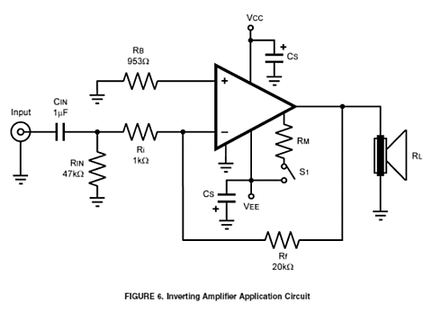
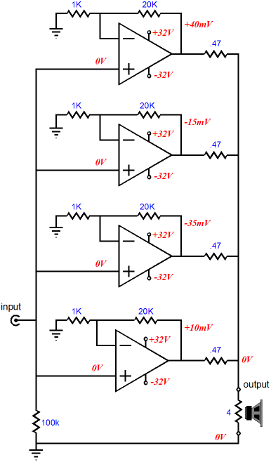
By the way, I am a huge advocate of RFM (Read the F***ing Manual) and I would never use an OpAmp without first carefully reading the OpAmp's data sheet. Amazingly enough, I am almost alone in observing this practice, as I get asked for help from friends with OpAmp-based projects and they never read the data sheet, believing that some posting on a DIY forum is all that is needed. Having said that, I must admit that I don't get the above schematic. Why is resistor Rin (47k) positioned after the coupling capacitor, instead of before it? And why is resistor Rb equal to Ri and Rf in parallel, when Ri is not DC coupled to the input? In other words, I believe that Rb should equal Rf, as that would result in the lowest DC offset. And isn't Cin's value ten times too low? (Maybe National should have had Bob Pease proofread the data sheet.) Speaking of DC offset, the entire line of National Semiconductor's Overture™ series of OpAmp power amplifiers all offer a low input DC offset, usually only 1mV, which against a DC gain of 30, only equals 30mV at the loudspeaker terminal. Not much to worry about. Now imagine a bell curve of input DC offsets, with most data points falling on 0V and only a few at -5mV and +5mV. Now, if four LM3886s were placed in parallel, the resulting DC offset would equal the sum of all four DC offsets. In the schematic below, rather idealistically, that sum becomes 0V.
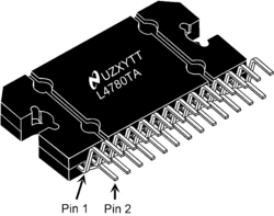
Note that no capacitors appear in the circuit, which is a godsend, as any failing the feedback resistor terminating capacitor presents will be amplified by the gain of the amplifier. (Probably, half of the poor sound from many solid-state power amplifiers can be traced back to the electrolytic capacitor in the feedback loop.) Also note that the assumption made is that the signal source is DC offset free. It may not be. Thus, a safer approach would be to add a single input coupling capacitor, as any input DC voltage will be amplified by the amplifier's gain of 21. While you are at it, note that each power OpAmp effectively sees a 16-ohm load, although 4-ohm loudspeakers are being driven. Also note the large series buffer resistors (0.47 ohms); these resistors are effectively in parallel, so the actual series resistance the loudspeaker sees is closer to 0.12 ohms, which still deliver a damping factor of over 50. If eight power OpAmps were placed in parallel, then 1-ohm resistors could be used instead of 0.47 resistors, which would still offer the same damping factor. Why not use 0.1-ohm resistors no matter how many amplifiers are in parallel? First, I do not believe high damping factors buy you anything important; second, the larger-valued resistors greatly help ensure equal current sharing and ease DC offset concerns. Should multiple Zorbel networks be used? I have seen each amplifier get its own Zorbel network in several schematics, but I bet that one for each bank of parallel amplifiers would be sufficient. By the way, National Semiconductor makes stereo power OpAmps, the LM4780 for example. This is a recent design, which if I remember correctly, offers lower distortion and DC offset than the older power OpAmps. This might the best chip to use in a parallel configuration; in other words, instead of four LM3886s, use two LM4780s.
Next Time
//JRB
|
E-mail from GlassWare Customers And
High-quality, double-sided, extra thick, 2-oz traces, plated-through holes, dual sets of resistor pads and pads for two coupling capacitors. Stereo and mono, octal and 9-pin printed circuit boards available.
Designed by John Broskie & Made in USA Aikido PCBs for as little as $24 http://glass-ware.stores.yahoo.net/
Now accepting Support the Tube CAD Journal & get an extremely powerful push-pull tube-amplifier simulator for TCJ Push-Pull Calculator
TCJ PPC Version 2 Improvements Rebuilt simulation engine *User definable
Download or CD ROM For more information, please visit our Web site : To purchase, please visit our Yahoo Store:
|
|||


| www.tubecad.com Copyright © 1999-2008 GlassWare All Rights Reserved |