| John Broskie's Guide to Tube Circuit Analysis & Design |
07 Sept 2008
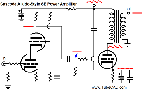
Hybrid SE CF Power Amplifier Let me start at the beginning: about two months ago, a TCJer sent me an extremely interesting e-mail that contained a description of his new hybrid, single-ended, cathode follower amplifier that used OpAmps as a frontend and an EL34 as the single output device, configured as a cathode follower with the output transformer’s primary as its load. His circuit was complex and ingenious; but I thought it a bit too complex and feared that it gave too much control of the signal to the solid-state portion of the circuit. Before replying to his e-mail, I thought I would draw some alternative circuits that would be more in line with my own audio philosophy. Well, it took much longer to finnish drawing the schematics—about a week—than I thought it would. Then when I went looking for his e-mail, I could not find it. I know that many are thinking, "How hard can it be to find one e-mail message?" but they probably do not get as much e-mail as I do. (This website regularly receives over 1,000,000 hits a month, which in turn prompts a lot of e-mail.) As I scanned through each of the hundred e-mails from the week prior, I could not find it. Somehow I had deleted his e-mail by accident and it was gone forever. As I wasn't hurting for blog topics, this sad story would have ended there (unless the TCJer sent a follow-up message, which he didn't). But my last blog entry, which covered the Ultrapath circuit, made me change my mind. One of the circuits I had come up with shared a similar power-supply noise canceling technique to my Aikido-like, two-capacitor, single-ended amplifier, SE-noise-reduction circuit from 1999, as shown below .
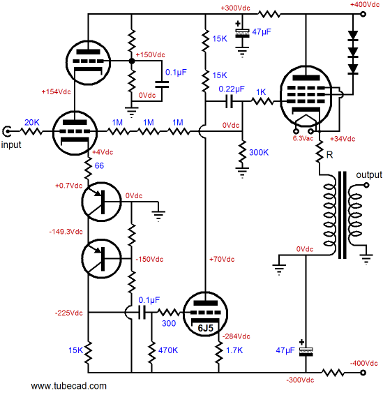
In the above schematic, we see how injecting a small portion of the power-supply noise into the output tube’s cathode can lower the power-supply noise at the loudspeaker. (See blog number 147 for more details.) See if you can spot when this capacitor-based voltage divider makes its second appearance. Cathode follower output stages were covered back in 2005. The nutshell-fitting conclusion was that the cathode follower output stage, because of its low gain, which is always less than unity, must make enormous demands on its input and driver stage supply a voltage swing even greater than what the cathode must swing. In other words, although the cathode follower output stage offers low distortion, the input and driver stages are so greatly burdened that their combined distortion contribution can easily undo the gains made by the cathode follower output stage. The following hybrid amplifier uses a cascoded input stage develop a high amount of wide-bandwidth gain to drive the second gain stage to full output. Two PNP transistors are used to increase the solid-state device's survival odds and to halve each transistor’s heat dissipation. The two triodes also work to halve each triode’s dissipation and to increase the input stage’s PSRR. This inverted cascode circuit does not invert the input signal’s phase at the bottom transistor’s collector’s connection to the 15k load resistor. And because the collector exhibits such high impedance, virtually no PSRR obtains at the cascode’s output. This is just what we want, as we want the 6J5’s grid to see all of the negative power supply rail’s noise, so that the all the power-supply noise is nulled at the 6J5’s plate. To better understand how the power-supply noise can be nulled, imagine that the entire input stage were clipped from the circuit, leaving only the 6J5 (with its grid “grounded” to the negative power supply rail) and the output stage. Because the positive and negative power supply rails track each other, differing only in the 180-degree phase shift, much of the rail’s power-supply noise will cancel at the 6J5’s plate, as the two 15k plate resistors come close to matching the 6J5’s plate impedance. The noise cancellation is not perfect in this example, because this amplifier was designed for maximum power output, not lowest noise.
In addition to this circuit’s intrinsic power-supply noise rejection, a negative feedback loop works to realize a steady fixed gain and low noise and low distortion. Unfortunately, the series input feedback-setting 20k resistor presents too heavy a load for many tube-based music sources and the three 1M feedback resistors’ high resistance makes any stray capacitance more injurious. The workaround is to reconfigure the feedback loop, so the amplifier returns to a high input impedance and feedback resistors are reduced to much lower values. This change in feedback arrangement requires that the driver stage not invert the input stage’s output signal phase, which requires configuring the driver stage as a grounded-grid amplifier, not a grounded-cathode amplifier. In the following circuit, a tube-based-current-feedback OpAmp, we see the driver stage’s grid “grounded” at the negative power supply rail and its cathode directly attaching to the cascode’s output. In other words, we have eliminated one coupling capacitor from the signal path and removed one source of phase shift from the feedback loop—a win-win situation.
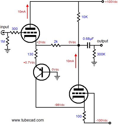
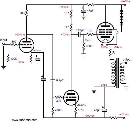
Applying the same reconfiguration to our power amplifier is easy enough.
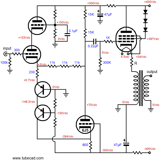
Note the use of three feedback resistors in series. Why? The driver stage must swing a huge output signal to drive the cathode follower's output stage and resistors can suffer from a voltage-induced distortion, which the three feedback resistors reduces by a third. Finally, we arrive where I should have begun, if I wanted to hold on to as many readers as I could, as not doubt all those hybrid circuits turned off many pure-tube diehards. The following circuit uses two coupling capacitors and a variation on the Aikido-like two-capacitor voltage divider technique. This time, however, we want to project negative-rail power-supply noise into the input triode’s plate, not null the power-supply noise, as the nulling will occur at the driver stage’s output. Note that no feedback loop is used, as there is not enough gain to drive a feedback loop nor is there a ready feedback input, as the input tube’s cathode is already being used by the two-capacitor voltage divider.
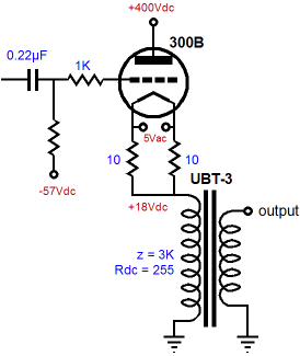
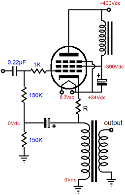
A few words about the output tube. The output tube used in the preceding schematics was a triode-connected pentode. Why? The EL34 and KT88 are both readily available and relatively cheap; in addition, they are both easy t drive to full output. The three diodes that span from the B+ connection to the pentode’s screen can be replaced by a zener or a resistor or even a piece of wire, although the resistor is the safest choice, as only it limits current conduction. Nonetheless, the lower impedance presented by the solid-state diodes sounds better. Wait a minute—what if you like only real triodes or only DHT tubes? Not a big deal, just try the following configuration instead.
By the way, no matter what type of output tube is used, each channel’s output tube must use its own floating heater winding (or DC power supply), which must be referenced to the output tube’s cathode. Before altogether leaving the pentode behind, I should point out that the pentode output tube can be used as pentode, as the following circuit shows.
Next Time
//JRB
|
And
High-quality, double-sided, extra thick, 2-oz traces, plated-through holes, dual sets of resistor pads and pads for two coupling capacitors. Stereo and mono, octal and 9-pin printed circuit boards available.
Designed by John Broskie & Made in USA Aikido PCBs for as little as $24 http://glass-ware.stores.yahoo.net/
The Tube CAD Journal's first companion program, TCJ Filter Design lets you design a filter or crossover (passive, OpAmp or tube) without having to check out thick textbooks from the library and without having to breakout the scientific calculator. This program's goal is to provide a quick and easy display not only of the frequency response, but also of the resistor and capacitor values for a passive and active filters and crossovers. TCJ Filter Design is easy to use, but not lightweight, holding over 60 different filter topologies and up to four filter alignments: While the program’s main concern is active filters, solid-state and tube, it also does passive filters. In fact, it can be used to calculate passive crossovers for use with speakers by entering 8 ohms as the terminating resistance. Click on the image below to see the full screen capture.
Tube crossovers are a major part of this program; both buffered and un-buffered tube based filters along with mono-polar and bipolar power supply topologies are covered. Available on a CD-ROM and a downloadable version (4 Megabytes). Download or CD ROM
|
|||


| www.tubecad.com Copyright © 1999-2008 GlassWare All Rights Reserved |