| John Broskie's Guide to Tube Circuit Analysis & Design |
Post 246 08 October 2012
Inverted Current Mirror
Perhaps, a better name for this circuit would have been "current matcher" or "current equalizer," as "mirror" implies mirror image, "an image that has its parts arranged with a reversal of right and left, as it would appear if seen in a mirror," as the American Heritage Dictionary informs us. Well, what could we do with an inverted current mirror, one that didn't match current, but inverted the delta, the change, in current conduction.
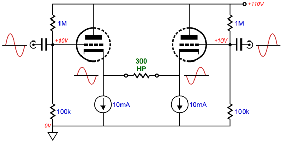
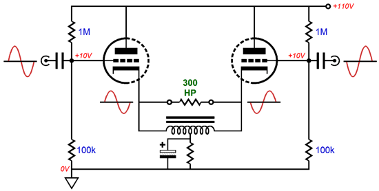
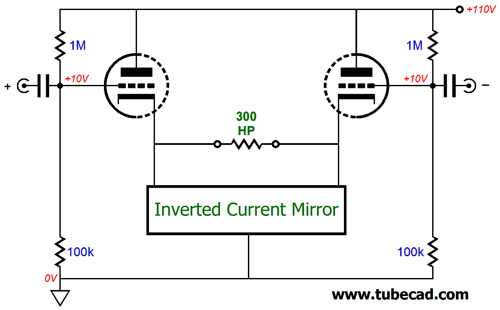
Instead of two cathode resistors, two constant-current sources are used. The load attaches in between the two cathodes. No coupling capacitors are used, because the no DC differential voltage exists between the cathodes—well at least in this theoretical example. A balanced input signal is used and the headphone driver sees the net delta in current conduction between the two triodes minus the idle current through the contstant current sources. Simple enough. The two constant-current sources could be created out of OpAmps and transistors or, even, tubes, but the easiest means is by using an antique and technologically simple device: the center-tapped inductor.
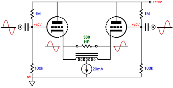
Or, we can replace the resistor at the center tap with a constant current source.
The question is: given optimal plate voltage and triode type, what is the maximum peak voltage that this circuit can develop across this external load impedance of 300 ohms? The answer is 10mA against 300 ohms, or 3Vpk-pk. Why? The constant-current sources (or the center-tapped inductor, which act as constant-current sources) set the limit. For example, if the right triode is driven to cutoff, so it ceases to conduct altogether, the right-bottom constant-current source will deliver its 10mA of current into the 300-ohm load, which will then travel up the left triode's cathode and then through its plate into the B+ connection. Effectively, the left triode's cathode will be loaded by both constant-current sources in parallel, so its maximum current conduction can never be more than 20mA. Well, if the left triode is conducting 20mA, why doesn't the 300-ohm load resistance see 6Vpk-pk across it? The load is in series with the right constant-current source, so it can only see a maximum of 10mA. Conversely, if this constant-current source could be compelled to conduct twice its idle current and the left constant-current source forced to cease its current conduction, then the 300-ohm load resistance would experience a 6V voltage drop, as 20mA would flow through it. Such an arrangement requires an inverted current mirror.
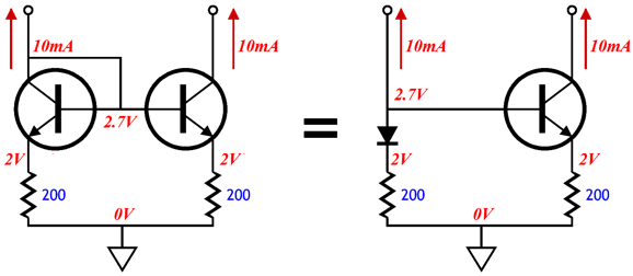
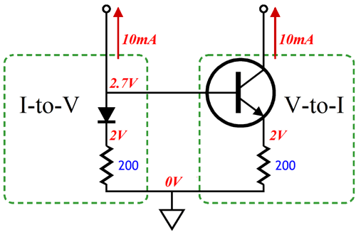
Like a constant-current source, an inverted current mirror could be created out of OpAmps and transistors or even tubes. But before moving on to a design example, let's pause and look into what a current mirror really is: a I-to-V converter that cascades into a V-to-I converter.
A resistor is a current-to-voltage converter, its conversion ratio being set by its resistance. The NPN transistor and emitter resistor define a voltage-to-current converter, its conversion ratio being set by its emitter resistor's resistance. This is why we specify the same resistor value for both resistors. Now, what we need is an inverted voltage-to-current converter. Once again OpAmps and transistors could be used, but let's start with a tube version.
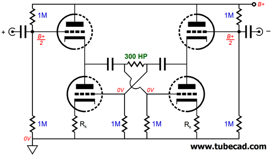
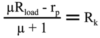
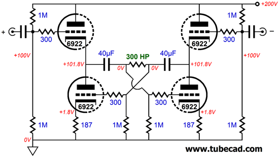
This is very much a fully push-pull circuit. A balanced input signal is required and the load impedance sees differential currents and voltages developed. The top-left and bottom-right triodes conduct in unison, as do the top-right and bottom-left triodes. So, when the top-left triode sees a positive input signal, it increases its conduction, as does the bottom-right triode, while the top-right and bottom-left triodes decrease in conduction, as they see a negative input signal. We know where the top triodes get their input signal, but where do the bottom triodes find their balanced input signal? The voltage develop across the load creates the needed inverted balanced input signal for the bottom triodes. Those who expect me to now proclaim the need for balanced current conduction will not be disappointed. Ideally, we want all four triodes to work equally, so the maximum possible voltage swing across the external load impedance can be realized. As you might expect, this requires that the optimal cathode resistor values be determined, which in turn requires some fancy mathematical analysis. The result of which is the following formula:
The µ refers to the bottom triodes' amplification factor (mu), not the top triodes'. Interestingly enough, the formula doesn't know that the top triodes exist; they could be replaced by pentodes or N-channel MOSFETs or even transistors and the formula would still work. In other words, this circuit is not limited to 6922/6DJ8 tubes, as 6H30 or 5687 or ECC99 or even 300B tubes would work. It’s not the tubes, it’s the topology… Let's now fill in the above circuit with actual values.
If you are still not getting how this topology works, one way of thinking about this circuit is to see it as being an upside-down, differential, White cathode follower or something like an SRPP. And just like these push-pull circuits on the cheap, this topology is load dependent, as the it is the load impedance that creates the required anti-phase balanced signal. In other words, 2k and 32 ohm loads are not going to prompt the same performance, because the circuit is optimized for 300-ohm loads. If you wish to drive 32-ohm headphones, such as the famous Grado line, then an output transformer with a 3:1 winding ratio will be needed.
A 3:1 winding ratio implies a 9:1 impedance ratio, so the 32-ohm headphone driver will be reflected as a 288-ohm load. Okay, we move on, with a hybrid version.
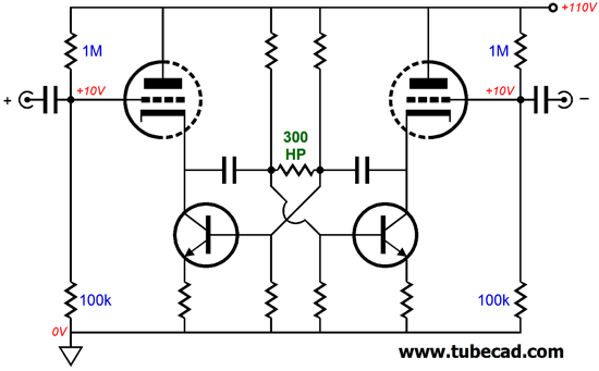
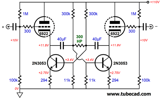
First of all, note the lower B+ voltage of only 110Vdc. The transistors need just enough voltage headroom to allow the desired maximum voltage swings into the load. Also note how, at idle, the transistors and their emitter resistors function as constant-current sources. But in the presence of an audio signal, the transistors function as inverted current mirrors. Here is the same circuit but fleshed out:
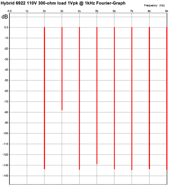
Unlike the all-tube version, the transistors cannot self bias through their emitter resistors, so a pair of two-resistor voltage dividers is needed. The headphone driver sees 3.4Vdc on each side, but differentially it sees 0Vdc at idle. The emitter resistors are selected to roughly match the load impedance, as the transistors offer much lower output impedance at their emitters than triodes do at their cathodes. By adding a -12Vdc power-supply rail and two DC servos, we can get the cathodes down to ground level at idle, which would allow attaching the load directly across the two cathodes, bypassing the need for coupling capacitors for the headphones (although smaller-valued coupling capacitors would still be needed for the transistors). Still, I like the peace of mind that comes from having my expensive headphones protected from possible damage to arcing or jiggled tubes. The output impedance is about 270 ohms, not the less than 200 ohms you might expect. The distortion harmonic structure is pure push-pull.
At full output 6Vpk, which is plenty loud, the distortion climbs 1%. Could a Circlotronesque power amplifer be built based on this design and many mighty power triodes, such as the 6AS7 or 6C33? Indeed, but do not expect more wattage, as this amplifier is still current-limited by the triodes. Could an inverted current mirror be located at the plates, rather than at the cathodes? Yes, if PNP transistors are used.
PP Current Mirror HP Amplifier
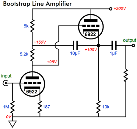
If it were not for the 10µF capacitor, this circuit would look like a CCDA design. That capacitor, however, makes a huge difference. It effectively makes the 5.2k plate resistor appear much, much larger in value, almost approaching a constant-current source in impedance. It also increases the cathode follower's output impedance. Think about it: if a positive pulse is forced on the output, the 10µF capacitor will relay that pulse to the top of the 5.2k resistor, which will then relay the pulse to the cathode follower's grid, reduced by the voltage division between the 5.2k resistor and the impedance presented by rp + (µ + 1)Rk. In addition, the 10µF capacitor improves the PSRR over the CCDA circuit. This circuit is not very well known, I have to admit. About ten years ago I had a big exchange between several high-power readers about this circuit. I meant to publish the exchange long ago, but I after a month of furious e-mail exchanges, I felt that the circuit had been beaten to death. Today is a good time to revive the debate. My take was that this circuit is not a single-ended topology, but a push-pull affair—in fact, my view is that this topology is an SRPP in disguise. WHAT!? As I look at it, I see SRPP being dragged down by two extra resistors. As I see it, both triodes work into the external load, the input triode via the 10µF capacitor and the "output" tube directly at its cathode. Don't see it? Let's short out the 10µF capacitor and make resistor R only 200 ohms, which will then look like the following circuit.
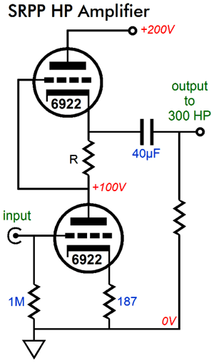
As the input triode on the left conducts more, its plate voltage is pulled down, increasing the voltage drop across resistor R, forcing the cathode follower's grid to be even more negative than its cathode, thereby decreasing its conduction. Push-pull operation in other words. So, how essential are the two 10k resistors to the this circuit's functioning? Not very is my answer, which we can see by removing them. Without the needless 10k resistors, we see the naked SRPP topology.
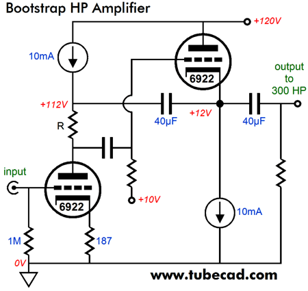
I know that some readers are are thinking: Finally, thank God, Broskie comes to his senses and realizes that the SRPP is the absolutely best tube circuit possible and that all other tube circuits are just distractions. Sorry, but no. In fact, I am now going to work backwards and return to the bootstrap topology, but with an important difference: constant-current sources and a lower B+ voltage.
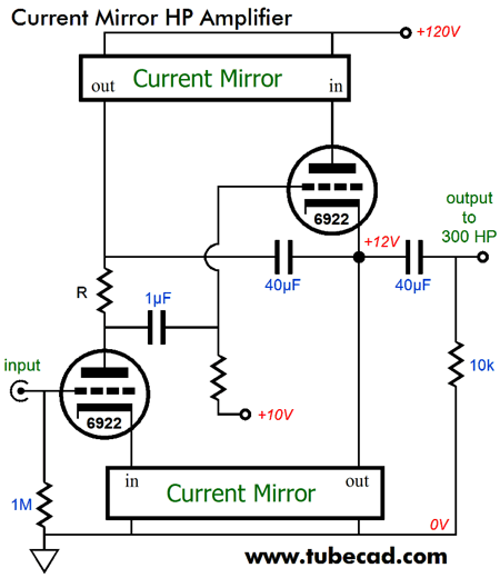
The two constant-current sources and the coupling capacitor between stages allow us to get away with a lower B+ voltage, which would have been impossible with the SRPP topology. If resistor R's value is carefully chosen, R = (2Rload + rp)/µ then the two tubes will work equally at driving the 300-ohm load. The maximum voltage swing into the 300-ohm load is 6Vpk, as the two constant-current sources cancel each other out and the two triodes operate in class-A, push-pull fashion, so twice idle current through one triode is the peak current swing into the load. The constant-current sources will dissipate heat, so do not believe that we are getting something for nothing here. Now, what would happen if we replaced the constant-current sources with two plain-Jane current mirrors?
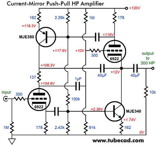
We retain the low B+ voltage and the circuit dissipates the same amount of heat at idle, but we theoretically quadruple the power we can deliver into the same load impedance, as we can now swing twice the current into the load. To see how that is possible, imagine that input triode is driven to cutoff by a negative-going input signal. The bottom current mirror must also cease conducting, leaving both the top triode and current mirror to pull up unhindered. If the top triode reaches 20mA of conduction, so, too, will the top current mirror, delivering 40mA peak into the 300-ohm load. Okay, take a deep breath before examining the following schematic. It isn't as complicated as it might appear at first glance.
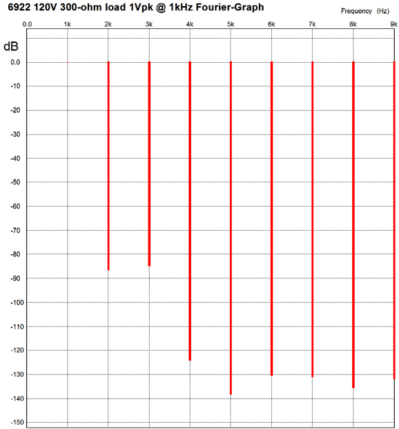
The current mirrors do not need voltage-dropping diodes, as they are capacitor coupled to their current-sense resistors. And do not be troubled by the 178-ohm and 162-ohm current mirror resistor mismatch, as the top 178-ohm resistor is in AC parallel with the 2.26k resistor at the top and the bottom 178-ohm resistor is in AC parallel with the 2.43k resistor at the bottom. The voltage gain is close to 4 (+12dB) and the PSRR comes in at about -16dB. The output impedance is almost 800 ohms. In SPICE simulations, the distortion is low, as the following graph shows.
Not bad, a blend of SE and PP harmonic structure. Expressed as THD, the distortion is below 0.01%. In order to get the full potential 12Vpk would require my tweaking the B+ voltage and part values, which I am not up to right now, so I will show the 6Vpk graph instead.
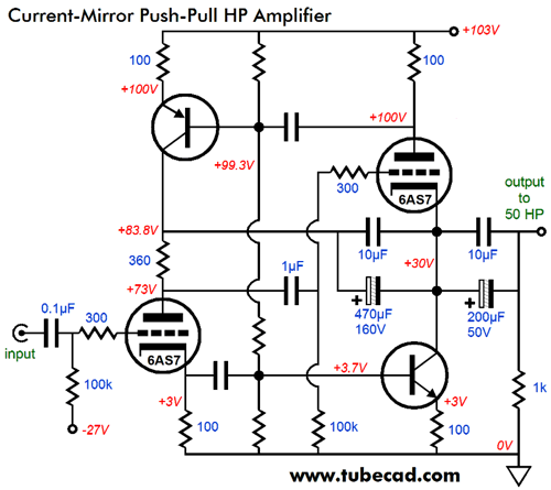
Once again, not bad, well below 1%. To be honest, I didn't envisage 12Vpk voltage swings when I created the SPICE circuit, so I didn't give the output room to swing that big a value. Nonetheless, an interesting circuit. Well, could a Circlotronesque power amplifer be built based on this design and many mighty power triodes, such as the 6AS7 or 6C33? Indeed. As the parallel current mirrors double the peak current swing into the loudspeaker, the power would increase by fourfold. But before we break out the champagne, do not forget that this amplifier is restricted to true class-A, push-pull operationl. A better use might be a headphone amplifier powerful enough the new planer 50-ohm headphones, which require big voltage swings. A negative power-supply rail will be needed.
As I look at it now, I see that coupling capacitors between the first stage and the load can terminate at the load, rather than at the top triode's cathode.
Next Time
//JRB |
I know that some readers wish to avoid Patreon, so here is a PayPal button instead. Thanks.
John Broskie
And
High-quality, double-sided, extra thick, 2-oz traces, plated-through holes, dual sets of resistor pads and pads for two coupling capacitors. Stereo and mono, octal and 9-pin printed circuit boards available.
Designed by John Broskie & Made in USA Aikido PCBs for as little as $24 http://glass-ware.stores.yahoo.net/
The Tube CAD Journal's first companion program, TCJ Filter Design lets you design a filter or crossover (passive, OpAmp or tube) without having to check out thick textbooks from the library and without having to breakout the scientific calculator. This program's goal is to provide a quick and easy display not only of the frequency response, but also of the resistor and capacitor values for a passive and active filters and crossovers. TCJ Filter Design is easy to use, but not lightweight, holding over 60 different filter topologies and up to four filter alignments: While the program's main concern is active filters, solid-state and tube, it also does passive filters. In fact, it can be used to calculate passive crossovers for use with speakers by entering 8 ohms as the terminating resistance. Click on the image below to see the full screen capture.
Tube crossovers are a major part of this program; both buffered and un-buffered tube based filters along with mono-polar and bipolar power supply topologies are covered. Available on a CD-ROM and a downloadable version (4 Megabytes). |
|||


| www.tubecad.com Copyright © 1999-2012 GlassWare All Rights Reserved |