| John Broskie's Guide to Tube Circuit Analysis & Design |
17 August 2013 PS-17
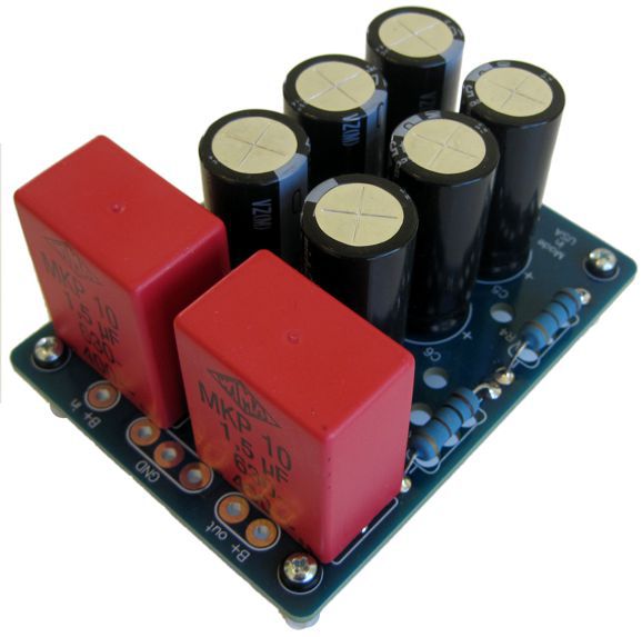
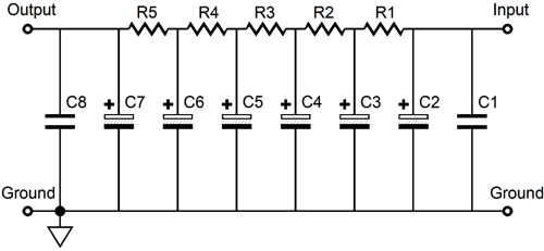
The PS-17 is a new power-supply RC filter. It is not a complete power supply, as it requires an external power supply to establish the B+ voltage. In other words, it is an add-on for an existing power supply. It could, however, be used with a GlassWare Rectifier-1, which would create complete high-voltage power supply. This PCB uses five cascading RC filters to provide suitably well-filtered B+ voltage for class-A tube circuits. Each RC filter consists of a 47µF/450V (or 220µF/200V) capacitor and a 3W power resistor. The input and last RC filter are bypassed by a high-quality Wima 1.5µF/630V polypropylene film capacitor (MKP-10).
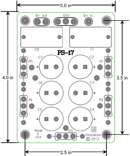
At the input, an extra electrolytic capacitor used, so a total of six electrolytic capacitors sit on the board. The PCB is quite compact at 3 inches by 4 inches (75mm by 100mm).
The circuit is quite simple: raw DC voltage is applied and one end and much cleaner DC leaves at the other end. The assumption behind the circuit is that it will be used with a class-A tube circuit, not a class-AB power amplifier. I have received many e-mails asking which is better a single RC filter with lots of capacitance or many RC filters with a little capacitance in each RC stage. The answer is that it depends on the powered load. If the load is a class-AB or class-B power amplifier, then the single RC filter is the best choice, as it will offer the lowest output impedance, due to the large amount of capacitance. On the other hand, if the load draws a steady average current draw, which most tube circuits do, then the cascading RC filters are better, as they better filter away harsh rectifier-induced harmonics.
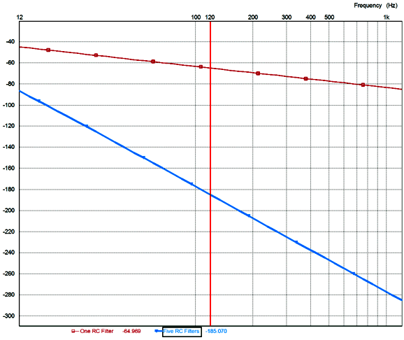
The above graph shows the attenuation versus frequency for the two types of filters. The red plot is based a single RC filter that holds a single 10k resistor and and a 235µF capacitor. At 120Hz, the attenuation is -65dB and its output impedance is about 7 ohms. The blue plot is based a five cascading RC filters each holding a single 2k resistor and and a 47 µF capacitor. At 120Hz, its attenuation is -185dB and its output impedance is about 33 ohms. In other words, both filters hold the same amount of resistance and capacitance; it's just that they are differently distributed. The difference in attenuation is far more extreme than 120dB difference might seem to imply, as a 120dB reduction in ripple amplitude equals a 1,000,000 times reduction. For example, if 1mV of ripple made it past the single RC filter, then only one 1µV would leak past the the five RC filters. The single RC filter results in classic -20dB per decade of higher frequency, whereas the five cascading RC filters deliver -100dB of attenuation per decade of higher frequency. Of course, the capacitor's own internal series inductance will impose their own limit high-frequency attenuation. Remember that even a short segment of wire presents some inductance. I created this kit for those who need a bit more power-supply noise reduction from their tube-based phono stages or power amplifier front ends. in other words, the PS-17 does not replace an existing power supply, it augments it. If used with a tube-rectifier-based power supply, then the PS-17's input capacitance might prove too great and a 100-ohm series should be used at the input. The GlassWare PS-17 kit is available now at the GlassWare-Yahoo store. It includes the PCB, six high-voltage electrolytic capacitors (450V or 200V) and two Wima MKP-10 1.5µF/630V polypropylene capacitors and five power resistors (several values to choose from) and four sets of standoffs.
Excessive Math Fear The American writer, Walker Percy, found this situation profoundly odd. He noted that a wolf howling solo before his pack of wolves suffers no stage fright; and that we, like the wolf, are social animals, yet we know no greater fear. Percy gives five possible explanations. We fear making fools of ourselves; the bigger the audience, the bigger a fool you are. Dealing with one other person is difficult, so dealing with a crowd of 50 is 50 times worse. Since you can only look one other person in the eye, all the other spectators' gazes cannot be defended against, which allows them glimpses of your usually well-hidden vulnerabilities. Perhaps, you fear a total failure of performance so great that the entire enterprise falls apart. And, lastly, the meta reason:
Way over the top...or is it? Since it is the public, not Percy, who fears speaking before a large group more than sickness, accidents, crime, war, or death, who is actually over the top? The fear of math may not be as widespread, but it is nonetheless common. I remember my daughter revealing the cause of her fear of entering the first grade: math. When reminded that she liked addition and multiplication, which were math, she said in a relieved voice, "OK, I do like adding and times-ing." Where had her fear come from? Other kindergarten students, no doubt; or, perhaps, from her kindergarten teacher. For many, far more than subtraction and division, it is formulas that provoke the greatest unease. To be honest, I find this situation odd, as most algebra manipulations are easier than solving 13,721/9753 without a calculator. A formula is, as the American Heritage Dictionary informs us, "A statement, especially an equation, of a fact, rule, principle, or other logical relation." The key word in the definition being "relation," for us doing electronic work. An electronic formula describes a relation between electrical features within a circuit. For example, Ohm's Law tells us that the voltage potential that develops across a resistance is equal to that resistance multiplied against the current flowing through the resistance. In other words, V = IR. With the aid of very simple algebra rules, we can derive two other equally useful formulas: I = V/R and R = V/I, as these two relationships were implicit in Ohm's Law. We could, if we wanted to, write electronic textbooks without ever using a single formula, as every formula can be translated into words. It's just that formulas are much more efficient and ink-saving. But are they more effective? This is an interesting question. Just as many never see the forest because of all the trees, many never understand electronics because of the formulas. The secret is to first understand how a circuit works, discover its inner relationships, and, then, create a formula to express and illustrate its functioning. In other words, formulas should come last. I am not alone in thinking this. Cyril Mechkov is professor of analog circuitry at the Technical University of Sofia in Bulgaria. He isn't the typical professor, thankfully. The typical professor—if he isn't intellectually slack—is at the very least uninterested in better teaching; why should he be, given that was how he was taught; and besides, such a concern would only subtract from his research and publishing time. In sharp contrast, Mechkov is deeply concerned with how to instruct students so that they can fully understand electronics, not just memorize formulas.
Here is a quote from his Wikibook, Circuit Idea, which I highly recommend that you visit.
Here is another good quote from him:
Tube Math
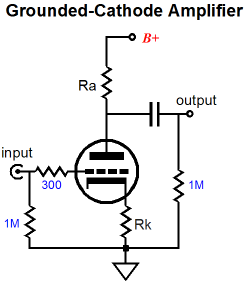
The gain of a grounded-cathode amplifier with either a truly grounded cathode or with a capacitor bypassed cathode resistor is found by using the following formula: Gain = mu∙Ra / (Ra + rp), where Ra is the plate resistor. If Ra equals zero, then the gain also equals zero. If Ra is infinitely large in value (i.e. a constant-current source), the gain is effectively the mu of the triode, as infinity over infinity plus rp is effectively equal to 1. Since mu = gm∙rp, we can rewrite the gain formula thus: Gain = gm∙rp∙Ra / (Ra + rp), Which we can reduce to Gain = gm∙R, where R is the plate resistor in parallel with the plate resistance, in other symbols Ra||rp, or put more traditionally: rp∙Ra / (Ra + rp). Since infinity in parallel with rp equals rp, the gain would equal gm against rp, which was the definition of mu. This is why we came up with the variable mu in the first place: it was a handy way of knowing what the maximum gain could be realized with a given triode, given an infinitely large plate resistor. For example, if you needed a gain of 40 from a single grounded-cathode amplifier, you would instantly know that a 6SN7 wouldn't cut it in this circuit. In other words, mu (amplification factor) was a quick shortcut, rather than "real" attribute of a triode. As I wrote in my article on the grounded-cathode amplifier:
Adding an unbypassed cathode resistor weakens the triode's transconductance, just as adding a source resistor to a MOSFET or an emitter resistor to a transistor weakens their transconductance. Conceptually, this makes perfect sense, as the cathode resistor is in series with the current flow through the triode and it creates a negative signal relative to the grid's input signal, so the cathode-to-grid voltage swings must be less than what the grid sees. (This is how degenerative feedback works.) For example, if the grid sees an input signal of that swings from -1V to +1V and the cathode imposes a voltage swing of -0.5V to +0.5V on the cathode resistor, the grid effectively loses half of its potential input signal. By the way, if we know the value of the cathode resistor, we then know the resulting effective transconductance in this example. For example, if the cathode resistor is 200 ohms, then the effective gm must equal 0.5V/200 or 0.0025A/V or 2.5mA/V or 2500µS (microsiemens). If all the +/1Vpk signal were superimposed upon the 200-ohm cathode resistor, then the effective gm would equal 1/200 or 5mA/V, even if the triode exhibited a tube-maual published gm of 40mA/V. The formula for the effective transconductance is gm' = mu / (rp + (mu + 1)Rk) And the effective plate resistance equals rp' = rp + (mu + 1)Rk The mu remains unchanged by the addition of the unbypassed cathode resistor, as the gm and rp are altered equally. Another way of viewing what a triode's mu is to think of it as a measure of the relative effectiveness of the grid over the plate in controlling the conduction of current through the triode. In other words, the mu equals how many times bigger a change in plate voltage is needed to cancel a change in grid voltage. For example, if a triode has a mu of 10, the plate voltage must go down by 10V for every +1V is applied to the grid in order to keep the idle current unchanged. Or put differently, to match the same increase in current conduction that results from increasing the grid voltage by +1V the plate voltage must increase by +10V.
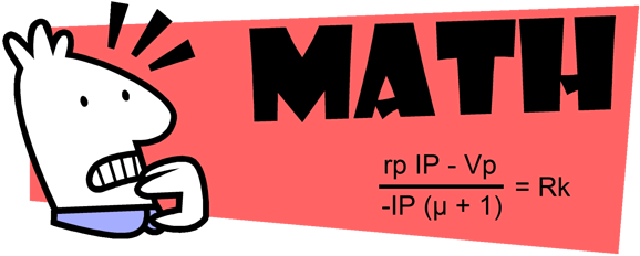
Speaking of idle current in a grounded-cathode amplifier, given a grounded cathode (no cathode resistor), what grid-bias voltage is required to establish a desired idle current. The following formula reveals the relationship: Vg = (rp∙Iq – Vp) / mu, where Vg is the grid-bias voltage and Iq is the idle current and Vp is the cathode-to-plate voltage. What value of a cathode resistor would achieve the same idle current? The formula must take into account that the cathode-to-plate decreases due to the cathode resistor's voltage drop, so the formula includes (mu + 1) in the denominator, rather than just mu. Rk = (rp∙Iq – Vp) / -Iq(mu + 1) For example, given a triode with a mu of 10 and an rp of 1k and B+ voltage of 100Vdc (no plate resistor is used in this example), a cathode resistor of 818.2 ohms would be needed to achieve an idle current of 10mA. Say that you wish to include the plate resistor in the formula, how would you proceed? Well, you know what the desired idle current is and thus you also know what the voltage drop across the plate resistor will, because of Ohm's law. In other words, you know that Vp in the old formula will now equal Vb+ - Iq x Ra, so you can replace Vp with this snippet: Rk = (rp∙Iq – (Vb - Iq∙Ra)) / -Iq(mu + 1) or after simplifying Rk = (rp∙Iq – Vb + Iq∙Ra) / -Iq(mu + 1) In theory, it doesn't matter whether the cathode resistor is bypassed by a large-valued capacitor or not. In reality, however, you can expect a small amount of leakage current from an electrolytic capacitor. And, of course, we can use a blend of fixed bias voltage and cathode bias resistance, but that would result in a slightly more complex formula. Sometimes we need an exact amount of gain from a grounded-cathode amplifier. To find the required formula only involves solving for either the cathode resistor or the plate resistor's value from the following formula: Gain = mu∙Ra / (Ra + rp + (mu + 1)Rk), where Rk is unbypassed. If Rk is bypassed, then the following formula is used. Gain = mu∙Ra / (Ra + rp) Solving for Ra with this formula results in: Ra = rp∙Gain / (mu – Gain) Solving for Rk with the previous formula results in: Rk = mu∙Ra / (mu + 1)Gain – (Ra + rp) / (mu + 1) While on the topic of grounded-cathode amplifiers, let's take a look into how we might get the maximum output voltage swing from a given triode in a grounded-cathode amplifier with a truly grounded cathode. Three states of current conduction must be considered: the idle current, the maximum current conduction, and zero conduction. The last is the easiest to evaluate, as we know it equals 0mA. The maximum current conduction seems a bit paradoxical, as we could always conduct more current, with a great positive voltage imposed on the grid. But if we limit ourselves to no grid voltage greater than 0V, no positive grid voltage in other words, then the maximum current conduction is equal to Vp/rp. Now, Vp is the cathode-to-plate voltage, not the B+ voltage. And since we do not know the maximum current conduction, how can we know the maximum plate voltage, as the plate-resistor voltage drop isn't known? The workaround is to take the B+ voltage and divide it by the sum of the rp and Ra. Ipk = Vb / (Ra + rp) Then we halve this amount to get the required idle current. Iq = Ipk / 2 This ensures the biggest output voltage swing for that triode with that plate resistor value and with that B+ voltage. Ideally, to get the biggest power output into the plate resistor, the plate resistor should be twice as large as the plate resistance, the famous 2rp in other words; and the idle current must result in the triode seeing 2/3 of the B+ voltage at idle. The grounded-cathode amplifier's output impedance depends on the plate resistor value, the triode's rp, and whether or not if it sees an unbypassed cathode resistor. In the case of a truly grounded cathode or a bypassed cathode resistor, the output impedance is: Zo = Ra || rp If the cathode resistor is unbypassed, the formula must include its resistance: Zo = Ra || [rp + (mu + 1)Rk] Its PSRR is found realizing that the plate resistor and the triode's rp define a two-resistor voltage divider, so with a grounded cathode or an unbypassed cathode resistor: PSRR (in dB) = 20Log[rp / (Ra + rp)] If the cathode resistor is unbypassed: PSRR (in dB) = 20Log[(rp + (mu + 1)Rk) / (Ra + rp + (mu + 1)Rk)] What about the cathode follower, White cathode follower, grounded-grid amplifier, SRPP, Aikido, and cascode circuits? They will have to wait. But as 90% of tube-based gear holds a grounded-cathode amplifier, getting this super simple circuit under one's belt is essential. I once received an e-mail from a reader who told of his erstwhile tube guru not knowing how changing the cathode resistor's value would change the idle current of an output tube, not knowing whether more resistance meant less or more conduction. Such a tube guru doesn't deserve any disciples. Once you have played around with these formulas, your only fear should be having to give a speech on this topic in front of 100 tube-lovers. Next Time
* From page 30 of his book, Lost in the Cosmos: The Last Self-Help Book. © 1983, McGraw-Hill Ryerson. I love this book. It is funny, insightful, smutty, puzzling, and truly unique. He asks many interesting questions and give many alternate answers, but does not tell which is correct. If you can answer all (or any) of the following questions he poses, you probably do not need to read his book. But for the rest of us, it's a great ride. Why the Self Wants to Get Rid of Itself How the Self Tries to Inform Itself by Possessing Things which do not Look like the Things They’re Used as Why Most Women, and Some Men, are Subject to Fashion How the Self, Which Usually Experiences Itself as Living Nowhere, is Surprised to Find that it Lives Somewhere Why the Self is so Afraid of Being Found Out Why the Self is so Afraid of Being Stuck with Another Self How the Self Tries to Escape its Predicament How Two Selves Confronting Each Other can Miscalculate, Each Attributing a Putative and Spurious Reality to the Other and Trying to Match it, with the Consequence that Both Selves Become Non-selves Why is it that One’s Self often not only does not Prefer Sex with one’s Chosen Mate, Chosen for His or Her Attractiveness and Suitability, even when the Mate is a Person well known to one, knowing of one, loved by one, with a Life, Time, and Family in common, but rather prefers Sex with a New Person, even a Total Stranger, or even Vicariously through Pornography (in the root sense of envy: invidere, to look at with malice) Why it is that the Self—though it Professes to be Loving, Caring, to Prefer Peace to War, Concord to Discord, Life to Death; to Wish Other Selves Well, not Ill—in fact Secretly Relishes Wars and Rumors of War, News of Plane Crashes, Assassinations, Mass Murders, Obituaries, to say nothing of Local News about Acquaintances Dropping Dead in the Street, Gossip about Neighbors Getting in Fights or being Detected in Sexual Scandals, Embezzlements, and other Disgraces Why the Self is the only Object in the in the Cosmos which Gets Bored Whether the Self is Depressed because there is Something Wrong with it or whether Depression is a Normal Response to a Deranged World How the Self can be Poor though Rich How the Self Characteristically Places itself vis-à-vis the World, particularly through modes of Transcendence and Immanence Reentry Problems of the Transcending Self, or Why it is that Artists and Writers, Some Technologists, and indeed Most People have so much Trouble Living in the Ordinary World How Scientists Don’t Have to Take Account of Themselves and Other Selves in their Science and Some Difficulties that Arise when they have to Why the Autonomous Self feels so Alone in the Cosmos that it will go to any Length to talk to Chimpanzees, Dolphins, and Humpback Whales Why Carl Sagan is so Anxious to Establish Communication with an ETI (Extraterrestrial Intelligence) //JRB
|
I know that some readers wish to avoid Patreon, so here is a PayPal button instead. Thanks.
John Broskie
And
High-quality, double-sided, extra thick, 2-oz traces, plated-through holes, dual sets of resistor pads and pads for two coupling capacitors. Stereo and mono, octal and 9-pin printed circuit boards available.
Designed by John Broskie & Made in USA Aikido PCBs for as little as $24 http://glass-ware.stores.yahoo.net/
The Tube CAD Journal's first companion program, TCJ Filter Design lets you design a filter or crossover (passive, OpAmp or tube) without having to check out thick textbooks from the library and without having to breakout the scientific calculator. This program's goal is to provide a quick and easy display not only of the frequency response, but also of the resistor and capacitor values for a passive and active filters and crossovers. TCJ Filter Design is easy to use, but not lightweight, holding over 60 different filter topologies and up to four filter alignments: While the program's main concern is active filters, solid-state and tube, it also does passive filters. In fact, it can be used to calculate passive crossovers for use with speakers by entering 8 ohms as the terminating resistance. Click on the image below to see the full screen capture.
Tube crossovers are a major part of this program; both buffered and un-buffered tube based filters along with mono-polar and bipolar power supply topologies are covered. Available on a CD-ROM and a downloadable version (4 Megabytes). |
|||


| www.tubecad.com Copyright © 1999-2013 GlassWare All Rights Reserved |