| John Broskie's Guide to Tube Circuit Analysis & Design |
07 September 2013 The Return of the Unbalancer
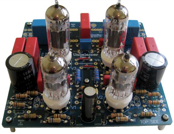
New Unbalancer PCB
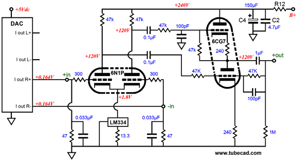
This will be welcome news to many audiophiles, particularly for those who need to convert their DAC's balanced output to an unbalanced output signal, as the Unbalancer can readily receive its balanced signal. If a stand-alone DAC already holds unbalanced outputs, why should I bother using its balanced outputs? The answer is that the balanced outputs are usually taken earlier in the circuitry chain, which allows us to avoid having our delicate signal passing through anymore OpAmps. The Unbalancer can also be used inside the DAC enclosure, where it can take the place of the OpAmps. For the most part, DAC ICs come in three flavors: current-out, voltage-out, and a hybrid of sorts that functions as a blend of current- and voltage-out. If the Unbalancer used directly with a voltage-output DAC’s balanced outputs, very little gain is needed, but some post high-frequency filtering will be desirable. Often voltage-output DAC present a large DC offset, usually about half of their positive power-supply voltage. This DC offset is not a problem and no input coupling capacitors are needed, as the Unbalancer input stage's constant-current source will simply absorb the DC offset. If a current-output DAC is used, then usually high gain will be required, as these DACs assume a near zero ohms impedance at their outputs. Well, we can get away with using two low-resistance load resistors. The DAC’s varying current output into these low-valued resistors creates a small voltage signal that must be amplified greatly, so a high-mu input tube should be used, such as the 6N1P or 12AT7, 12AX7, 6072, 5965.
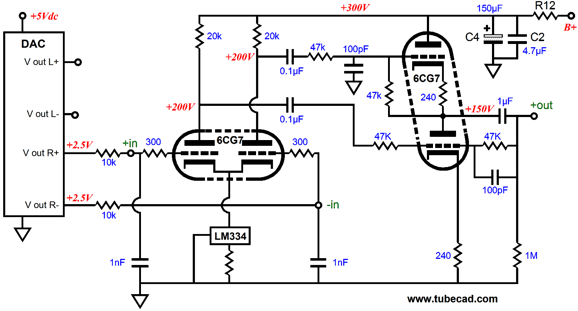
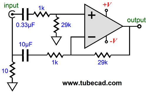
The set up for a voltage-output DAC looks same, except that the 47-ohm resistors have been replaced by 1nF capacitors and two 10k resistors are placed in series with the DAC outputs and the Unbalancer's inputs.
These added resistors will define a 160kHz low-pass filter with the 1,000pF capacitors. A second low-pass filter is imposed by the 47k resistors and 100pF capacitors in the output stage of the Unbalancer. (The CCS's set resistor's value should be 6.81 ohms in this example.)
The Unbalancer as an Unbalanced Line Stage Amplifier
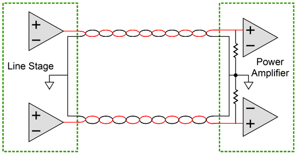
Because the two grounds in the line stage tie together in the power amplifier, signal current from one channel can take two paths back to the line stage. (The same thing happens in the line stage and its signal inputs, such as CD players or phono stages.)
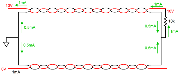
Note how the audio signal in just one channel returns down both ground conductors. For example, if 10V is present on one channel, the current flow through the power amplifier's 10k input resistor (or volume potentiometer) will equal 1mA, half of which will travel through both ground leads. Ideally, what happens exclusively in one channel, should remain in one channel. An isolation transformer at the power amplifier's (or line stage's) input will prevent one channel's signal-induced current flow to its channel. My solution, which I used in a stereo solid-state power amplifier that I built 30 years ago, was the following.
Well, a few months ago, I finally set up an Unbalancer as an unbalanced line-stage amplifier by using this setup:
Since the Unbalancer's input and BCF output stages offer excellent common-mode rejection (CMRR), hum and noise that are equally present on the input signals hot and ground connection are ignored. And the signal from on one channel will much prefer to complete its current path back to its source via that channel's ground lead, as it will only see milliohms of resistance rather than the 20-ohms of resistance bridging the channels' grounds within the Unbalancer's two 10-ohm resistors. (The house can complicate things, as often audio gear simply "grounds" its signal ground to the house ground via the power cord's third prong. The result might be safe, but it is certainly a mess when it comes to keeping our delicate audio signals pure.) I was quite impressed by how well the Unbalancer worked in this application. I used the JJ ECC802 (12AU7 long plates) tubes as input tubes and JJ ECC99 as the output tubes. (I am sure that I could configure a phase selection switch, but I haven't tried to yet.) The problem is that I am psychologically and logically invested in this setup working well, so a double-blind test should be preformed on it and me. For example, a relay could short out the two 10-ohm resistors. By the way, here is a quick test. Unplug all the signal sources from your line-stage amplifier. Then, attach a voltmeter set to read AC voltage to the line-stage amplifier and each signal source's ground barrel on the RCA jack. Ideally, oVac should be the result. Sadly, this is seldom the result. The next step is flip the power-cord plug on the signal source, if possible. Keep the orientation that results in the least AC voltage between the two pieces of gear.
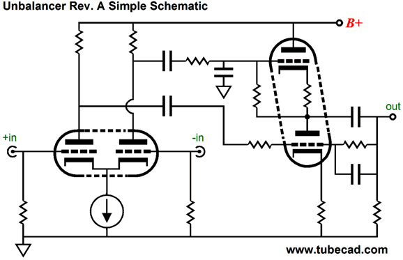
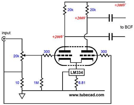
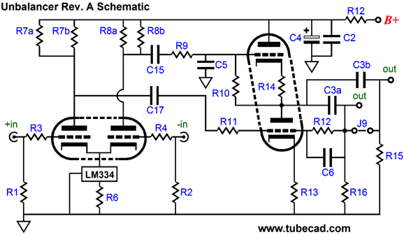
No Power Supply The new Unbalancer PCB does include some new features, such as two sets of output coupling capacitors and doubled up plate resistors. In addition, the circuit now holds two internal coupling capacitors, which allows more freedom in setting the input stage's DC operating points. (The new coupling capacitor can be replaced by a jumper wire to restore the circuit to its old configuration.) Note in the above schematic with the voltage-out DAC, how the 6CG7-based input stage does not spilt the B+ voltage, as the 6CG7 plates see 200Vdc, while the B+ voltage is 300Vdc. Here is the actual Unbalancer schematic.
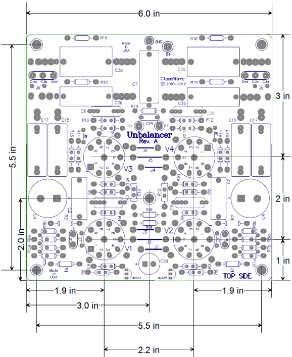
The GlassWare Unbalancer 9-pin stereo PCB is extra thick, 0.094 inches (inserting and pulling tubes from their sockets won’t bend or break this board), double-sided, with plated-through heavy 2oz copper traces. In addition, the PCB is lovingly and expensively made in the USA. The boards are 6 by 6 inches, with five mounting holes, which helps to prevent excessive PCB bending while inserting and pulling tubes from their sockets. The JJ ECC802 and ECC99 tubes work quite well in the Unbalancer. The resulting gain is a little over +20dB. Other tubes that would work well are the 6AQ8, 6CG7, 6DJ8, 12BH7, 5963. The Unbalancer PCB and kits are now available at the GlassWare Yahoo store.
Next Time
//JRB |
I know that some readers wish to avoid Patreon, so here is a PayPal button instead. Thanks.
John Broskie
And
High-quality, double-sided, extra thick, 2-oz traces, plated-through holes, dual sets of resistor pads and pads for two coupling capacitors. Stereo and mono, octal and 9-pin printed circuit boards available.
Designed by John Broskie & Made in USA Aikido PCBs for as little as $24 http://glass-ware.stores.yahoo.net/
The Tube CAD Journal's first companion program, TCJ Filter Design lets you design a filter or crossover (passive, OpAmp or tube) without having to check out thick textbooks from the library and without having to breakout the scientific calculator. This program's goal is to provide a quick and easy display not only of the frequency response, but also of the resistor and capacitor values for a passive and active filters and crossovers. TCJ Filter Design is easy to use, but not lightweight, holding over 60 different filter topologies and up to four filter alignments: While the program's main concern is active filters, solid-state and tube, it also does passive filters. In fact, it can be used to calculate passive crossovers for use with speakers by entering 8 ohms as the terminating resistance. Click on the image below to see the full screen capture.
Tube crossovers are a major part of this program; both buffered and un-buffered tube based filters along with mono-polar and bipolar power supply topologies are covered. Available on a CD-ROM and a downloadable version (4 Megabytes). |
||


| www.tubecad.com Copyright © 1999-2013 GlassWare All Rights Reserved |