| John Broskie's Guide to Tube Circuit Analysis & Design |
| 05 July 2014 Constant-Current-Source Amplifiers
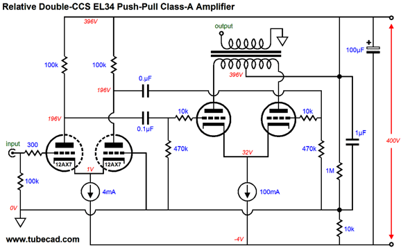
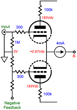
The solution was the two-resistor voltage divider (made up from the 1M and 10k resistors in series), which gave the input stage's CCS more voltage headroom. Well, what if the input tube was a 12AU7 (or some other medium-mu twin triode, such as the 6CG7, 6SN7, ECC99, or 5687)? In this case, the cathode voltage would be high enough to use an LM334 CCS. Thus, the two-resistor voltage divider is no longer needed.
The 10k resistor and 1µF capacitor, however, are still needed, as they isolate the power-supply ripple to the bottom of the constant sources, preserving the excellent PSRR.
If the 10k resistor is removed, we also end up removing the RC filter, so the power supply noise is no longer isolated below the constant-current sources.
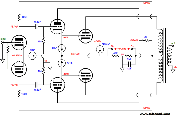
With the B- attaching directly to ground, all the power-supply noise becomes located at the B+ connection. In DC voltage terms, these two setups are identical; but in AC terms, they are opposites. This tube power-amplifier circuit also benefits from the use of the small but all so mighty 6BQ5/EL84, which only requires a fraction of the grid-voltage swing that other power tubes, such as the 6L6 or 2A3, demand. All in all, this would make an excellent-sounding little amplifier. If more power is required, which always seems to be true, then both more input-stage gain and more robust output tubes will be needed.
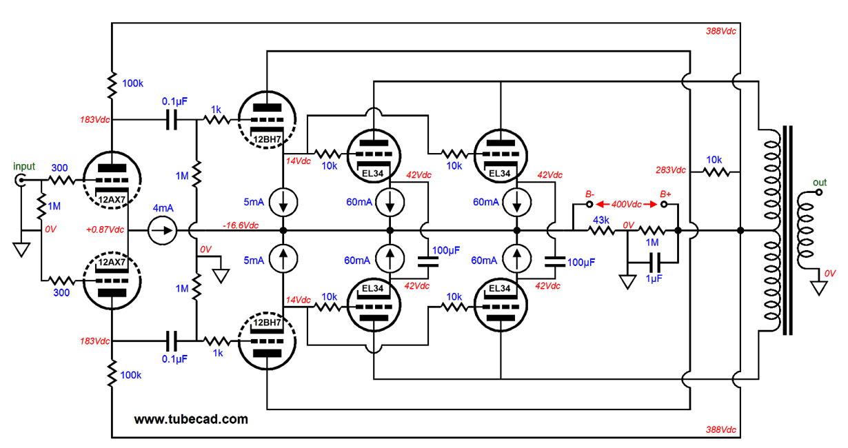
The first requirement is not as easy to satisfy as you might imagine. True, a 12AX7's high mu of 100 certainly helps in the gain requirement, but its small trickle of plate current might prove too wimpy to drive the output-tube's input capacitance to full output at high frequencies. This particularly true if the output tubes are triodes, such as the 2A3 or 300B, or triode-connected pentodes, such as the EL34 or KT88. The workaround is to use a cathode follower after the 12AX7, as it will both shield the 12AX7 from the output stage and will allow the cathode follower's low output impedance and high current draw to cut through the output-tube's input capacitance. A robust tube, such as the 12BH7 or 5687, should be used in the cathode-follower position. In addition, the DC coupling of the cathode follower outputs to the output-tube's grids means that capacitor-blocking distortion cannot occur, as there is no coupling capacitor to to charge up excessively when the output-tubes enter positive grid voltages. But now we have a new problem: both the cathode-follower triodes and the output tubes would have to be tightly matched to use a single CCS on the output stage. The workaround is to give each output tube its own CCS. Well, that is the first step, but it is not enough, as the two output-tube cathodes must be tied together, at least in AC terms, or there is no amplification. What do you mean no amplification? Just that: no amplification of the input signal at the grid will obtain at the plates, as the CCS maintains a fixed current flow through the output tube. No variation in current flow, no amplification. Thus, the capacitor that bridges the two cathodes. The average current flow is fixed, but each output tube will undergo large variations in current swing, as prompted by the input signal. Okay, now that you have the general idea, let's move on to four output tubes.
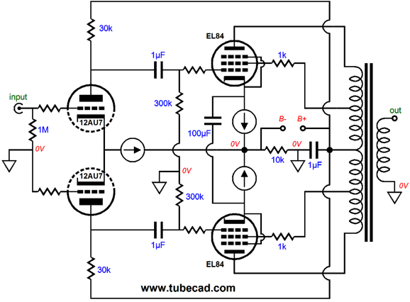
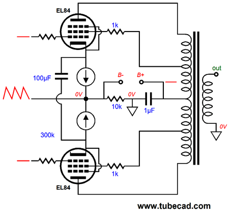
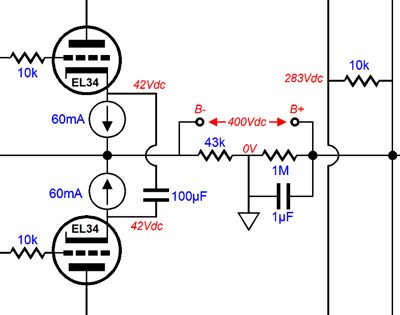
In the above schematic, we see four output-tubes and four 60mA CCS, one for each output tube, and two cathode-bridging capacitors. How big does this "bridge" capacitor need to be? It depends on the output tube that is used, but a safe value would start at about 100µF, with more being better. (I would use non-polarized electrolytic capacitors that were bypassed by a 1µF film or PIO capacitor.) Another key feature to this amplifier is the relatively larger voltage division provided by the 43k and 1M resistors than what the 10k and 1M pairing provided. Why the change? The two constant-current sources that load the 12BH7-based cathode followers must displace slightly more voltage than the output tubes's DC grid-to-cathode voltage, else the cathode follower will bottom out before the output tube nears its cutoff grid voltage. (This is something that SPICE simulations are likely to hide, as the current source in SPICE is just that: a source of current that pours forth current, much as a battery pours forth voltage. In other words, this is an idealized function which cannot be bought at your local electronic store or anywhere else on Earth. In other parts of our galaxy, who knows? What we call a constant-current source is really a current regulator, which does not create current, but limits its flow to a preset value. In SPICE, a current source in parallel with a resistor will produce a voltage drop across the resistor; in contrast, a solid-state CCS in parallel with a resistor—and connecting to nothing else—produces nothing. It can't; it doesn't produce current flow; it limits current flow.) By using the 43k resistor instead of the 10k resistor, the cathode follower CCS see a voltage drop over a little over 30V. In turn, the output tube CCSs also see a greater voltage drop, which means that the output tubes get less plate voltage to play with. In other words, we had to steal some of the available cathode-to-plate voltage to give to the CCSs. No free lunches.
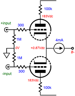
While we are at it, note the 10k resistor that connects the B+ voltage to the two cathode-follower plates. Why is it there? The 12BH7's maximum plate voltage is only 300V, so we need to reduce its plate voltage by 100V. (If an ECC99 were used, the we probably could forgo the use of the 10k series resistor.) Moving backwards to the input stage, we can easily change to a balanced input signal, with two phases, as the following schematic shows.
Or, we could use the bottom input grid to inject some negative feedback from the output transformer secondary.
No doubt, many instantly imagine that LM317 voltage regulators will be used in the construction of the constant current sources. Well, they could be, but they do not have to be, as we could use NPN transistors in their stead.
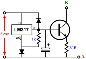
One problem with the above circuit is that all seven transistor bases will draw quite a bit of current, as will the zener diode, which means that the resistor that feeds the zener will end up being lower in value than we might want, as it will waste too much power and dissipate too much heat. One workaround would be to use an LM317 to drive all the bases, allowing us to lose the zener, as the LM317 contains its own voltage reference. In fact, we can lose the power resistor by using an unused 5Vac rectifier winding to power the LM317, as shown below.
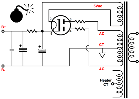
This low-voltage power supply attaches to the B- connection of the main power supply. Speaking of the main power supply, why is the following power supply flawed?
Sure, it looks good, but it holds a major wiring mistake. Don't see it? Look at where the transformer's center tap attaches to the ground. Bingo. We have located ground elsewhere and this setup moves to the wrong place. Ground must only be located between the 43k and 1M resistors. Effectively the power supply is floating, although it can be shared between two channels, unlike the floating power supplies in a Circlotron. The LM317 puts out a 1.25V output voltage relative to its adjustment pin, which is a bit low for the all the transistor-based constant-current sources, so a 1N4001 rectifier is placed in series with the LM317's adjustment pin to bump the LM317's output voltage up by about 0.7Vdc, bringing the output to about 1.95Vdc.
A 1k resistor might have to be added, from the LM317 output pin to its adjustment pin; and it never hurts to add a capacitor-discharge diode to mix.
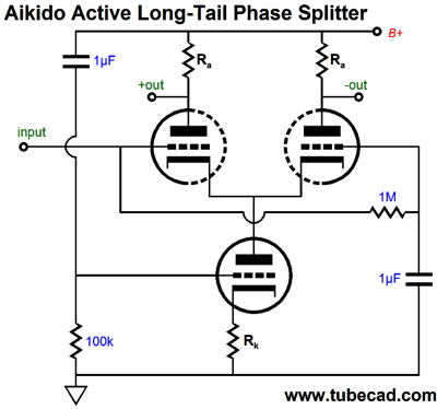
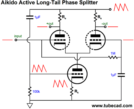
Aikido Active-Tail Phase Splitter Zo = (mu + 1)Rk + rp where mu is the triode's amplification factor and rp is its plate resistance. This active load presents two resistances: an AC and a DC resistance, with the AC resistance (impedance) being much greater.
Where the name "Aikido" enters the picture is in the active-load triode's grid not terminating, in AC terms, to ground, but to the B+ connection. This means that 100% of the power-supply noise will appear at the grid, which in turn means that the active-load triode will amplify this "signal" and invert it at its plate, which will cause the noise signal to be relayed to the two phase-splitter outputs—ideally, canceling when this signal mixes with the power-supply noise that would otherwise leak out.
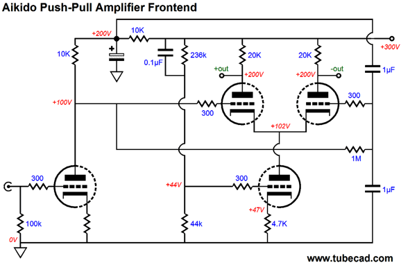
Cathode resistor Rk should be roughly one fourth as large in value as each Ra plate resistor. Invariably, it will end up being a tad less than 1/4 as big, as the active-load triode does not fully realize unity gain at its cathode. Below is a complete frontend for a push-pull output stage. Two twin-triode tubes are used, such as 6SN7 or 12AU7 tubes. (A 12DW7 could be used on the bottom, if the 12AX7 section were used for the input stage and the 12AU7 section were used for the active-load triode.)
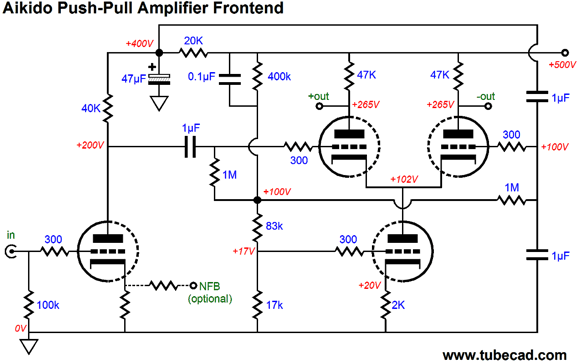
Note the two 1µF capacitors in series with each other. They both bypass the input stage's electrolytic capacitor and function as 50% AC voltage dividers, giving the un-driven phase splitter grid an equal sampling of leaked power-supply noise as the driven grid sees from the input stage, furthering the PSRR enhancement. By the way, we can alter the circuit to accommodate larger phase-splitter output voltage swings, for output tube like the 2A3 or 300B, which require the bigger grid swings.
Since the 2k cathode resistor is far smaller than the Rk/4 ratio we had used before, the active-load triode cannot be given 100% of the power-supply noise at its grid, or we will end up with a worse PSRR figure. In this example, the 83k and 17k resistors provide the required voltage division. Also note the higher B+ voltage
Next Time
For those of you who still have old computers running Windows XP (32-bit) or any other Windows 32-bit OS, I have setup the download availability of my old old standards: Tube CAD, SE Amp CAD, and Audio Gadgets. The downloads are at the GlassWare-Yahoo store and the price is only $9.95 for each program. http://glass-ware.stores.yahoo.net/adsoffromgla.html So many have asked that I had to do it. WARNING: THESE THREE PROGRAMS WILL NOT RUN UNDER VISTA 64-Bit or WINDOWS 7 & 8 or any other 64-bit OS. I do plan on remaking all of these programs into 64-bit versions, but it will be a huge ordeal, as programming requires vast chunks of noise-free time, something very rare with children running about. Ideally, I would love to come out with versions that run on iPads and Android-OS tablets.
//JRB |
I know that some readers wish to avoid Patreon, so here is a PayPal button instead. Thanks. John Broskie
Kit User Guide PDFs
E-mail from GlassWare Customers
High-quality, double-sided, extra thick, 2-oz traces, plated-through holes, dual sets of resistor pads and pads for two coupling capacitors. Stereo and mono, octal and 9-pin printed circuit boards available.  Aikido PCBs for as little as $24 http://glass-ware.stores.yahoo.net/
Support the Tube CAD Journal & get an extremely powerful push-pull tube-amplifier simulator for TCJ Push-Pull Calculator
TCJ PPC Version 2 Improvements Rebuilt simulation engine *User definable
Download or CD ROM For more information, please visit our Web site : To purchase, please visit our Yahoo Store: |
|||


| www.tubecad.com Copyright © 1999-2014 GlassWare All Rights Reserved |