| John Broskie's Guide to Tube Circuit Analysis & Design |
03 September 2014
New Regulated Low-Voltage
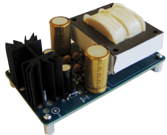
Tr-PS-1: Regulated Low-Voltage Power Supply
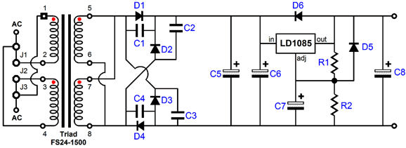
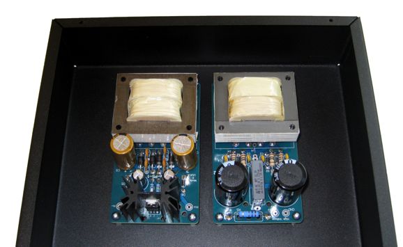
The key feature to split-bobbin, flat-pack transformer designs is their low capacitance between its primary and secondary, which inhibits the transmission of high-frequency noise from the primary to the secondary, as the core is too frequency-limited to allow the this coupling on its own. The Tr-PS-1 PCB is only 5 " by 2.8 " and, like all GlassWare PCBs, is extra thick (0.094 in), US-made, with heavy 2-ounce copper traces. The PCB holds a 3A, low-drop-out (LDO), adjustable voltage regulator, the LD1085, which idles at 10mA with no external load and is able to deliver 1.5A @12Vdc into an external load. The rectifiers used are ultra-fast MUR410G types, each of which are shunted by a 0.1µF ceramic capacitor to reduce RFI creation.
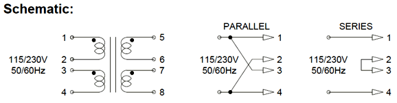
As you can see from the Tr-PS-1 schematic shown above, using jumpers J1 & J3 places the two primary windings in parallel, for use with 115Vac wall voltage; using only jumper J2, in series, for use with 230Vac wall voltage.
The goal behind both the Tr-PS-1 & Tr-PS-2 power supplies was to make building tube projects easier; hook-up and play, if you will.
The complete Tr-PS-1 kit is only $49 USD and is available now at the GlassWare-Yahoo store. It includes all the parts, including the user guide, the transformer, and four sets of standoffs and screws and O-rings. It can be set to either 9Vdc, 12Vdc, or 12.6Vdc and offers the option of a 1.5in or 2.5in heatsink.
Ultra-Empathic Configuration
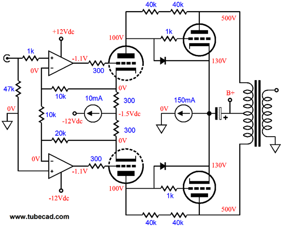
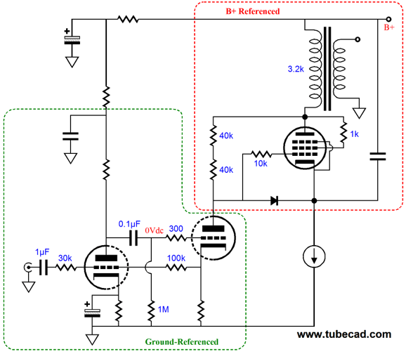
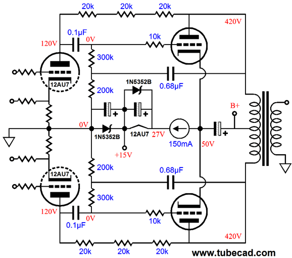
Note the phase and amplitude relationships within the above schematic. The input triodes see a balanced pair of input signals that that becomes both amplified and inverted at the plates. The output tubes then further amplify the signal and the output transformer reduces the huge voltage swings and increases the relatively meager current swings at its secondary, allowing the the high-impedance tubes to drive low-impedance speakers. The key feature is the feedback resistors (Rfb), which relay the voltage swings at the plates to the output tube's grids. Well, in the above schematic, they only relay a portion of the plate voltage swings, as the input triodes own plate resistance (rp) creates a two-resistance voltage divider with the Rfb resistors, so only a partial relaying occurs. Not, empathic enough, so let's return to the circuit from the last post.
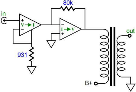
This output stage runs differently from all other push-pull, transformer-coupled output stages in that the output stage is not a simple grounded-cathode, voltage amplifier, but a large current-to-voltage stage, an I-to-V stage. The driver stage is also different, being a voltage-to-current stage, not a voltage amplifier. The OpAmps controlling the triodes (6SN7) control the current flow through the triodes, not the voltage at their plates. In other words, the OpAmps deliver varying voltage to the driver stage grids, and then the driver stage delivers a varying output current at its plates, which the output stage converts to varying voltage at its plates. Effectively, the output tubes see 100% degenerative negative feedback, much in the same way as they would in a cathode-follower circuit. The result is much lower distortion and output impedance. Astute readers have no doubt spotted both the Ultra-Path connection of the power-supply capacitor and constant-current source's connection to the cathodes of the output tubes. Most tube fanciers would bypass the constant-current source with a large-valued capacitor, so why did I use this Ultra-Path arrangement instead? PSRR enhancement. Surprise, surprise. Actually, this should be something of a surprise, as the Ultra-Path arrangement usually worsens the PSRR figure, not improve it, as it feeds power-supply noise into the cathode, which the output then amplifies, in phase, at its plate.
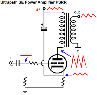
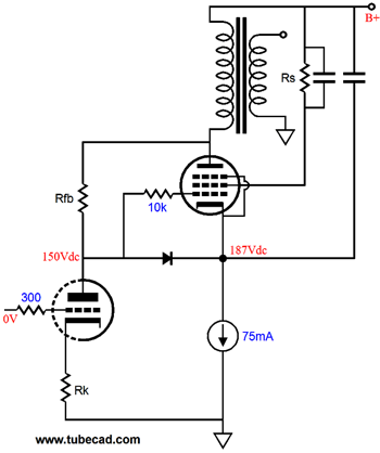
But in this circuit, we want all the power-supply noise present at the B+ connection to also be preset at the grids and cathodes of the output tubes. Welcome to the inverted world of B+ referenced, not ground referenced circuitry. The push-pull aspect might, however, make all this seem more complex than it actually is, so here is a single-ended amplifier arrangement Ultra-Empathically.
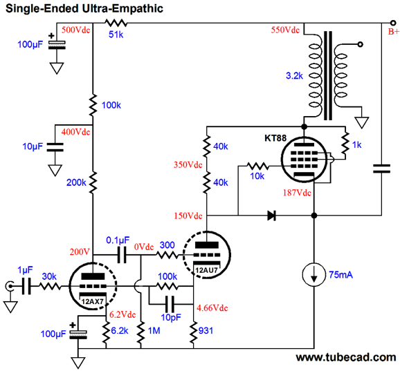
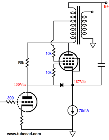
(The diode is a protection device that protects the output tube at turn-on, when the output tube is cold and not conducting and would prefer not to have its grid being 550V higher in voltage than its cathode. In other words, ignore it, for now.) The input triode, a 12AX7 (half of a 12DW7/7247/ECC832), is configured in a plate-follower topology or, what it is more commonly called, an inverting-amplifier topology. It functions, with the aid of the 12AU7 triode (the other half of a 12DW7/7247/ECC832), as a voltage-to-current converter, a V-to-I stage. One important feature to the V-to-I stage is its very high output impedance. This is important due to our desire of obtaining as much of the potential negative feedback from the KT88's plate to its grid as possible, thereby becoming more empathic. If a plain grounded-cathode amplifier were substituted for the V-to-I converter, the triode's relatively low plate resistance would form a two-resistor voltage divider with the 80k feedback resistor (the two 40k resistor in series), undoing much of the empathy. At the risk of making things harder to understand, rather than easier, here is a conceptual diagram of the Ultra-Empathic arrangement.
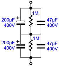
The 12AX7 and 12AU7 triode fit inside the first triangle; the KT88, the second triangle. The V-to-I converter transform voltage into current, while the V-to-I converter turns current into voltage, and the output transformer both reduces voltage swings and increases current swings. The constant-current source and Ultra-Path capacitor means that any power-supply noise present at the B+ connection will be relayed to the KT88's grid, which explains why a constant-current source, rather than a plain cathode resistor was used to bias the KT88. A big cathode resistor would only drag down the coupling of the power-supply noise to the cathode. In addition, the constant-current source allows easy auto-biasing of the KT88. I didn't mark the Ultra-Path capacitor's value, as it depends, mostly on your budget. Large-value polypropylene capacitors with 800V rating are now being sold, but the more likely setup is to place two 400V electrolytic capacitors in series, with accompanying two-resistor voltage divider and film bypass capacitors.
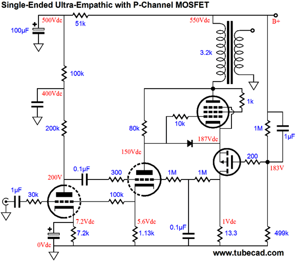
Another approach would be to to forgo brute force and get clever. For example, what if use a capacitance-multiplier circuit, so that a much smaller-valued capacitor could be used, say only 1µF.
The P-channel MOSFET provides a low output impedance at its source, to which the KT88's cathode attaches. The 1µF capacitor relays all the B+ noise to the MOSFET's gate, so all the B+ AC noise will appear at the KT88 cathode. An added sneaky move was to let the 12AU7 triode sample the current flowing through both the MOSFET and the KT88 via the 13.3-ohm resistor. If current rises, the voltage drop across this resistor also rises, which will cause the 12AU7 to draw more current, which in turn will pull down its plate voltage, thereby also decreasing the KT88's current conduction. Conversely, if current falls through the 13.3-ohm resistor, the voltage drop across this resistor also falls, causing the 12AU7 current flow to fall, making its plate voltage climb, increasing the KT88's current conduction as result, as its grid voltage rises as a result. What if we wish to use an ultra-linear configuration on the output tube? An Ultra-Linear, Ultra-Empathic amplifier, in other words. No problem, we just attach grid-2 (screen) to the ultra-linear tap on the output transformer's primary.
Okay, what if we want to run the pentode in pentode mode? Do we just attach a resistor to grid-2 and the B+ connection, along with a capacitor from grid-2 to ground? No, absolutely not. Unlike just about every other tube power amplifier, the Ultra-Empathic holds two, not one signal reference. The input stage is referenced to ground, but the output stage is referenced to the B+ connection.
Thus, grid-2 must also be referenced to the B+ connection.
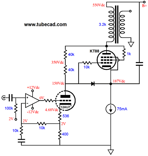
This might be the preferred way to set up the output stage, as pentode connection will yield the most gain and potential power. The distortion, however, will be slightly lower with a triode-connected pentode. Perhaps the 12DW7-based input stage is confusing you; it does look complicated. So, here is an OpAmp-based input stage.
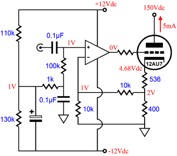
The OpAmp controls the 12AU7's current conduction. If that is not obvious, look at where the 10k feedback resistor attaches to the 400-ohm cathode resistor. As far as the OpAmp is concerned, that connection is the output, so it uses its considerable open-loop gain to force the voltage at this connection to be exactly twice the voltage that appears at its non-inverting input. The additional 536-ohm cathode resistor was added to allow the OpAmp's output to center at 0V, which will allow it the greatest symmetrical output voltages swings. By the way, we can lose the capacitor that terminates the feedback resistor string.
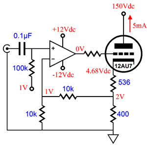
Note the voltage relationships. We start with 1Vdc at the OpAmp's non-inverting input pin, then we move on to the the same 1Vdc at its inverting input, and we end at the 2Vdc at the top of the 400-ohm cathode resistor. An important subtlety is to make sure that the 1V reference voltage that feeds the 100k input resistor comes up slowly, very slowly. Why? When first turned on, the 12AU7 will be cold and not conducting, but the OpAmp will be instantly on and will strive to establish the needed 2Vdc at the top of the 400-ohm cathode, so it will throw its output to +12V rail voltage. On the other hand, if 1V reference voltage develops slow enough, the cathode will have time to heat up and begin to conduct. How do we slow the 1V rise? Simple enough: use an RC filter with a big time constant. In fact, I would play around with a reference voltage that starts out negative and slowly climbs positive, such as the following.
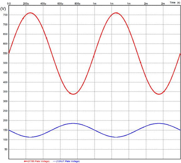
The OpAmp develops a gain of 2 (+6dB) at the connection to the 400-ohm cathode resistor. Thus, a 1Vpk input signal would develop a peak current swing of 2V/400 or 5mA, which would either double the idle current of 5mA or turn the 12AU7 completely off. In other words, the 1Vpk input signal is more than enough to drive the 12Au7 to full output. Speaking of full output, I ran some SPICE simulations on the Ultra-Empathic output stage. The following graph shows the KT88 and 12AU7 plate voltage swing at full output.
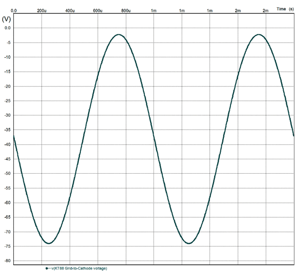
How do we know if this is the full output? We look at the graph of the KT88's grid-to-cathode voltage.
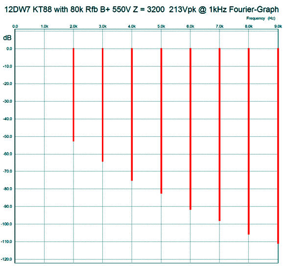
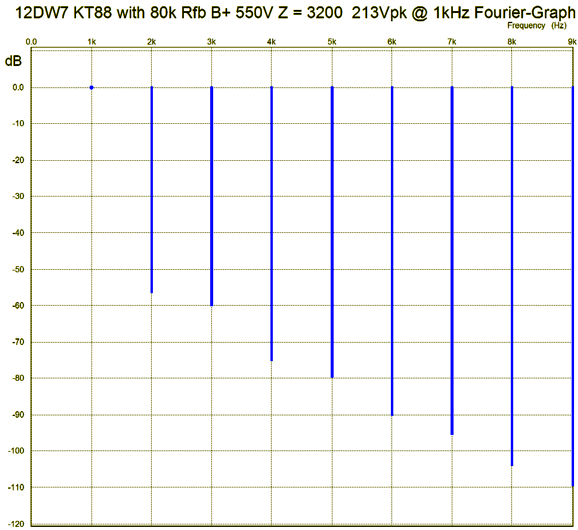
Note how close the grid gets to the oV line, beyond which lies positive grid voltages. Alternatively, we can look at the KT88's current plot, which would show when we hit a peak equal to twice the idle current through the output tube. The output transformer primary sees a peak voltage swing of 213V in this example, which implies 7W RMS with a 3,200-ohm primary impedance. Here is a distortion graph for just the KT88 in the output stage at full output, driven by a modulated current source, not a 12AU7.
This is particularly fine and it exhibits the wonderful single-ended harmonic structure so beloved by the ear. At 1W out, the distortion is below 0.1% and beautiful to behold. Well, I decided that I better show the results of including the 12DW7 frontend, and here is the fourier graph for the entire amplifier.
Shockingly similar. Indeed, the 2nd harmonic is even lower. How is that possible? More is always less, in terms of cascading circuitry, isn't it? Well, it seems that in this case we have some complementary distortion cancellation going on. Fascinating. In my opinion, the 3rd harmonic is the one to pay attention to, as it makes a bigger difference to the resulting sound than the 2nd harmonic. Now, I know many are still recovering from the paltry 7W of output. Do not be dismayed. If you bought this amplifier ready-made at some high-end boutique, for say $4,000, it would be advertised as producing 14W, as so many high-end audio companies have reverted to the old, cheating peak-watt ratings, which the FTC thought they had outlawed. Ha ha ha, as if... Okay, with tongue removed from my cheek, I would actually use two output tubes in parallel with a One Electron UBT-1 output transformer, a 1,600-ohm primary transformer, so I would get 14W RMS (or 28W high-end-tube-amp watts). The key point here is that it took a peak current swing of 3.1mA by the 12AU7-based stage to bring the amplifier to full output. (I had targeted 3mA in my mind, and I am astounded that I came so close. Pure luck no doubt, but he is a fool who doesn't take credit for his luck.) Another important point is that due to the Ultra-Empathic arrangement, the output impedance is low, very low. In SPICE simulations, the impedance at the KT88 plate was about 85 ohms, which is crazy low, the same as a KT88 would deliver at its cathode in a cathode-follower topology. Now, 85 ohms divided by the output transformer's impedance ratio, 3200/8, or 1:400, equals only 0.21 ohms at the secondary output. (Actually, the primary and secondary DCR resistances will undermine this low amount. Nonetheless, ) One thing that has bothered me from the start was the high cathode voltage on the KT88, as it was both wasteful and necessitated a fairly high B+ voltage, 550Vdc. The following variation uses some of that wasted voltage and runs a lower B+ voltage, yet produces the same amount of output power.
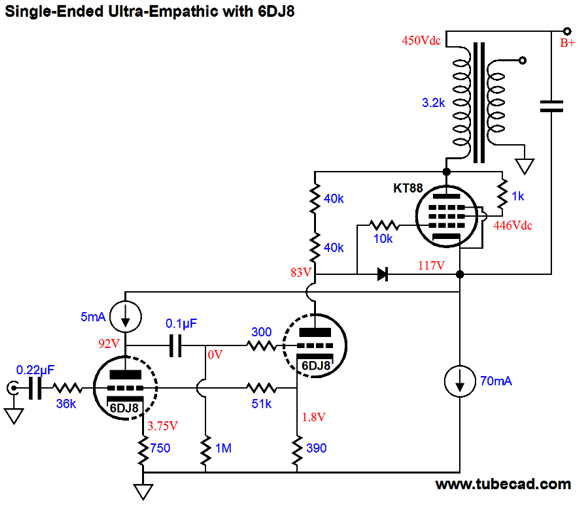
Very Loften-White, don't you think? The 6DJ8, due to its low plate resistance, doesn't need nearly as much plate voltage as the 12AX7 does. The 5mA constant-current source that load the input triode also helps us reduce the B+ voltage; in addition, it is needed to sidestep the huge amount of B+ noise at the KT88 cathode. Now, let's return to the original push-pull version.
My hope is that it no longer looks so strange, that you can readily see the two sets of feedback loops, and that (in the output stage) the constant-current source and the power supply capacitor shunting the constant-current source to the B+ connection, not ground, makes sense. In the pursuit of greater simplicity, let's lose the 10mA constant-current source and the -12Vdc power-supply rail.
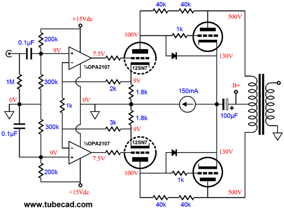
Okay, okay, I admit that it looks more complicated, not simpler. Note, however, that a mono-polar, 15Vdc power-supply now powers the dual OpAmp, not a bipolar power supply; and that the 10mA constant-current source has been replaced by two 1.8k cathode resistors, yet the fixed idle current through the 12SN7 remains in place. Yes, we switched from a 6SN7 to a 12SN7. Why? We can use the 15V power-supply to power the 12SN7's heater by placing an 8.2-ohm 2W or 3W resistor in series with the heater element. Alternatively, we could use a 15V zener in series with the 150mA constant-current source and get a "free" power supply for the OpAmp; of course, we cannot use this "free" 15V power-supply rail to power the 12SN7's heater element, not unless the constant-current source and the output stage idled at 300mA. We could, however, power a 12AT7, 12AU7, 12AX7, or 12DW7 tubes 150mA constant-current source.
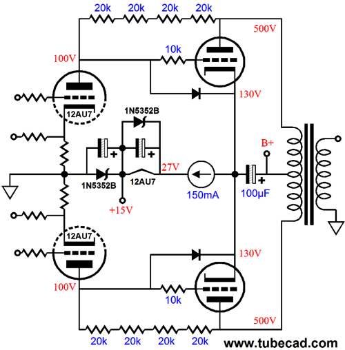
Why is there a 15V zener across the 12AU7's heater element? It is there for safety reasons. For example, what happens if the the 12AU7 is missing fro its socket? Not good, as the the output tubes will heat up and conduct, allowing the constant-current source to pull up the voltage where the heater element should be. The result will be that the shunting capacitor will charge up linearly beyond its nominal 16V voltage rating. Well, why can't we just use a higher voltage capacitor? WIthout the 12AU7 there to pull the 80k Rfb resistors down to 100V, the voltage on the output tube grids will be 500V, so we can expect the voltage on their cathodes to be close in value. Not good. The 50-cent zener prevents problems from developing by throwing a stop at +30V and no more than 15V across where the 12AU7 heater should be. Yes, we did add a coupling capacitor to what had been an otherwise DC-coupled amplifier throughout. My view is that this is wise move, as the last thing we want is DC offsets at the input to throw the amplifier out of whack. In addition, we do not want the amplifier to try to amplify low-frequency signals below its ability. Well, since we have now taken a sip from the cup of coupling capacitors, why not get drunk? We could place a coupling capacitor between the V-to-I stage, but we will also have to prevent the grid resistor that goes to ground from dragging down our 100% negative feedback. The following shows how this might be done.
The feedback resistors are no longer 80k, but 60k. Why? With the 420V B+ there wasn't enough plate voltage on the 12AU7 stage. Bear in mind that the 60k Rfb resistor is, in AC terms, in parallel with the 300k grid resistor, so the effective Rfb resistance is 50k, as 60k || 300K = 50K, as (60 x 300)/(60 + 300) = 50. The more I look at the circuit, the more inclined I am to up the voltage for the OpAmp, as 15V seems a tad too low; thus, I would replace the bottom 15V zener with a 20V zener. A 20V zener will get hot, as it must dissipate 3W, so a 10W device should be used.
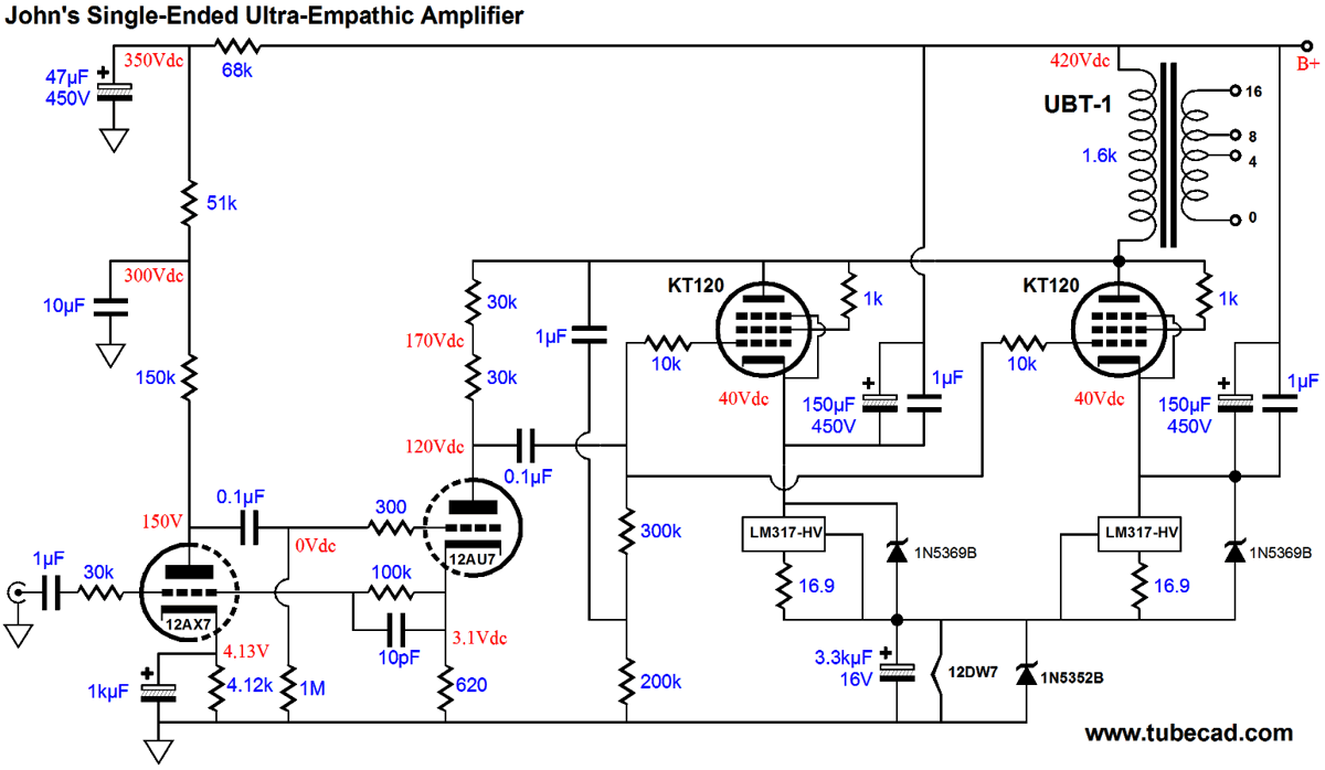
What Would John Do
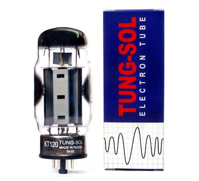
Yes it's single-ended, not push-pull and it uses KT120 tubes rather than KT88s and it uses two of them in parallel. Each KT120 will idle at 75mA, which against a 380V cathode-to-plate voltage equals 28.5W of heat, which a KT88 could take, but the KT120's 60W limit gives us less to worry about. Besides, I like the look of the new tube from Russia.
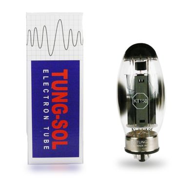
In contrast, the KT150's 70W plate dissipation isn't that much greater, but is an interesting looking tube.
Okay, enough tube fetish gawking and back to circuits. Note how two constant-current sources are used, one per output tube. While it would still be a good idea to use matched output tubes, the two independent constant-current sources grant us the peace of mind that with time and heavy use, the tube will still idle at the desired current. The two constant-current sources then sum up to pull 150mA up through the 12DW7's heater element. The 1N5352B (15V) zener is there for safety reasons and does not set the voltage drop across the heater element, the constant-current sources do that job. But is the 12DW7's heater opens up or is missing, the zener will limit the voltage drop across the shunting capacitor and give the output tubes a current path to ground. The two 1N5369B (51V) zeners are also there for safety's ake, as the large bypass capacitor must be charged up at startup and they would otherwise present too much voltage to the LM317-HV regulators. The relatively low B+ voltage of 420V makes capacitor selection much easier, as you can readily buy 450V, 500V, and 630V capacitors. All in all, I am sure that this would prove to be a giant-killing amplifier and I would love to hear what Ultra-Empathic sounds like.
Next Time
Since I am still getting e-mail asking how to buy these GlassWare software programs:
For those of you who still have old computers running Windows XP (32-bit) or any other Windows 32-bit OS, I have setup the download availability of my old old standards: Tube CAD, SE Amp CAD, and Audio Gadgets. The downloads are at the GlassWare-Yahoo store and the price is only $9.95 for each program. http://glass-ware.stores.yahoo.net/adsoffromgla.html So many have asked that I had to do it. WARNING: THESE THREE PROGRAMS WILL NOT RUN UNDER VISTA 64-Bit or WINDOWS 7 & 8 or any other 64-bit OS. One day, I do plan on remaking all of these programs into 64-bit versions, but it will be a huge ordeal, as programming requires vast chunks of noise-free time, something very rare with children running about. Ideally, I would love to come out with versions that run on iPads and Android-OS tablets.
//JRB |
I know that some readers wish to avoid Patreon, so here is a PayPal button instead. Thanks. John Broskie
Kit User Guide PDFs
And
High-quality, double-sided, extra thick, 2-oz traces, plated-through holes, dual sets of resistor pads and pads for two coupling capacitors. Stereo and mono, octal and 9-pin printed circuit boards available.
Designed by John Broskie & Made in USA Aikido PCBs for as little as $24 http://glass-ware.stores.yahoo.net/
The Tube CAD Journal's first companion program, TCJ Filter Design lets you design a filter or crossover (passive, OpAmp or tube) without having to check out thick textbooks from the library and without having to breakout the scientific calculator. This program's goal is to provide a quick and easy display not only of the frequency response, but also of the resistor and capacitor values for a passive and active filters and crossovers. TCJ Filter Design is easy to use, but not lightweight, holding over 60 different filter topologies and up to four filter alignments: While the program's main concern is active filters, solid-state and tube, it also does passive filters. In fact, it can be used to calculate passive crossovers for use with speakers by entering 8 ohms as the terminating resistance. Click on the image below to see the full screen capture.
Tube crossovers are a major part of this program; both buffered and un-buffered tube based filters along with mono-polar and bipolar power supply topologies are covered. Available on a CD-ROM and a downloadable version (4 Megabytes). |
||


| www.tubecad.com Copyright © 1999-2014 GlassWare All Rights Reserved |