| John Broskie's Guide to Tube Circuit Analysis & Design |
|
30 November 2014 OpAmps as Input Stages
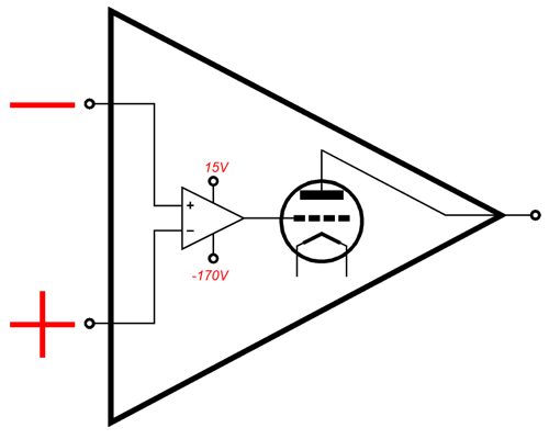
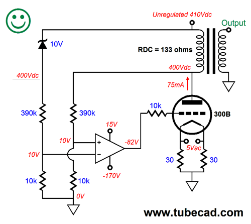
OpAmp-Based Input Stages Well, a few companies actually do make high-voltage OpAmps, such as Apex; and we can overcome this limitation with some clever design. Nonetheless, let's start with a simple—albeit a bit unrealistic—example: a two-stage, hybrid, single-ended power amplifier. Unrealistic? The OpAmp in this example sees a differential of 185 volts from its negative power-supply pin to its positive power-supply pin, which certainly counts as unrelealistic. Let's ignore this, however, and examine the rest of the circuit.
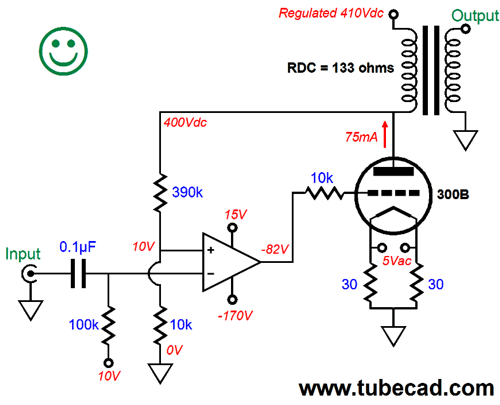
The input is capacitor coupled and a +10V bias voltage is applied at the OpAmp's inverting input via the 100k resistor. Due to the phase inversion produced by the 300B output tube being configured as a grounded-cathode amplifier, the OpAmp's inverting input is used; thus, effectively the OpAmp's inverting input becomes a non-inverting input, while the OpAmp's normally non-inverting input becomes the inverting input. The OpAmp's output DC couples to the 300B's grid via the 10k grid-stopper resistor. From the 300B's plate, a two-resistor negative feedback extends down to ground. The negative feedback loop works to establish an equal voltage on the OpAmp's two inputs at all times. This results in a fixed gain and low output impedance at the 300B's plate. Moreover, it greatly reduces the distortion at the plate, as the plate is the now effectively the output of this large hybrid OpAmp. In other words, the negative feedback loop does not include the output transformer. This is an important detail, as we will see later on. But for right now, we are in Happy Land; thus the happy face. One feature about which to be happy is the auto-biasing of the output tube, which results from the negative feedback and the 10V of bias voltage at the OpAmp's input. Once again, the OpAmp does all it can to maintain the exact same voltage at each of its two inputs, which means that it will try to force the 300B's plate voltage to exactly 400Vdc, as the two-resistor voltage divider that constitutes its negative feedback from the plate can only establish +10V with a plate voltage of 400Vdc. Since the regulated B+ connection delivers 410Vdc and since the output transformer primary's DCR (DC resistance) equals 133 ohms, the current flow through the DCR must equal 75mA, as 10V/133-ohms equals 75mA. In other words, auto-bias. As the output tube ages or is replaced, the same 75mA of idle current will obtain. Like Disneyland and Fantasy Island, Happy Land is a great place to visit, but no one really lives there. Here in Reality Land, things get tough, plenty fast. For example, very few power amplifiers, either solid-state or tube-based, enjoy a regulated B+ for the output devices. Sure, some are lucky enough to use high-voltage regulators for the input and driver stages, while others use some form of AC-only regulation on the B+ connection to the output stage, wherein ripple is scrubbed away, but no attempt is made to maintain a fixed DC output voltage. Why not? Harsh reality. The wall socket does not put out a fixed AC voltage, so a regulator must be able to contend with brown-outs and over voltages. Let's be forgiving and allow for only 10% slumps and 10% swells of the nominal wall voltage. Thus, the raw DC power supply behind the high-voltage regulator would see its raw DC fall by 10% or rise by 10%. Now, let's assume that a 410V regulator requires 40V of headroom, so the raw DC power supply voltage would be 450Vdc. If we reduce this voltage by 10%, we end up with 405Vdc, which, obviously enough, is not enough to deliver the required 410Vdc of output voltage. If we increase the 450Vdc voltage by 10%, we end up with 495Vdc, which means that the high-voltage pass device would have to handle the increased dissipation due to the more than doubling of the voltage drop across the pass device. Yet, in order to overcome the 10% droops in wall voltage, we will have to run a nominal 500Vdc of raw power supply voltage, 100%/90% against 450V equals 500Vdc. In other words, with a 90% of the normal wall voltage available, we still get 450Vdc of raw power supply voltage. And we have just been warming up, as not only is the wall voltage poorly regulated, the power transformer adds its poor regulation, which with high-voltage transformers can easily be 25%. What is transformer regulation? It is the measure of the ratio between the secondary's AC output voltage with and without a load. Some low voltage toroidal power transformer run 2% to 5% regulation figures, but most high-voltage power transformers, particularly those that use I & E laminations, run regulation figures closer to 20% to 40%. Assuming just a regulation figure of 25%, the 500V power transformer will put out 625Vdc with no load, such as when the tubes are cold and not conducting, which means that we can forget using 560V power-supply capacitors. In fact, we must account for a possible 10% over-voltage from the wall socket, so the 625Vdc can become 687Vdc. So much for breezily regulating the B+ voltage for the output stage of a tube power amplifier. In other words, the 410Vdc will not be regulated in Reality Land. The result is that the nominal 410V B+ voltage will vary with the wall voltage. Is this a big deal? Sure it is.
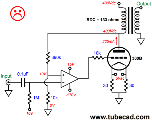
Here is small example: say the wall voltage climbs by only 5%, which it can easily do by just moving to another part of your town or from moving from the ground floor to the 20th floor of an old apartment building. The B+ voltage climbs to 430Vdc, just 20V more, but the output tube dissipation goes up by threefold, from 30W to 90W.
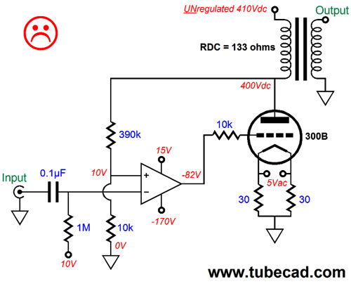
In addition, the unregulated power supply will not offer the regulator's clean, ripple-free voltage, which will become a much bigger problem due to the negative feedback loop. The OpAmp will strive to keep the output at the plate absolutely noise free, so the output transformer primary will see no ripple at the plate end and all the ripple at the B+ connection. Not good. The output transformer will treat the ripple as signal that must be transferred to the secondary and your loudspeaker. Now, you can see why so many prefer virtual reality to real reality.
But do not despair; like any good magician, I have many tricks up my sleeve.
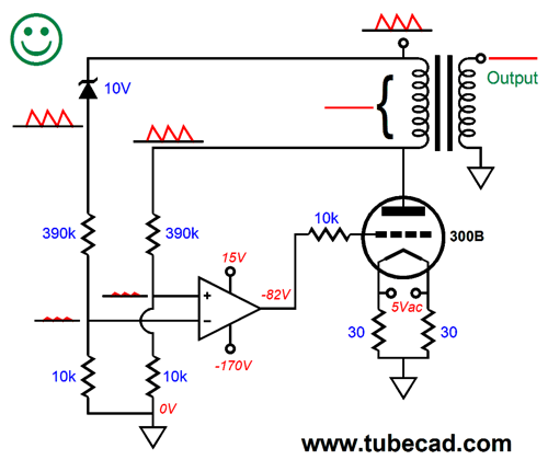
What we need to do is find a way to measure the DC voltage drop across the output transformer primary at idle, which means we have to inform the OpAmp what the B+ voltage is. Below, we see a pair of two-resistor voltage dividers and an added 10V zener diode. The zener diode creates a reference voltage that the OpAmp uses to maintain fixed 10V voltage drop across the transformer primary, as that is the only way that the OpAmp can see equal voltages on its two inputs.
Well, how well does this auto-bias trick work at eliminating power-supply noise from the output? Extremely well. Think about it: the power-supply noise is just fast moving B+ voltage variations. Now it might seem paradoxical that we want the 300B plate to see all of the power-supply noise that the B+ holds, but that is only because we tend to think only in terms of ground reference. But from the perspective of the output transformer primary, if it sees no delta, no difference between its leads, then it will ignore whatever common-mode signal is present. Another way of putting it is that the transformer's primary is B+ referenced, not ground referenced.
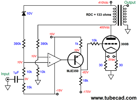
Okay, now that we have taken our baby steps, we can make the adult leap forward to an actually usable power amplifier.
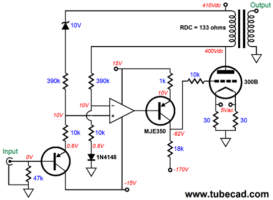
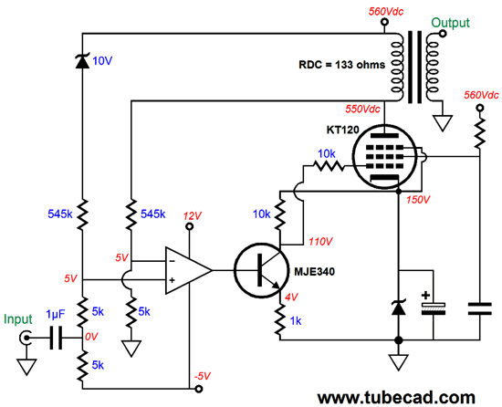
We have given the OpAmp +/-15V power-supply rails and added a high-voltage PNP transistor, an MJE350. Because the transistor inverts its input signal, we must invert the OpAmp inputs, so that the inverting input is used as the inverting input for the entire power amplifier. The amplifier's input signal is capacitor coupled with the 1µF capacitor and the two-resistor voltage divider feeds the slightly attenuated input signal to the OpAmp's non-inverting input. The assumption here is that the input signal source will offer a low input impedance, so that the two-resistor voltage divider can do its magic. If a 100k volume potentiometer is used in front of the coupling capacitor, then the deal is off, as the potentiometer's high output impedance, as much as 25k with a 100k potentiometer, will undo the AC voltage division. (The DC voltage division will still obtain, as will the auto-bias functionality.) If a volume potentiometer or high-impedance signal source must be used, then the following workaround will offer the required low input impedance for the two-resistor voltage divider.
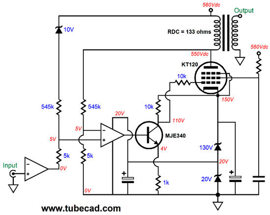
The added 1N4148 signal diode was needed to compensate for the 0.6V voltage drop from the transistor's base to its emitter. This hybrid power amplifier uses a negative power-supply rail, which we may not have readily available, so the following design uses a monopole high-voltage power supply.
The B+ voltage has been upped to 560Vdc, which is a convenient voltage, as 400Vac rectifies up to 560Vdc. The 150V zener establishes the DC voltage window within which the NPN transistor works. This is still a fixed bias arrangement, as the KT120's grid attaches to the (110V) collector, not a grid resistor to ground. The KT120 is operated as a pentode, which would normally present a high plate impedance; but with the negative feedback loop in place, the output impedance at the plate will be plenty low. Once again, the auto-bias feature ensures that at idle, 10V of voltage will drop across the output transformer primary. The feedback resistors set a gain of (545k + 5k)/5k or 110, which means that about 3Vpk of input signal will be needed to bring the amplifier to full output. (Remember that the input two-resistor voltage divider's slight attenuation must be factored in the equations.) As I came up with this design, my first impression was that this would make a fine music power amplifier. This then led to my thinking that an extra OpAmp would not be out of place in such an amplifiers either a guitar or microphone input would require lots more gain, which an extra OpAmp could easily provide.
Note how we are deriving the OpAmp power supply from the 20V zener diode. By using two 15V zeners, we could have created an artificial ground for the OpAmps and given the OpAmps +/-15Vdc power-supply rails. But I think that I will stop right here, as there is plenty to feast on already.
Next Time
User Guides for GlassWare Software
For those of you who still have old computers running Windows XP (32-bit) or any other Windows 32-bit OS, I have setup the download availability of my old old standards: Tube CAD, SE Amp CAD, and Audio Gadgets. The downloads are at the GlassWare-Yahoo store and the price is only $9.95 for each program. http://glass-ware.stores.yahoo.net/adsoffromgla.html So many have asked that I had to do it. WARNING: THESE THREE PROGRAMS WILL NOT RUN UNDER VISTA 64-Bit or WINDOWS 7 & 8 or any other 64-bit OS. I do plan on remaking all of these programs into 64-bit versions, but it will be a huge ordeal, as programming requires vast chunks of noise-free time, something very rare with children running about. Ideally, I would love to come out with versions that run on iPads and Android-OS tablets.
//JRB
|
|
I know that some readers wish to avoid Patreon, so here is a PayPal button instead. Thanks. John Broskie
Kit User Guide PDFs
Only $12.95 TCJ My-Stock DB
Version 2 Improvements *User definable Download or CD ROM www.glass-ware.com |
||


| www.tubecad.com Copyright © 1999-2011 GlassWare All Rights Reserved |