| John Broskie's Guide to Tube Circuit Analysis & Design |
| 22 February 2015 Sound Advice:
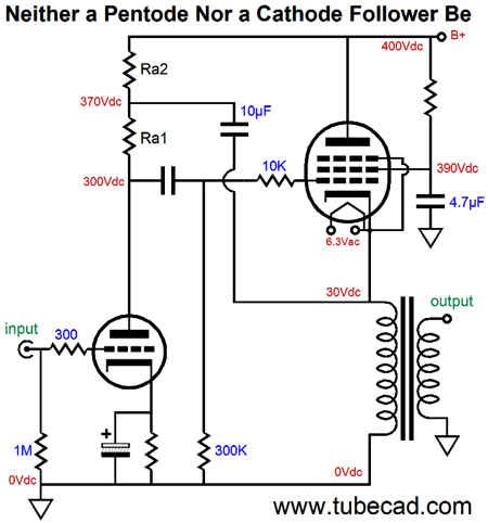
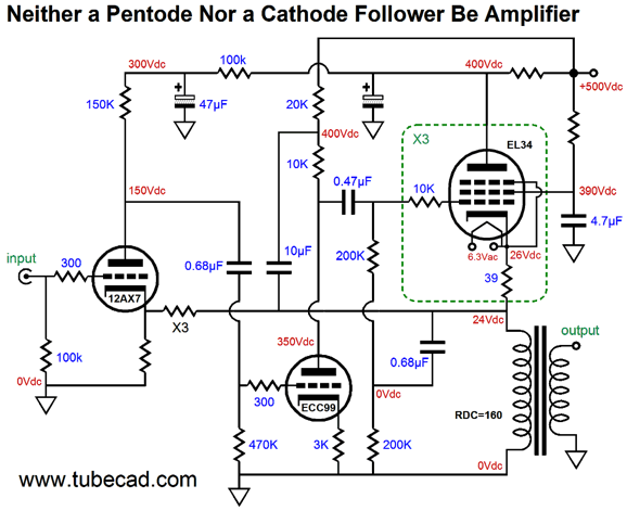
Neither a Pentode Nor a Cathode Follower Be Amplifier
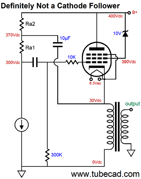
Or is possible that your eyes and my words are both half right? If so, which half is right? Let's start with the question over whether the output tube operates as a triode or a pentode. In true pentode operation, grid number 2 is at a fixed voltage relative to the cathode, even when the pentode is used a cathode follower circuit.
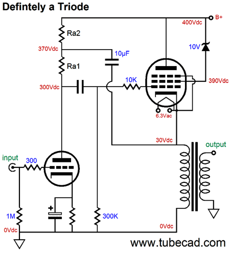
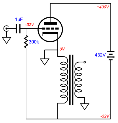
As the cathode swings up and down in voltage, so, too, will the grid-2 voltage, for the large electrolytic capacitor maintains a fairly fixed voltage, much as a battery would. In the neither-a-pentode-nor-a-cathode-follower-be (NPNCFB) circuit the cathode swings hugely up and down, but grid-2 remains 10 volts lower in voltage than the plate. In fact, we could replace the resistor and capacitor with a single 10V zener, as shown below.
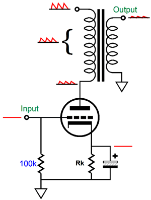
This pentode also sees a fixed 10V difference between plate and grid-2 and it obviously is triode-connected. Well, why not use the zener instead? The resistor and capacitor offer an added advantage in that the RC-filter action they impose improves the PSRR of the output tube. The second question is the output tube working as a cathode follower or a grounded-cathode amplifier? Well, let's begin with an output stage (OPS) that is unambiguously a cathode follower.
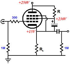
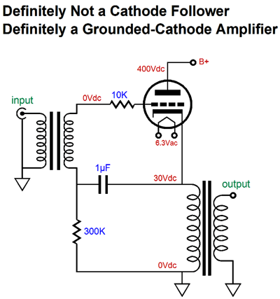
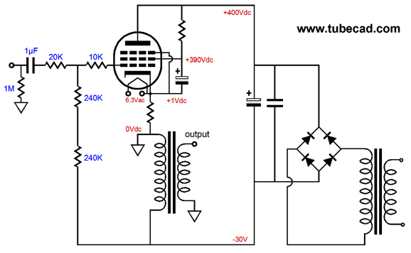
The output tube receives its input signal from the input tube and no capacitor connects the output tube's cathode to the input stage. A cathode follower plain and simple. So what does the 10µF capacitor connects the output tube's cathode to the input stage do in the previous schematic? In short, this bootstrap capacitor undoes the cathode follower functioning, making the output tube function more like a grounded-cathode amplifier. The following circuit make this clear. If we replace the input tube with a constant-current source, then the output impedance at the output tube's cathode is not the rp/(mu + 1) that a cathode follower would deliver, but just its plate resistance, its rp, which is a grounded-cathode amplifier would present.
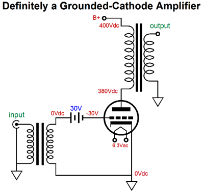
If the current source departed from constant current flow to a modulated flow, a flow with music signal superimposed upon its idle flow, we would see the output stage swing hugely up and down, as the output tube would see a varying input signal that would prompt its current conduction to vary in response, developing a varying voltage drop across the primary impedance. But wait a second, John; the transformer attaches to ground, not the B+ voltage, so how can it possibly function as a grounded-cathode amplifier, when its cathode is not grounded? Fair question. The answer lies in the where the triode sees its input signal reference, not the power supply ground. Here a simple example of an inverted grounded-cathode amplifier.
An isolation transformer is used, as requires no connection to "ground," floating with the output signal present at the cathode. The battery provides the needed negative bias voltage to set the desired idle current flow. If you want to use the output transformer's primary DCR as the cathode-bias resistance, then the following variation can be used.
Understand that the triode cannot tell a difference between the above two configurations and the following, as it sees identical grid-to-cathode and cathode-to-plate voltages and the same Miller-effect capacitances. (Because the bottom end of the output transformer is grounded, the phase is no longer inverted, which is not important here, but will become important later.)
All of these grounded-cathode amplifiers deliver the same gain, distortion, and output impedance, in spite of where the output transformer is situated.
A circuit is a circle of current flow. A single triode or resistor or battery are not circuits, as no circle of current flows. Once we have created a circuit, we can alter the relative positions within the circuit, as long as we abide by the rules; for example, diodes must be forward biased to conduct current. And where we decide to place the ground, the signal reference is pretty much unbound, in spite of most tube circuits using the power-supply negative as ground. In the following example, we see an inverted grounded-cathode amplifier, which uses the output transformer's DCR as a cathode-bias resistance. (A free lunch of sorts.) Note how the circle of current still flows just as it would within a more conventional amplifier, whose output transformer appeared between the B+ and the triode's plate.
The key feature of the above circuit is that the power supply is not grounded, so it can move freely with the output signal developed across the output transformer primary and swing plate voltage. If an extra ground were added, so the power supply was "grounded properly," then there could be neither amplification nor correct biasing of the triode. With the ground placed at the cathode, the amplifier amplifies; with the ground placed at the bottom of the primary, the buffer follows. From this simple circuit, we can move to this slightly more elaborate one.
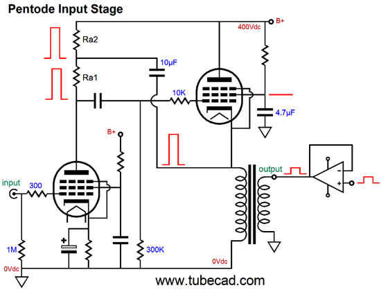
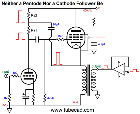
The output tube functions as a pentode, not a triode. The grid resistor has been replaced by two resistors in series and a 20k resistor has been added. We now have a negative feedback loop. The output signal present at the bottom of the output transformer primary is in inverted phase relative to the input signal, just as we would expect from a grounded-cathode amplifier. In other words, the grid resistor(s) now functions both as a grid resistor and as feedback-loop resistor. If we replace the 20k resistor with a 480k resistor, the amplifier's gain falls to unity. Okay, let's return to our original circuit. Since constant-current sources are rather abstract devices, lets replace it with an active device that offers a very high output impedance, such as a MOSFET or FET or pentode. Now imagine that we attach a power amplifier to the secondary and apply a single positive voltage pulse.
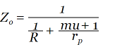
The pulse gets magnified by the winding ratio between primary and secondary. The much bigger pulse is then relayed by the 10µF bootstrap capacitor to the top of plate resistor Ra1, which in in turn relays the entire pulse to the output tube's grid. The resistance the output tube can offer is its plate resistance, as its cathode and grid see the same upward swing in voltage. Clearly, this is not what a cathode follower would do, as a cathode follower's output impedance is equal to:
or, roughly, rp/(mu + 1). Triodes, unlike pentodes, exhibit a low plate resistance, which can be very low indeed. For example, a 6AS7 offers a low plate resistance of about 280 ohms, while a triode-connected EL34 offers about 1.2k of plate resistance. So what happens when the positive pulse is forced through the amplifier with a triode input tube, particularly a triode with a capacitor-bypassed cathode resistor?
The result is that the grid no longer sees the fully magnified pulse, but only a portion of it. The input triode's plate resistance and resistor Ra1 define a two-resistor voltage divider. This reduced grid pulse creates negative feedback, so the output triode can offer more than just its rp in opposition to the pulse, as the voltage difference in grid-to-cathode voltage prompts a larger change in current conduction by the output tube. If the pulse were reduced by 50%, the output stage would mimic a Circlotron in many respects.
The Logic Behind the NPNCFB Amplifier
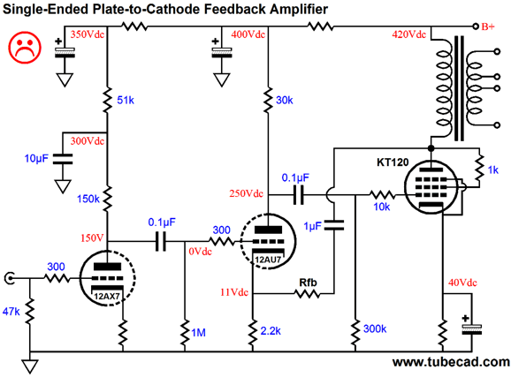
And if we try to get clever and add a negative feedback loop from the plate to the driver tube, we make the problem worse, as we have effectively reduced the output tube's plate resistance, which in turn gives the primary a larger share of the power-supply noise, making the PSRR worse, not better.
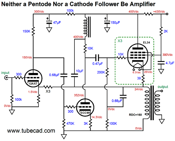
But if we move the output transformer to the bottom of the output tube, we no longer encounter the problem of the feedback loop worsening the PSRR, as the negative feedback reduces the amount of power-supply noise that appears across the primary. Since the NPNCFB topology does not invert its input signal's phase at its output, the negative feedback loop can no longer be returned to the driver tube; instead, it must travel back to the input tube's cathode. (Actually, we could use an inverting amplifier feedback loop that would connect to the driver tube's grid, rather than its cathode.)
The feedback resistor is marked by X3, which signifies that three equal-valued resistors are to be used in series. Why? Since the output tube's cathode will swing huge voltages, it is safer to use three resistors in series; in addition, it reduces the amount of voltage-induced distortion that the resistors can give rise to. The inductor is there to give the driver stage more B+ voltage to play with and to reduce the parallel loading of the primary. Since finding audio-grade chokes is difficult, I would probably forgo its use and use the following arrangement instead.
A 500Vdc power supply is used, which is easy to build, as 800Vac CT power transformers are common (and 400Vac rectifies up to about 560Vdc, which tube rectifiers and chokes can easily lower to 500Vdc). In all the NPNCFB designs, the output tubes require their own heater winding, which must be referenced to the top of the output transformer primary. I would use an 18Vdc power supply and place all three EL34 heaters in series. Why? This arrangement offers some added safety, as it requires that all three EL34s be in their sockets before completing the heater circuit. Why is that safer? Imagine that only one EL34 is in place; the 200 ohms of resistance between its cathode and ground is insufficient to properly bias the tube, so the lone EL34 will egregiously over heat. With the 18Vdc power supply and the missing two EL34s this is not possible; much like a Christmas-tree string of lights, all the tubes must be in their sockets for any of them to heat up.
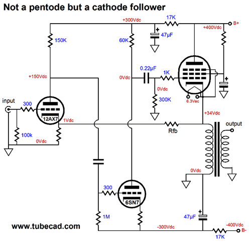
A True Cathode-Follower Power Amplifier
This is a huge problem for the driver stage, particularly when it shares the same B+ voltage as the cathode-follower output stage. In the NPNCFB design, the bootstrap capacitor allowed the driver stage to develop output swing in excess of the B+ voltage, but the bootstrap capacitor also undermined the cathode-follower operation. We could use two B+ voltages, say 400Vdc for the input and cathode-follower output stage, and 800Vdc for the driver stage. My preference, however, would be to use a bipolar power supply. Why? A 400Vdc power-supply rail, whether it be positive or negative, is one fourth as dangerous as an 800Vdc power supply, as we must square the voltage to determine its wallop; thus, twice the voltage, four times the wallop. (This is much like a bullet's velocity, as twice the speed, four times the foot-pounds of energy.)
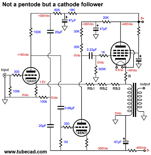
The 12AX7-based input stage will develop a gain of about 50 (+34dB), while the 6SN7-based driver stage will present a gain of about 10 (+20dB), creating a final gain of about 500 (+54dB), which would allow for about 6dB of negative feedback to be applied. (Of course, we could forgo the negative feedback loop, as the cathode-follower OPS already offers low distortion and low Zo.) The following schematic shows the above circuit fleshed out.
The aim here is to "ground" the input stage's B+ connection not to ground, but to the negative power-supply rail. Why? The 6SN7's cathode is referenced to the negative rail, so its grid should see the same amount of rail noise, so that the noise can null at its plate. If the input stage saw a perfectly noise-free B+ connection, the PSRR would worsen, not improve. It's all relative, you see. The better choice might be to use a pentode, such as the EF86, in place of the 12AX7. Or, perhaps, better still, we would replace the single input triode with a cascode made up of two triodes. Both the pentode and cascode offer a very high plate impedance indeed, which means that more of the negative power-supply rail noise would be superimposed upon their output signal, thereby increasing the PSRR of the amplifier. See blog numbers 248, blog 49, blog 50, blog 53, and blog 300 for more details on cathode-follower output stages.
A Hybrid Source-Follower Amplifier
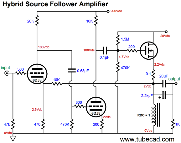
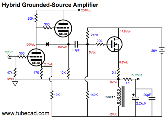
If the inductor exhibited zero DC resistance (DCR), we could forgo the output coupling capacitors. But as that is unlikely, the capacitors are needed to prevent the DC offset from damaging the speaker voicecoil. How much inductance should the inductor offer? Much less than you might imagine, as just 100mH will give us bandwidth down to 10Hz. (With the feedback loop in place, even lower frequencies can be reproduced.) The two stages of gain create a final gain of about 250, which means that plenty of negative feedback can be applied, as the amplifier only needs a gain of about 20 to be driven to full output with a 1Vpk input signal. If less feedback is desired, a 12AU7 or 12BH7 could be used. Since the idle current in this example is 2A, the peak output current is also 2A, which means that into an 8-ohm load, the output stage can deliver 16 watts of power (average power, not peak, which would be twice as high and misleading). If the MOSFET's B+ voltage had been 30V and its idle current 3A, the power output would equal 3²Rload/2, or 36W. One last circuit: a hybrid grounded-source amplifier. This design uses the power MOSFET in a grounded-source configuration, so it provides gain and phase inversion.
Note that the ground falls at the top of the inductor, which undoes the previous circuit's source-follower action. Also note the floating 20V power supply. As the MOSFET's current conduction varies, the inductor and floating power supply allow the output to swing up and down. The 10k feedback resistor returns a portion of the output signal to the input triode's cathode, completing the negative feedback loop. The second triode provides the low output impedance and current needed to drive the MOSFET to full output. Very Zen-like.
Next Time
User Guides for GlassWare Software Since I am still getting e-mail asking how to buy these GlassWare software programs:
For those of you who still have old computers running Windows XP (32-bit) or any other Windows 32-bit OS, I have setup the download availability of my old old standards: Tube CAD, SE Amp CAD, and Audio Gadgets. The downloads are at the GlassWare-Yahoo store and the price is only $9.95 for each program. http://glass-ware.stores.yahoo.net/adsoffromgla.html So many have asked that I had to do it. WARNING: THESE THREE PROGRAMS WILL NOT RUN UNDER VISTA 64-Bit or WINDOWS 7 & 8 or any other 64-bit OS. I do plan on remaking all of these programs into 64-bit versions, but it will be a huge ordeal, as programming requires vast chunks of noise-free time, something very rare with children running about. Ideally, I would love to come out with versions that run on iPads and Android-OS tablets.
//JRB |
E-mail from GlassWare Customers
High-quality, double-sided, extra thick, 2-oz traces, plated-through holes, dual sets of resistor pads and pads for two coupling capacitors. Stereo and mono, octal and 9-pin printed circuit boards available.  Aikido PCBs for as little as $24 http://glass-ware.stores.yahoo.net/
Support the Tube CAD Journal & get an extremely powerful push-pull tube-amplifier simulator for TCJ Push-Pull Calculator
TCJ PPC Version 2 Improvements Rebuilt simulation engine *User definable
Download or CD ROM For more information, please visit our Web site : To purchase, please visit our Yahoo Store: |
|||


| www.tubecad.com Copyright © 1999-2015 GlassWare All Rights Reserved |