| John Broskie's Guide to Tube Circuit Analysis & Design |
30 August 2015 Aikido Grounded-Cathode Amplifier
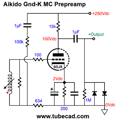
Above, we see an MC pre-preamplifier employing the Aikido noise-null technique. One 6DJ8 triode and a few parts is all that are needed. Simple, very simple, yet effective. But what about applying this same Aikido technique to a line-stage amplifier, whose input signals are not floating, but are all grounded-referenced; is that possible? Would I pose this question if the answer was no? Yes, I would.
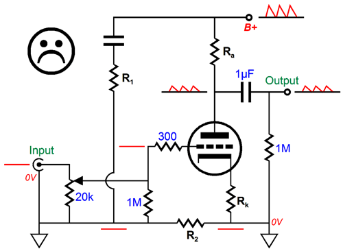
Note how the "grounded" input means that no power-supply noise can be injected into the grounded-cathode amplifier's grid, which means that no PSRR enhancement obtains. Of course, if the input signal is floating, then this Aikido technique can be put in place. If mono playback were still popular, this might just work (if the signal ground were not tied to the house ground); but with stereo playback the two channels always share a common ground connection, i.e. no floating. In every CD player, DAC, tuner, tape player, phono stage there is one common signal ground. Is there no workaround? Indeed there is: a 1:1 signal transformer.
The transformer breaks the ground connection between the signal source and the grounded-cathode amplifier, so we can effectively create a floating input signal out of a normally grounded one. In fact, the transformer's primary also allows us to break its connection to the grounded-cathode amplifier's signal ground. Note how the transformer's secondary is constantly loaded by the 20k volume control and how both ends of the potentiometer carries an equal amount of power-supply noise. Thus, regardless of the volume control position, the same amount of power-supply noise is injected into the grid, which results in a constantly high PSRR. Without this injection of ripple, the grounded-cathode amplifier's PSRR is relatively poor, ranging from -6dB to -12dB, depending on the plate and cathode resistor values and whether the cathode resistor is bypassed or not. Also note that secondary's phase can readily be flipped at the transformer secondary, so no phase inversion results at the output of the line-stage amplifier. (Of course, we have no control over how the phase got recorded in the first place on the LP or CD.) The 1M grid resistor keeps us safe, should the volume control monetarily lose scraper contact. Voltage-divider resistors R1 & R2 must be adjusted for each grounded-cathode amplifier configuration, such as different triode types and plate and cathode resistor values. Cute, John, very cute, but don't you get it: signal transformers suck? Do they? How so? I have done a complete 180 on the input transformer, as I, too, used to damn them instinctively. No more. A good signal transformer can be a blessing, as it can solve grounding problems that no other means can approach. In addition, it offers DC isolation and its limited frequency bandwidth may prove a godsend with many power amplifiers. Think about it: do you really want to amplify input DC offset voltages and radio frequencies? Because it offers DC isolation, the input transformer allows us to make the following variation, which uses a high-voltage, bipolar power supply.
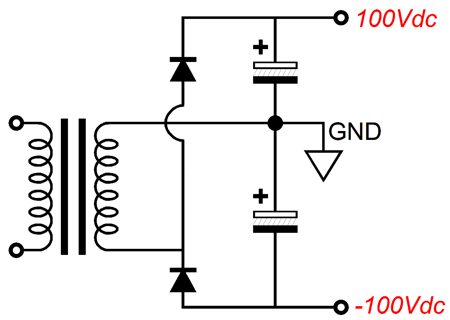
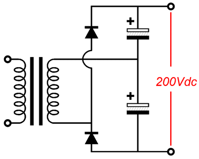
The triode's cathode sits down near the -100V power-supply rail, while its plate sits near ground potential. Most importantly, this topology naturally creates an Aikido power-supply noise null at its output, assuming that the both negative and positive power-supply rails share an identical amount of out-of-phase ripple. This assumption is a fair one, as long as this goal is kept in mind. If we do not keep it in mind, the mirrored symmetry will be compromised. For example, a voltage doubler circuit would prove a bad choice.
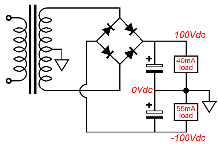
This power supply does not offer anti-phase ripple, as one capacitor charges up at a time, not both at once. The result is that each power-supply rail develops 60Hz (or 50Hz) ripple, not the usual 120Hz ripple. On the other hand, if we place the ground connection at either the bottom or top, then the two ripples add together, thereby creating 120Hz ripple. In addition, if one rail sees a bigger current draw, the balance between rail ripples will diminish.
The plate and cathode resistor values must be selected carefully. The formula is an easy one:
Since the input transformer's secondary is truly floating, we can rearrange the parts to create an inverted amplifier, as shown below.
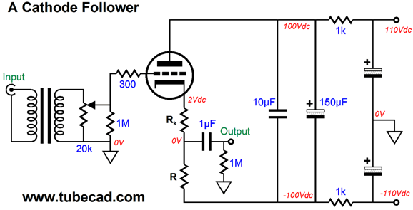
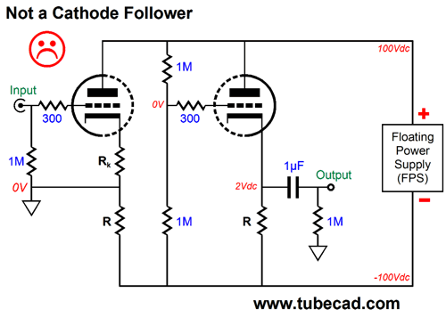
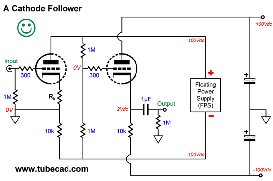
The inverted amplifier is an old topology that was, long ago, often used in carbon-microphone preamps, electronic instruments, and Geiger counters. It is a grounded-cathode amplifier with a floating input signal, which allows us to move the plate load down to below the cathode resistor. Remember, a circuit is a current circle, so we can move components around the circle, as long as no unidirectional devices get reversed biased. The inverted amplifier's gain, distortion, PSRR, and output impedance are identical to the conventional grounded-cathode amplifier, save for one difference: no phase inversion. A positive input voltage causes a positive output swing. But John, it sure looks like a cathode follower, so why isn't a cathode follower? What makes a cathode follower a cathode follower is where the input signal's voltage reference is taken—where it is grounded, in other words. For example, the following topology is a cathode follower, because the input signal's ground is indeed grounded, and not left floating.
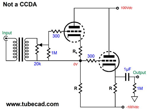
No signal gain and a low output impedance and distortion figure result. Okay, why not add a cathode follower to the inverted amplifier, thereby gaining both gain and low output impedance? We can, as we see below.
The input signal is floating, so the first stage develops gain and the second stage sees a grounded-referenced input signal, so it functions as a cathode follower. Note how no phase inversion occurs. This is important, as the entire circuit does not behave as CCDA (Constant-Current-Draw Amplifier), as both the input and output stages work in current phase. This is a tad unfortunate, as the power supply will have to be more robust, as it will have to contend with a varying current draw; in addition, the distortion will tend to compound, rather than average down, as both triodes will bend in the same direction. A triode more easily turns on than it turns off, so it creates a second harmonic distortion as it amplifies or buffers. By cascading the two current-in-phase stages, the distortion adds together. Do not panic. In a line-stage amplifier, this compounding distortion is not that big a deal, as the output signals are relatively small, both in current flow and voltage development. After almost two decades of reading e-mail from readers, I know that both input transformers and bipolar power supplies encounter strong opposition. Reasons are not hard to find. Good input transformers are expensive and rare. Bipolar power supplies usually entail solid-state rectifiers, forcing us to stray from the path of Pure-Tube Sound. Well, there is a way to forgo both.
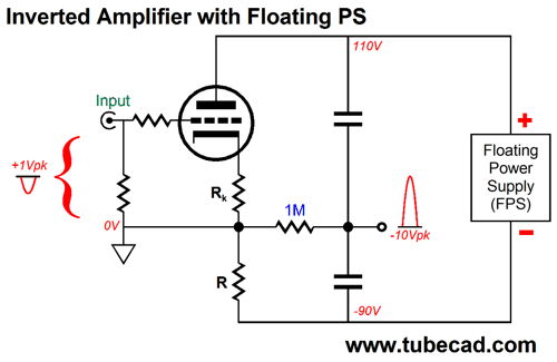
Inverted Amplifier with Floating Power Supply If we ground at the power supply's negative terminal, we get the usual ripple at the B+ connection. If we ground at the power supply's positive terminal, we get an inversion of the ripple at the B- connection. If we use a two-resistor voltage divider with equal valued resistors, and we attach ground at the connection between the two resistors, we get a floating power supply, not a grounded one. In addition, we halve the ripple, as half appears at the B+ and half at the B- connections. These two halved ripples are equal in amplitude, but out of phase with each other, which we can exploit.
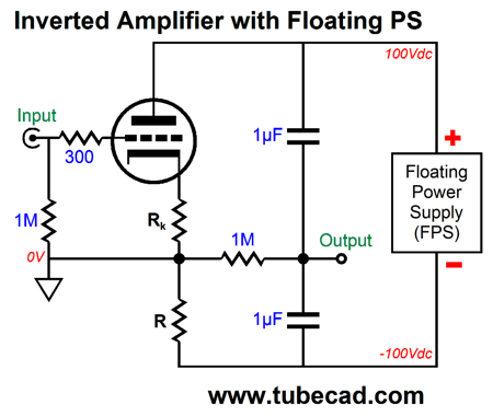
For example, in the following circuit, we see an inverting grounded-cathode amplifier, powered by a floating power supply. The power supply floats, as we placed "ground" at the the bottom of the cathode resistor.
Now, fasten your mental seat-belts. Remember that the triode has no idea what circuit it is in; all it "knows" are the voltage relationships between its cathode and grid, between its grid and plate, and between its cathode and plate. If we make the grid slightly more positive, then the triode will conduct more current. If we make the grid slightly less positive, then the triode will conduct less. Since al the current that flows through the triode also flows through the load resistor, R, the voltage drop across resistor R will vary with the varying current flow through the triode.
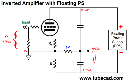
Above, we see a positive pulse applied to the grid, so the triode increases its current conduction, which in turn increases the voltage drop across both the cathode and load resistors, which will pull down the plate voltage, making the output deliver an amplified negative pulse. Note that both capacitors function as coupling capacitors and both see a fixed 100V differential.
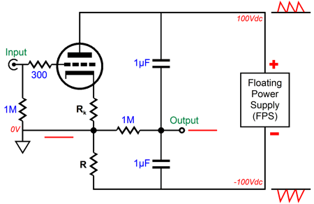
This time, we apply a negative pulse to the grid, so the triode decreases its current conduction, which decreases the voltage drop across both the cathode and load resistors, which will increase the plate voltage, making the output swing positively. If we had not used a floating power supply, but a grounded one, then the output would have not moved off 0V. What happens to the floating power supply's ripple? It nulls at the output, as the two coupling capacitors function as a 50% AC voltage divider, as (1 - 1)/2 = 0.
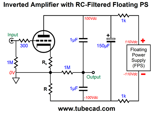
Note how the coupling capacitors also function as bypass capacitors for the floating power supply. Interesting. In the following schematic, we see the 150µF electrolytic capacitor bypassed by a 0.5µF (film or PIO) capacitor, as two 1µF capacitors in series equal 0.5µF.
Note that a stereo line-stage amplifier will require two floating power supplies, one for each channel. Nonetheless, this topology should arouse our attention, as it offer an easy way to achieve a single-triode Aikido PSRR move. With this topology, we can use the high-voltage voltage doubler circuit, as it is floating, not grounded.
Okay, no doubt some will immediately think that adding a cathode follower to the inverted amplifier is the next step. Not a good idea, alas.
It may look just like a cathode follower, but it isn't, as it does not offer a low output impedance. In fact, the added triode is not that active, behaving more like a plain resistance, rather than an active device that displays transconductance. On the other hand, if the power supply were grounded, then the added triode would function as a true cathode follower. We can add a second power supply, one that is grounded. The result is that the cathode follower functioning obtains.
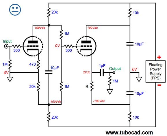
The added grounded power supply could be shared between two channels. Still, three power supplies is a bit much, as even having to assemble two floating power supplies is a pain. Well, we could use just one floating power supply, as the following circuit shows.
The three 10µF capacitors do the heavy lifting here, as they allow the input stage to function as a grounded-cathode amplifier and the second stage to function as a cathode follower. The floating power supply could be shared between two channels, although only one channel is shown. So where is the missing happy face? The problem with this topology is that the input triode is not just loaded by the 20k load resistor below it, but by the additional 15k of resistance in parallel with it, resulting in a little over 8.5k worth of load resistance. Is this a big problem? No, but it does mean less gain and more distortion. Is there a workaround? Yes, but it is complicated. We could use a constant-current source, a compliant-current source and two emitter (or source) followers to replace the top and bottom 20k and 10k resistors. Very complicated, in other words.
Next Time
User Guides for GlassWare Software Since I am still getting e-mail asking how to buy these GlassWare software programs:
For those of you who still have old computers running Windows XP (32-bit) or any other Windows 32-bit OS, I have setup the download availability of my old old standards: Tube CAD, SE Amp CAD, and Audio Gadgets. The downloads are at the GlassWare-Yahoo store and the price is only $9.95 for each program. http://glass-ware.stores.yahoo.net/adsoffromgla.html So many have asked that I had to do it. WARNING: THESE THREE PROGRAMS WILL NOT RUN UNDER VISTA 64-Bit or WINDOWS 7 & 8 or any other 64-bit OS. One day, I do plan on remaking all of these programs into 64-bit versions, but it will be a huge ordeal, as programming requires vast chunks of noise-free time, something very rare with children running about. Ideally, I would love to come out with versions that run on iPads and Android-OS tablets.
//JRB |
Kit User Guide PDFs
And
High-quality, double-sided, extra thick, 2-oz traces, plated-through holes, dual sets of resistor pads and pads for two coupling capacitors. Stereo and mono, octal and 9-pin printed circuit boards available.
Designed by John Broskie & Made in USA Aikido PCBs for as little as $24 http://glass-ware.stores.yahoo.net/
The Tube CAD Journal's first companion program, TCJ Filter Design lets you design a filter or crossover (passive, OpAmp or tube) without having to check out thick textbooks from the library and without having to breakout the scientific calculator. This program's goal is to provide a quick and easy display not only of the frequency response, but also of the resistor and capacitor values for a passive and active filters and crossovers. TCJ Filter Design is easy to use, but not lightweight, holding over 60 different filter topologies and up to four filter alignments: While the program's main concern is active filters, solid-state and tube, it also does passive filters. In fact, it can be used to calculate passive crossovers for use with speakers by entering 8 ohms as the terminating resistance. Click on the image below to see the full screen capture.
Tube crossovers are a major part of this program; both buffered and un-buffered tube based filters along with mono-polar and bipolar power supply topologies are covered. Available on a CD-ROM and a downloadable version (4 Megabytes). |
||


.png)


| www.tubecad.com Copyright © 1999-2015 GlassWare All Rights Reserved |