| John Broskie's Guide to Tube Circuit Analysis & Design |
06 December 2015
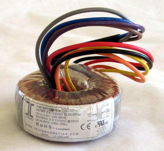
New GlassWare Product: Triad B+ Transformer
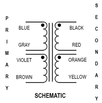
The two secondaries allow two rectified B+ voltages to be created, either 165Vdc @ 100mA or 330Vdc @ 50mA. The two primaries allow this transformer's use with either 120Vac or 230-240Vac wall AC voltages.
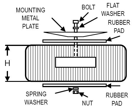
This toroid is a great match with the PS-1 regulator, along with the TA050-12 12Vac toroid for the heater regulator portion of the PS-1. I should know, as I have used many of these toroids in the past. It could also be used with PS-3 or PS-15 or PS-18. It would also work well with the ACF-2 PCBs. Because I charge a flat-rate of shipping, you will not be penalized for its high weight (1.102 lbs). This high-voltage toroid comes with the mounting hardware and large rubber washer and is available now that the GlassWare store and costs only $22. Here is its data sheet.
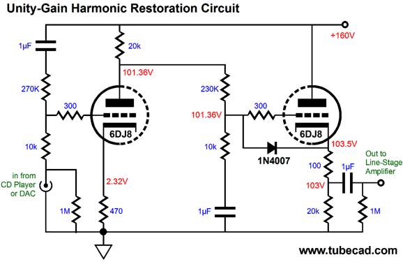
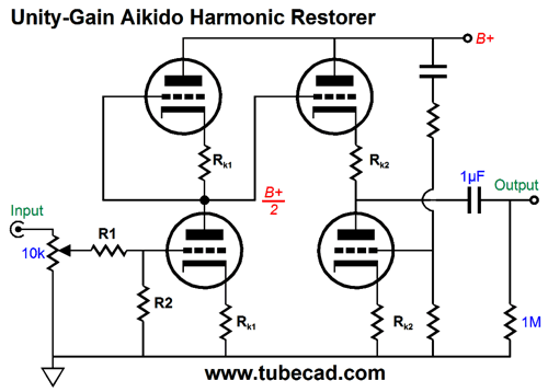
Unity-Gain Aikido Harmonic Restorer My last contribution on this topic was in blog number 316. Here is an example circuit from that post.
This circuit uses only two triodes and offers excellent performance, but it cannot be used with an input volume control. Well, my new elaboration on this theme can be used with a volume potentiometer. Its design was prompted by a small coincidence: the same-day delivery an e-mail and an ad that both concerned harmonic restoration. The e-mail (from Rodrigo) asked if by adding a two-resistor attenuator in front of the Aikido circuit, could not the Aikido gain stage be converted into a harmonic restorer circuit. His reasoning was that since most DACs and CD players, tuners, phono stages already put out sufficient signal to drive most power amplifiers to full output, why not reduce their output signal by the inverse of the Aikido's gain, so unity gain results—but with the addition of the harmonic distortion the Aikido imposes, making for a fuller, richer sound, while still retaining the Aikido's high PSRR and low output impedance.
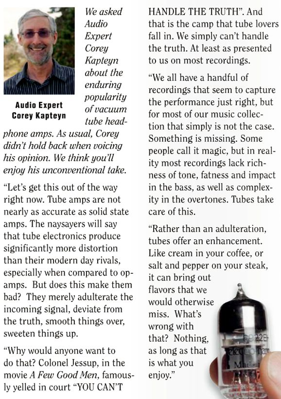
The above circuit is what Rodrigo had in mind. Resistors R1 & R2 define a fixed signal attenuator. If the Aikido's gain is 10, then the two resistors should only let 1/10th of the signal pass. For example, R1 could equal 90k; and R2, 10k. My first thought was that he failed to appreciate how little distortion the Aikido gain stage would produce, robbing his ear of the riper sound it desires. The second prompt came from my reading the Audio Advisor's latest flyer, which had arrived the same day as Rodrigo's e-mail. Here is what I saw on page 14.
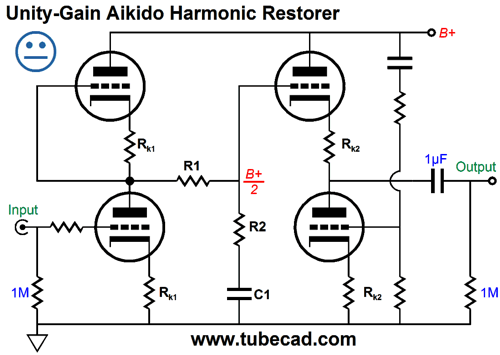
My first impression was not all that charitable. If nothing else, I always get nervous when the word "Truth" is mentioned by anyone and I usually think "sterile" and "eviscerated" when I see in the audio press the word "accurate." But as I let Mr. Kapteyn's remarks settle, I grew more favorably disposed to them. Indeed, I endorse them. I then wrote back to Rodrigo with my remake of the Aikido harmonic restorer, which moved the two-resistor attenuator inside the Aikido, rather than placing it in front of it.
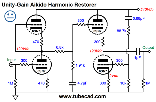
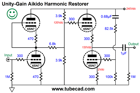
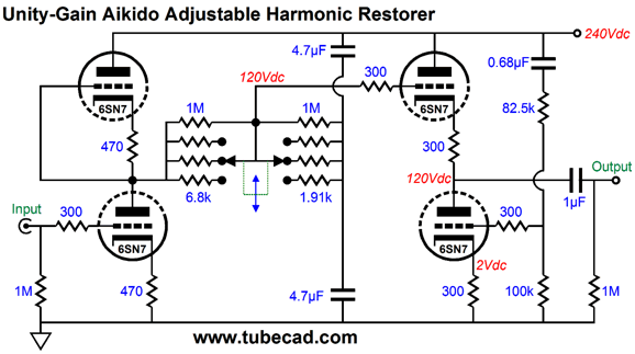
The logic is simple: the bigger the voltage swings, the more harmonic distortion. Instead of presenting the Aikido's input with 0.1V of signal and let it be amplified up to 1V, the above Aikido-based harmonic restorer circuit sees the full 1V of input signal, which it then amplifies to 10V before it is attenuated down to 1V at its output. Because the audio signal is reduced by 10, the power-supply noise is attenuated to 1/20th at the input grid of the Aikido cathode follower, we must alter the ratio of power-supply noise that is injected into the grid of the bottom triode in the Aikido cathode follower. Here is the same circuit with the part values and voltages filled in. (A 6SN7 is shown, but a 12SN7 or 12SX7 or 6CG7 could be used instead. Indeed, just about any dual-triode tube could be used, if the resistor values are adjusted.)
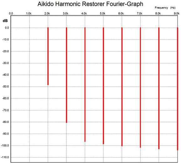
Note the low voltage divider resistor values, only 6.8 and 1.91k. Why so low? The low resistance increases the distortion from the input stage, bring the distortion up to almost 1% at the output.
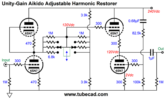
The graph shows the harmonic content of 1Vpk at 1kHz. Note the strong 2nd harmonic and the beautifully single-ended nature of the harmonic structure. So, are we done? No. Thus, the neutral, rather than the smiling face icon. As I see it the 4.7µF is a pain, as is the math required to set the ratio of power-supply noise that is injected into the grid of the bottom triode in the Aikido cathode follower. But how could I get rid of the 4.7µF capacitor? If it were shorted, the Aikido cathode follower stage would not see the desired DC voltage at its input. Well, we can lose the capacitor by adding an extra resistor.
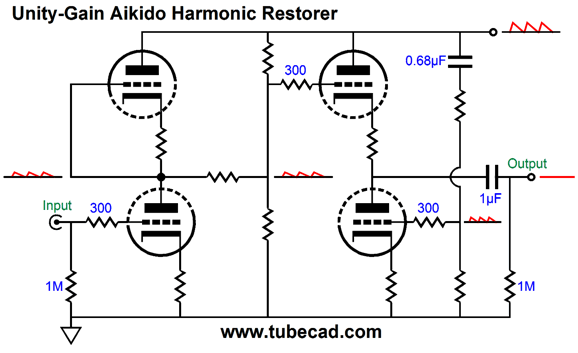
The two 3.9k resistors are effectively in parallel and they also define a 50% AC and DC voltage divider—just as the input stage's two triodes do. The result is that we can use the old Aikido formula: R2 = R1[(mu - 2) / (mu + 2)], where R1 is the top resistor and R2 is the bottom resistor below the 0.68µF capacitor.
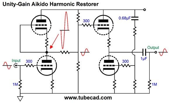
In terms of AC input signal, we see the input stage developing a high gain, which the following attenuator reduces down to unity gain.
So, are we done? We could be, but one challenge remains: not all recordings require the same amount of harmonic restoration. I own several magnifying lenses, from weak to strong. Each has its use. One size, as so often is the case, does not fit all. How do we make an adjustable amount of harmonic restoration? In other words, how do we make a variable amount of harmonic distortion? Here is one possibility.
A three-position rotary switch would allow three degrees of harmonic restoration, from mild to strong, yet each would present the same unity-gain output. The two 4.7µF capacitors ensure that the AC signal is shunted to ground, while preserving all of the DC voltage. The two capacitors are effectively in parallel, with a combined value of 9.4µF. Still, they are a pain. We could, however, replace the capacitors with resistors, as shown below.
Note how the two 3.9k resistors effectively present 1.95k of impedance to the AC signal. This resistance must be added to the attenuator's bottom resistor value. One problem is that the 3.9k resistors will get hot, plenty hot: 3.7W of heat no less. Fortunately, several companies make excellent wire-wound, high-power resistors, some of which are non-inductive designs. The two 1M resistors are there to offer protection from thumps, should the switch contacts lose contact. As I look over this circuit, I wonder how well a 6SL7 would work in the input-tube position. It would develop much higher gain and would require much larger attenuator resistor values.
Next Time
User Guides for GlassWare Software Since I am still getting e-mail asking how to buy these GlassWare software programs:
For those of you who still have old computers running Windows XP (32-bit) or any other Windows 32-bit OS, I have setup the download availability of my old old standards: Tube CAD, SE Amp CAD, and Audio Gadgets. The downloads are at the GlassWare-Yahoo store and the price is only $9.95 for each program. http://glass-ware.stores.yahoo.net/adsoffromgla.html So many have asked that I had to do it. WARNING: THESE THREE PROGRAMS WILL NOT RUN UNDER VISTA 64-Bit or WINDOWS 7 & 8 or any other 64-bit OS. One day, I do plan on remaking all of these programs into 64-bit versions, but it will be a huge ordeal, as programming requires vast chunks of noise-free time, something very rare with children running about. Ideally, I would love to come out with versions that run on iPads and Android-OS tablets.
//JRB |
Kit User Guide PDFs
And
High-quality, double-sided, extra thick, 2-oz traces, plated-through holes, dual sets of resistor pads and pads for two coupling capacitors. Stereo and mono, octal and 9-pin printed circuit boards available.
Designed by John Broskie & Made in USA Aikido PCBs for as little as $24 http://glass-ware.stores.yahoo.net/
The Tube CAD Journal's first companion program, TCJ Filter Design lets you design a filter or crossover (passive, OpAmp or tube) without having to check out thick textbooks from the library and without having to breakout the scientific calculator. This program's goal is to provide a quick and easy display not only of the frequency response, but also of the resistor and capacitor values for a passive and active filters and crossovers. TCJ Filter Design is easy to use, but not lightweight, holding over 60 different filter topologies and up to four filter alignments: While the program's main concern is active filters, solid-state and tube, it also does passive filters. In fact, it can be used to calculate passive crossovers for use with speakers by entering 8 ohms as the terminating resistance. Click on the image below to see the full screen capture.
Tube crossovers are a major part of this program; both buffered and un-buffered tube based filters along with mono-polar and bipolar power supply topologies are covered. Available on a CD-ROM and a downloadable version (4 Megabytes). |
||


| www.tubecad.com Copyright © 1999-2015 GlassWare All Rights Reserved |