| John Broskie's Guide to Tube Circuit Analysis & Design |
17 July 2016
I'm Back "Electronic circuits," was my answer. "But you were drawing those last time—and all the previous times." "Yes, that's true. I will probably be drawing them on my deathbed." "Isn't too distracting here?" "Yes and no. Actually, this is probably ideal, as I can devote only about 50% of my attention to the circuits, which allows the artistic, whimsical part of my brain to run free, resulting much greater creativity." "Creativity! What does creativity have to do with circuits?" "It's the only way that new ones can be created." "New ones? Haven't all circuits already been invented?" "In general, yes. For example, although it is unlikely, it is certainly possible that not a single new circuit can be found in your fancy smart phone. CPUs, GPUs, touch screens, RAM, WiFi and Bluetooth transceivers, digital cameras, microphones, rounded corners—all existed prior to the smart phone, which is only a novel rearrangement of existing circuits. So, new circuits are rare, but if you had asked an astronomer or biologist or cosmologist or physicist in 1890 how much remained to be discovered, I am sure that each would have said that we knew about 99% of what can be known. A thousand years from, you will get the same answer. We are always at 99%." "But circuits aren't science." "No, but they run on, or in accord, with science. They are a form of applied science, while the best are mixture of science and art, much like architecture. so while I grant that a truly new circuits are fairly rare, they certainly are possible. Ideally, a new circuit must be simple, yet novel—and most importantly, actually useful." "Simple?" "New and complicated is easy; new and simple, almost impossible." "Seriously?" "Yes, seriously. Try to invent a new simple geometric shape or a new poetic meter or a new literary genre. Hell, just try to come up with short declarative sentence that has never been uttered before."
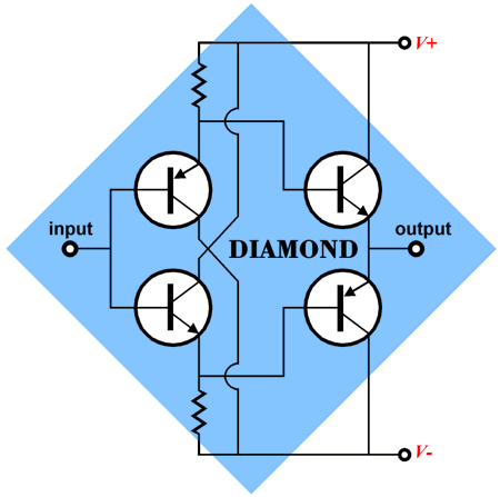
The diamond circuit is a simple buffer design whose four transistors look as if they create a diamond shape in the schematic.
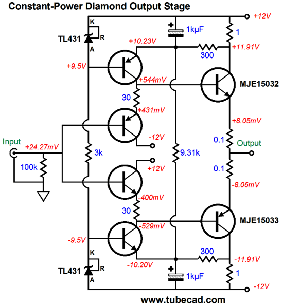
Converting this topology to constant-power requires adding more, more transistors, resistors, capacitors, and two voltage references. In addition, the output transistors must be run in class-A, i.e. the idle current must at least equal half of the expected peak output. (My original design goal here was the ability to cleanly drive 50-ohm headphones to 8Vpk in pure push-pull class-A, which implies 160mA of peak current flow.)
The TL431 ICs are configured as 2.5V shunt references, which feed the top and bottom transistors in the input stage with fixed base voltages. The two 1-ohm collector resistors monitor the current flow through the output stage. The single 9.31k resistor senses changes in the power-supply rail voltages. If the rail voltages climb, the resistor will experience greater current flow, which must be met with an equal increase in current flow through the two 100-ohm resistors, which is only possible when less current flows through the output stage. Still don't get it? The transistors hold a fixed base-to-emitter voltage, so the top transistor must see +10.23Vdc, while the bottom transistor must see -10.2V. If the wrong voltages appear at the emitters, the transistors will work to bring the voltages back in line by varying their current conduction. If the wall voltage decreases, causing the power-supply rail voltages to drop, the 9.31k resistor will see less current flow, which the 300-ohm resistors must match, so the current flow through the output stage increases. The result, in both cases, is that the output devices maintain fairly constant heat dissipation at idle. The key point here is that top and bottom transistors function in the common-emitter configuration. If the feedback mechanism eludes you, remember that using a transistor’s emitter as the input results in no phase inversion at its collector. In other words, we benefit from a smart type of auto-bias that compensates for variations in the wall voltage. How well does this constant-power feature of this diamond buffer work? The following SPICE generated graph shows how well it maintains a constant-power despite +/- 10V variation in the differential power-supply rail voltage.
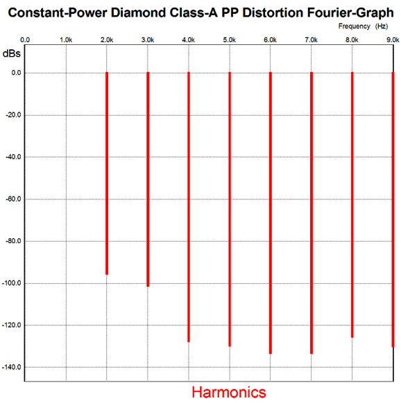
The next SPICE generated graph shows the harmonic structure of a 1kHz sinewave into a 50-ohm load at 1Vpk.
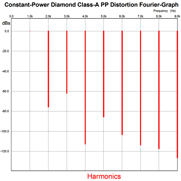
Nice, real nice. Here is what we get at full output, 8Vpk at 1kHz into 50-ohm load.
Not as sweet, but still quite fine, particularly when we take in account that no global negative feedback was employed. Okay, let’s now move on to something altogether different: a Triadtron 300B output stage.
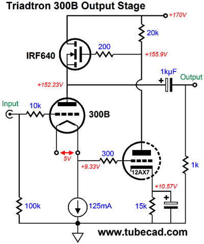
Triadtron 300B Constant-Power Output Stage
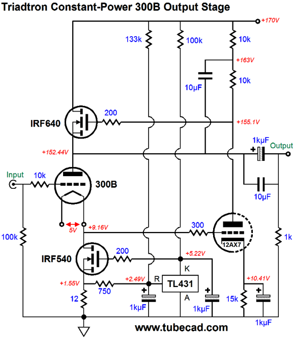
The above circuit is a hybrid power amplifier whose gain equals the triode’s amplification factor (mu). Both the distortion and output impedance are very low. The amplifier runs in single-ended, class-A mode. The 300B draws a constant current amount at all times. Yes, not just at idle, but also during music playback. How is that possible? Well, to start with, the 300B’s cathode is loaded by a constant-current source, so by extension, the 300B becomes an expensive constant-current source or sorts. The 12AX7 triode’s grid monitors the 300B’s cathode. If the cathode rises, the 12AX7’s plate falls in voltage, as the 12AX7 increases its current conduction. The N-channel MOSFET, the IRF640, sees the declining gate voltage and its source follows, while the MOSFET’s current decreases. The delta (the difference) between the 300B’s fixed current flow and the MOSFET’s is what is delivered to the external load impedance. If the 300B’s cathode voltage falls, the 12AX7’s plate climbs in voltage, as the 12AX7 decreases its current conduction. Then the MOSFET’s current increases, as its source pulls upwards. In other words, the MOSFET undergoes large current swings, while the output triode maintains a fixed current conduction. Admittedly, this is a difficult to circuit to wrap one mind around, which explains why of all my new designs this topology generates the least interest from readers. (Both a curse and a blessing.) The secret to this circuit’s operation is that the only way a triode can maintain a constant-current flow in the presence of a change in grid voltage is for its plate to change by –mu amount. For example, if +1V is presented to the grid, the plate must fall by mu times the 1V, which with a 300B output tube means by -4V. A triode's mu is a measure of its grid's effectiveness in controlling current flow through the triode relative to its plate. So, a mu of 4 means that a -1V decrease in grid voltage can be countered by a +4V increase in plate voltage. We move on to much harder stuff. Adding a constant-power function requires the usual array of essential items: a means by which we can measure the wall voltage indirectly by monitoring the change in a rectified DC voltage, say the B+ voltage; a means by which we measure the current flow through the output tube, which can be easily done by measuring the DC voltage drop across a small-valued resistor in series with the triode’s cathode; finally, we compare these two measurements to a fixed reference voltage and allow a negative feedback mechanism to make suitable adjustments to the cathode voltage.
The TL431 holds an internal voltage reference whose voltage is compared to the voltage at its reference pin. It then adjusts its current conduction as it strives to make the two voltages match each other. The 130k resistor connects to the 170V B+ voltage and the TL431’s reference pin, allowing it to monitor the B+ voltage. The 750-ohm resistor bridges the TL431’s reference pin to the top of the 12-ohm cathode resistor. The current flowing through both the 130k and 750-ohm resistors must match. The less current flowing through the 300B, the larger the voltage drop across the 750-ohm resistor. Thus, if the B+ rises, the increase current flow through must be matched by an increased flow through the 750-ohm resistor, which can only happen if the 300B cuts back on its idle current. How well does this constant-power Triadtron amplifier work? The following SPICE generated graph shows how well it maintains a constant-power despite +/- 50V variation in the B+ voltage.
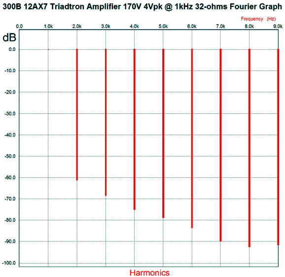
The next SPICE generated graph shows the harmonic structure of a 1kHz sinewave into a 32-ohm load at 4Vpk.
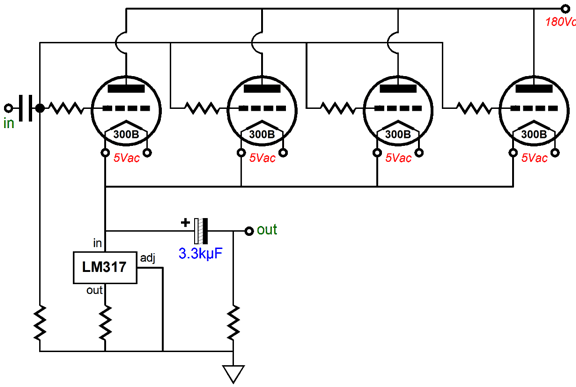
Why a 32-ohm load? Mostly, because I am making something of a joke here. I still get gobs of e-mail concerning Bruce Rozenbelt’s 1W four-300B OTL amplifier:
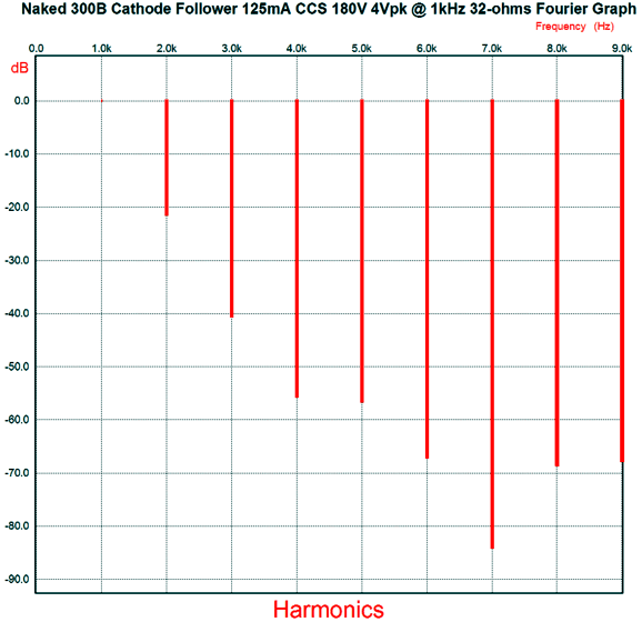
So, my thought was that it would be interesting to see how well the Triadtron would perform with four 300B tubes and an 8-ohm load. Rather than actually use four 300Bs in SPICE simulations, I used one with a load impedance four times greater. Dang fine, any way you slice it. Here is what a single 300B with constant-current-source loading working into a 32-ohm (with 180V of B+ voltage, not the Triadtron's 170Vdc) looks like for comparison.
Grim, isn't it. The only way this can be cleaned up is either to use a much higher load impedance or to apply bunches of front-end signal gain and gobs of global negative feedback around the entire amplifier. Couldn't the same amount of extra gain and negative feedback be applied to the Triadtron as well? Indeed, it could, which would lower its distortion even further. But, why bother? The Triadtron's performance is already excellent. Worse, the 300B-based cathode follower working into a 32-ohm load required 24V of peak input signal swing to deliver 4Vpk into the load, whereas the 300B-based Triadtron only required 1.06Vpk to yield the output swing. Yes, the Triadtron version realizes signal gain, not loss. Okay, I better stop here, as I could on much longer and never post.
Next Time
User Guides for GlassWare Software
For those of you who still have old computers running Windows XP (32-bit) or any other Windows 32-bit OS, I have setup the download availability of my old old standards: Tube CAD, SE Amp CAD, and Audio Gadgets. The downloads are at the GlassWare-Yahoo store and the price is only $9.95 for each program. http://glass-ware.stores.yahoo.net/adsoffromgla.html So many have asked that I had to do it. WARNING: THESE THREE PROGRAMS WILL NOT RUN UNDER VISTA 64-Bit or WINDOWS 7 & 8 or any other 64-bit OS. I do plan on remaking all of these programs into 64-bit versions, but it will be a huge ordeal, as programming requires vast chunks of noise-free time, something very rare with children running about. Ideally, I would love to come out with versions that run on iPads and Android-OS tablets. //JRB |
Kit User Guide PDFs
E-mail from GlassWare Customers
High-quality, double-sided, extra thick, 2-oz traces, plated-through holes, dual sets of resistor pads and pads for two coupling capacitors. Stereo and mono, octal and 9-pin printed circuit boards available.  Aikido PCBs for as little as $24 http://glass-ware.stores.yahoo.net/ Support the Tube CAD Journal & get an extremely powerful push-pull tube-amplifier simulator for TCJ Push-Pull Calculator
TCJ PPC Version 2 Improvements Rebuilt simulation engine *User definable
Download or CD ROM For more information, please visit our Web site : To purchase, please visit our Yahoo Store: |
|||


| www.tubecad.com Copyright © 1999-2016 GlassWare All Rights Reserved |