| John Broskie's Guide to Tube Circuit Analysis & Design |
13 August 2016
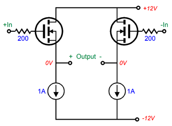
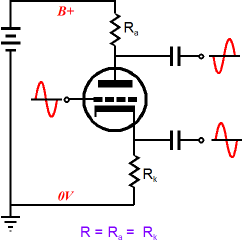
Circlotron—Once Again The great advantage of the Circlotron topology, whether it is tube-based of silicon-filled, is that the same two output devices are used and used under the same conditions. Solid-state amplifiers that hold dissimilar devices, say NPN & PNP bipolar transistors or N- and P- channel MOSFETs, are at a great disadvantage, as the two types never exactly match. Half a century ago, tube-loving folk longed for a P-version of the triode and pentode. Perhaps they were lucky not to have their wish fulfilled. Here is a balanced, 4W power buffer.
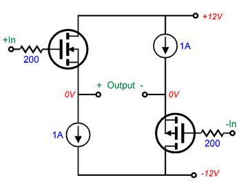
And here is another 4W power buffer.
Which would you expect to perform better? Both put out the same wattage and bandwidth and output impedance, but not distortion. Guess which offers less distortion. Now, why should being little understood make a topology popular? Let's expand that question to "Why should being little understood make anything popular?" Now that is an interesting question. Undeniably, some things are intrinsically difficult to understand, such as poorly translated instruction manuals, loony French postmodern philosophers, the concept of how a Trinity fits into monotheism, modern social sciences, and if you are a man, women; if you are a woman, men. When I was a college student, a staggeringly long time ago, I marveled at how many teachers were so infatuated with readings that eluded easy understanding— needlessly. Well, my student's guess was that much of what we were given to read was difficult to understand not because it was deep or marked by exceptional agility of intellect, but because it was defective, flawed, imperfect, and often self-contradictory. Almost the whole of sociology, psychology, and political studies fell into this category. Even English classes offered their fair share of the needlessly difficult to understand. For example, "My Kinsman, Major Molineux," a short story by Nathaniel Hawthorne, was not a work that Hawthorne was particularly proud of and he fought against its inclusion in the collection of his stories. Yet, this story was a favorite of English teachers. Another example might be James Joyce's short story, "An Encounter," which appeared in his collection of stories, The Dubliners, which was my least favorite story of the collection. I thought that this story might have become difficult to understand due to Joyce having to sidestep the censors. And these two stories were part of the good stuff; the rest were modern works. Because these needlessly difficult to understand works were flawed in some structural or technical or intellectual way, making them unnecessarily difficult to understand, my teachers, and other professional explicators, were free to impose their views and prejudices upon the works, something that the better written fiction precluded. Craziness, like water, flows into the cracks. In a similar way, the difficult to understand aspects of the Circlotron allows many audiophiles to project fanciful notions on the topology; for example, I have been told repeatedly that the Circlotron is intrinsically a class-A amplifier, no matter how little idle current flows through it, and I have been told this by not just those who make and sell Circlotron amplifiers; and that the Circlotron is actually two single-ended amplifiers. This last fancy caught me off guard, as its push-pull nature was seemingly betrayed by its accepting a balanced pair of input signals and putting out a balanced output. Nonetheless, an eager reader explained to me how the two single-ended amplifiers were tied together and how each ran as a class-A amplifier. My response: "of course you are right; the Circlotron is two SE amplifiers, just as a car is actually two motorcycles that have been tied together, but which the dull-witted fail to realize."
The Circlotron topology, which is actually an insanely simple topology, is difficult to understand due to two reasons. The first is that it holds two floating power supplies. Most power supplies do not float, being tied down tight by being grounded at one end. Floating power supplies, in contrast, float, i.e. they are not directly attached to the signal ground.
The second reason is that the signal ground attaches mid load, not at either end.
A loudspeaker is an intrinsically floating electrical device, much like a light bulb or an electric motor, as it requires no connection to "ground" to work. That most amplifiers offer a ground connection to the speaker is merely a convention, not a necessity. Bridge amplifiers do not present any grounded outputs, as neither of its outputs are grounded.
The split-load phase splitter also places the signal ground mid load, as the plate and cathode resistors share the same value. (A power supply ideally offers zero impedance to AC signals, so it constitutes an AC dead short. Therefore, imagine it absent form the following schematic and you will see how the ground falls mid load.)
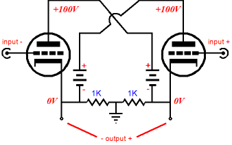
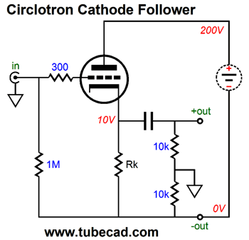
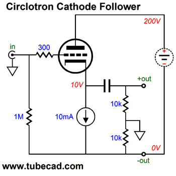
In fact, if you squint your eyes a bit, you will see that a split-load phase splitter is actually half a Circlotron circuit. Having the floating power supplies and having the input signal's ground fall mid load are truly the defining attributes of the Circlotron. So, if we drop the capital "C" and use "circlotron" to refer to an audio circuit that uses a floating power supply and that has its input signal's ground fall mid load, we can now envision a big group of circlotron circuits. Here is an example, the cathode follower turned into a circlotron cathode follower.
Moving the ground to between the two 10k resistors results in an amazing transformation, as the circuit now puts out a balanced pair of output signals and it offers differential signal gain, approaching 2 or +6dB, which is not a lot, but certainly more than the cathode follower's less than unity gain. Amazing, no? The price we pay is a slightly higher output impedance and the need for one floating power supply per channel. With a textbook cathode follower, the output impedance is roughly equal to rp/(mu + 1); with the circlotron cathode follower, 2rp/(mu +2). Ground is found in the nexus of the two 10k resistors and bottom of the floating power supply bounces up and down along with the output signal. Thus, two channels cannot share the floating power supply. What happens if they do? Not good. The two channel's signals will bleed together in a sonic mess. Speaking of floating power supplies, my using a new symbol for a floating power supply was the result of a recommendation by Jeremy Epstein.
I used to use the battery symbol, which confused many, as they thought at a battery, which is a floating power supply, was actually needed; it isn't; it is sufficient, but not necessary. This symbol is less likely to do so, as it looks similar to some SPICE voltage-source symbols. It reminds me of the symbol I created for the compliant current source.
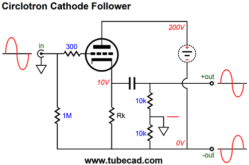
Returning to lowercase circlotron circuits, we can replace the cathode resistor with a constant-current source, which would greatly improve the performance.
Think of this circuit as an unbalanced-to-balanced converter circuit, i.e. a variation on the split-load phase splitter.
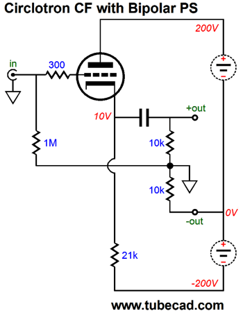
Each output is slightly lower in amplitude relative to the input signal. Add the two outputs together differentially and the sum is almost twice as large as the input signal. Once again, note that each channel must get its own floating power supply. Also note that we could use a floating bipolar power supply.
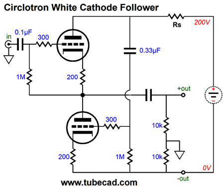
What's missing is the signature TCJ protection diode between the inverting output and the cathode. What! Are you crazy John!? The inverting output will swing to negative 200V if the tube is cold or missing from its socket. Actually, it won't, as it will remain at 0Vdc. The 21k cathode resistor will get warm, much as it does during normal operation, but since the power supply floats, the two outputs remain at 0Vdc. Let's move on to a more complex circuit, the White cathode follower ala circlotron.
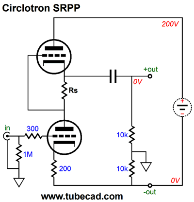
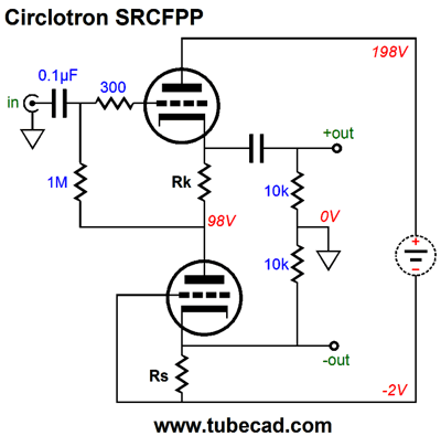
The White cathode follower belongs to a club with three members: the White cathode follower, the SRPP, and the SRCFPP. All three are push-pull circuits that create a needed anti-phase signal by including a current-sense resistor. In the White cathode follower, this resistor appears at the top; in the SRPP, in the middle; and in the SRCFPP, at the bottom. The White cathode follower and the SRCFPP are push-pull buffers that offer a gain slightly less than unity. The darling of the solder-slinging community, the SRPP, offers signal gain. All three circuits are absolutely load dependent, as the load impedance dictates the value of the current-sense resistor. If you drive a different load impedance, then you need a different current-sense resistor value.
It may look different, but it uses the same formula for selecting the current-sense resistor: Rs = (rp + 2Rload)/mu.
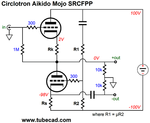
The SRCFPP is the hardest to understand, but it works in the same fashion as the other two current-sense-resistor-based push-pull circuits. The big difference is that the bottom triode's grid doesn't receive the anti-phase drive signal, its cathode does, making the bottom triode function as a grounded-grid amplifier. The top triode functions as a cathode follower. As a positive input voltage is encountered, the top triode's cathode pulls up, increasing the current flow through the external load, which must also flow through the Rs resistor at the bottom, which increases the bottom triode's cathode voltage, which serves to decrease this triode's current conduction. When the top triode's cathode decreases its current flow, the bottom triode sees a lower cathode voltage, so its conduction increases and the increased current flows in the opposite direction through the load and the coupling capacitor and the bottom triode. In a nutshell, push-pull operation. The above circuit works well in SPICE simulations with a 6DJ8 tube model and Rk & Rs resistor values equal to 115 ohms and the external load impedance set to 300 ohms. The PSRR was a respectable -28dB. Of course, I could not resist applying some Aikido mojo, with the following as a result, which exhibited a PSRR figure closer to -60dB in simulations.
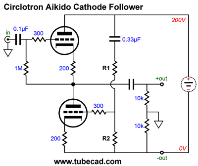
Moving on to other buffer circuits, my own Aikido cathode follower transforms into the following circlotron version.
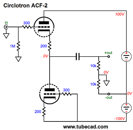
Unlike the White cathode follower and the SRCFPP, the Aikido cathode follower is a purely single-ended affair, where no push-pulling obtains. By the way, the ACF-2 can be turned circlotron with a floating bipolar power supply.
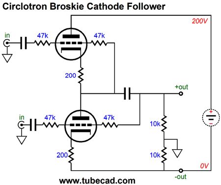
Why use a coupling capacitor if both side of the capacitor see 0Vdc? They do in SPICE simulations, as SPICE 200-ohm resistors are matched to 0.000000000001%, just as the triodes are. Reality differs. In reality, we can expect some DC offset on the left side of the coupling capacitor. Of course, if the balanced amplifier being driven presents coupling capacitors at its input, we could probably get away with losing the circlotron ACF-2's coupling capacitor. The normal Broskie cathode follower accepts a balanced input signal and delivers a low-output impedance unbalanced output signal. The circlotron version is balanced in and balanced out. Why bother, if the input signal is already balanced? The answer is a low output impedance and a high common-mode rejection ratio (CMRR).
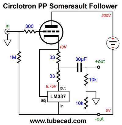
Unlike the White cathode follower and the SRCFPP, the Broskie cathode follower is not load dependant. Like these two buffers, it is a class-A push-pull buffer. In fact, because it does not need to create its own anti-phase signal, as it already sees a pair of balanced input signals, it puts out a cleaner output signal. I remember receiving an e-mail almost two decades ago from a European reader who told me that the BCF was great at driving his 300-ohm headphones. I didn't think it possible, so I replaced the existing 0.68 µF coupling capacitors in my BCF with two 47µF capacitors and hooked up my own Sennheiser 300-ohm headphones. Mercy. He was right. The following circuit should have appeared earlier, but I feared that the solid-state device, the LM337, would scare away too many readers. The somersault circuit is truly amazing. The LM337 acts as both an auto-bias circuit and as an active push-pull complement, creating a class-A push-pull buffer.
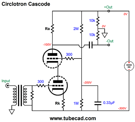
Not only buffers can receive the circlotron treatment, as we can apply it to a high-gain circuit, such as the cascode.
Since you have read my recent post on the cascode, you know that the cascode offers wide high-frequency bandwidth and high gain, but dismal PSRR. Not so with the circlotron version, as the PSRR is exemplary, while still retaining the cascodes other desirable attributes. The downside is that we must use an input transformer. (Actually, a good signal transformer can prove a godsend, albeit an expensive one.) Conclusion, the circlotron transform requires a floating power supply and placing the input signal's ground mid load.
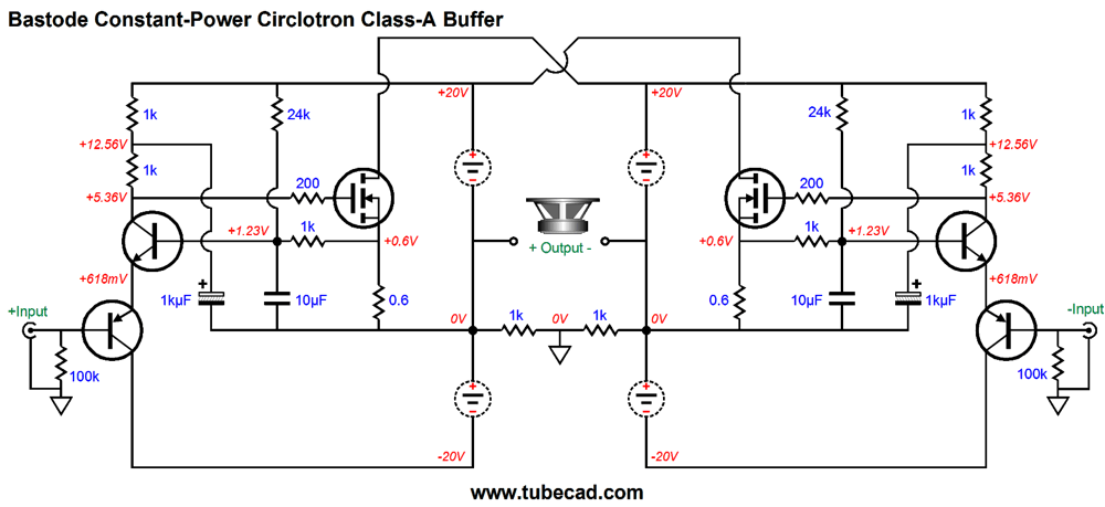
Constant-power Circlotron But John tube Circlotron power amplifiers run super hot. Indeed they do. But heater-generated heat does not count. A 6AS7 triode draws 2.5A of heater current. Ultimately, this is a liability, not an asset. The 6AS7 triodes (there are two per glass envelope, just like a 6SN7) bears a 13W plate dissipation limit and a 200mA cathode current limit. Thus, if eight 6AS7 tubes were used, a total of sixteen triodes, in a Circlotron output stage, each with a 100V cathode-to-plate voltage and each running a high 100mA idle current would create 160W of plate dissipation at idle, each triode experiencing 10W of dissipation. The eight heaters would generate 126W of heat dissipation. Okay, surely such a beast would produce gobs of class-A watts, right? Wrong. A tad over 10W is the class-A window of operation into an 8-ohm load. Of course, this Circlotron could deliver many more class-AB watts, say about 50W more. The punch-line here is that constant-power operation does not apply to class-AB output stages, only class-A ones. The Circlotron, filled with vacuum tubes, cannot belong to the class-A club, advertising copy to the contrary, without using dozens and dozens of output tubes under a high idle current. In contrast, solid-state and hybrid Circlotrons can be run in strict class-A mode and these Circlotrons can be made to operate in constant-power mode. The following MOSFET-based Circlotron operate in constant-power mode.
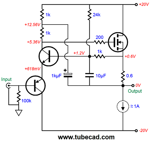
The bastode driver stage strives to keep the output inline with the input signal. It also works to auto-bias the power MOSFETs. To better see how this works, let's examine just half of the Circlotron circuit, which we reconfigure as a simple single-end power buffer.
The compliant constant-current source adjusts to whatever idle current the MOSFET falls into. The bastode's NPN transistor's base sits at 1.2Vdc. This voltage is the sum of the two transistor emitter-to-base voltage drops and it functions as a free voltage reference. If the wall voltage climbs, then the 20V power-supply rail voltages will also climb in voltage, which will prompt an increase in current flow through the 24k resistor, which must be matched by an equal increase in current flow through the 1k resistor, which is only possible if the resistor sees a bigger voltage drop, which is only possible if the voltage drop across the 0.6-ohm source decreases, which implies that the idle current through the MOSFET has dropped. If the wall voltage falls, then the idle current goes up. We can add more MOSFETs to the output stage, of course.
Four MOSFETs, each running under a 500mA idle current allows 16W of pure class-A power to be delivered into an 8-ohm load. This might not sound like much power, but I bet it plays louder than you might expect. Getting more watts requires higher floating power-supply voltages and many more MOSFETs and a much bigger heatsink. The following table lists the required peak current and voltage swings to deliver the stated watts into an 8-ohm load.
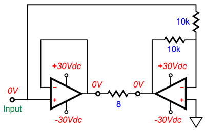
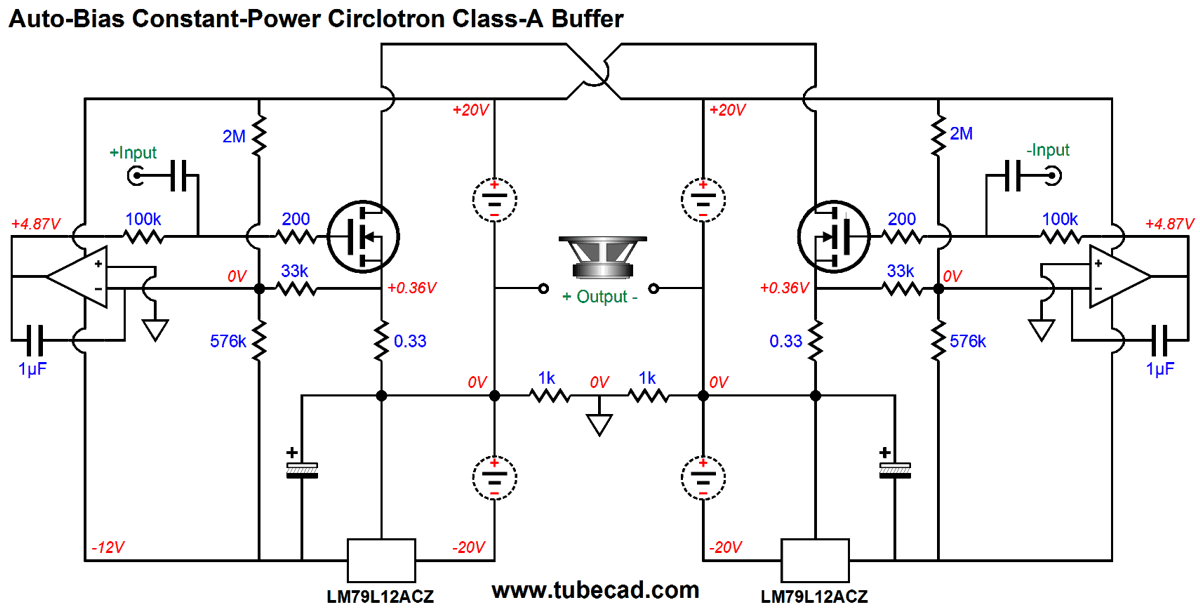
If you desire 64W of pure class-A power, then the Circlotron must idle at 2A (each bank) and the floating power-supply voltage should be close to 40Vdc, which implies 160W of heat at idle. If we adopt my own maximum heatsink temperature of 60C, then we must subtract from 60C the ambient temperature, say 25C, getting 35C, which we then divide by 160W to find the maximum maximum heatsink thermal resistance, which would in this example be 0.21875C/W. This is a huge heatsink. So much so, in fact, that a forced-air heatsink setup might be preferred. This is why 100W class-A amplifiers are not common. Remember that the theoretical maximum efficiency for a push-pull class-A amplifier is 50%. Note that this example dissipated 160W and deliver only 64W, an efficiency of only 40%. This is reality. Hard, hot reality. Had we used tubes instead of MOSFETs, the efficiency would likely be less than 10%, not including the heat lost to heating the heater elements and power supply losses. In other words, if you desire a 100W class-A, tube-based Circlotron amplifier, then you would have to make arrangements with your power company to supply you listening room with its own dedicated feed and 30A fuse box. Assuming the same 40% efficiency of the 16W MOSFET-based class-A Circlotron output stage, 100W of output watts would result in 250W of heat at idle per channel. I used run a three-way tri-ammped system that used three 20W solid-state amplifier of my own design. So, did it play as loud as a 60W amplifier would. No. My system could not deliver 60W of organ music floor shaking. It did, however, sound much more powerful than 60W with other music, sounding closer to 200W. How was that possible. Our ears evaluate loudness based on actual sound pressure and on distortion. Thus, we plug our ears when a fool walks by blaring his blaster radio; yet, the SPL is actually modest, but the THD is horrendous. Well, my tri-ampped system seldom, if ever, clipped the tweeter amplifiers. The ear can instantly hear high-frequency clipping, but not low frequency clipping. My amplifiers each held a clip indicator LED, which would glow orange when approaching clipping and red when clipping. The woofer amps flickered red all the time; the midrange amplifier, seldom; and the tweeter amplifier, almost never. See Bi-Ampping Psycho-Acoustics. An added benefit to tri-ampping was that the midrange and tweeter didn't need a power-wasting two-resistor attenuator, as I set the volume before the amplifiers, not after. Most woofers are much less efficient than midranges and tweeters. Moreover, passive crossover elements are both big and expensive—and clunky. You might be running $22,000 speaker cables, but the passive crossover holds hundreds of feet of 18G magnet wire in its inductors, which also reduce woofer efficiency due their DCR. Passive crossovers are a pain. In short, building three 16W class-A Circlotrons would undoubtedly out perform one 48W class-A Circlotron. Mind you, you might get the best sonic bang for buck by using a 100W, class-AB Circlotron for the woofer; a 16W, class-A Circlotron for the midrange; and a 4W, class-A Circlotron for the tweeter. That's great John, but where are the tubes? Ah, the tubes. I would build a balanced-output, tube-based line stage amplifier that could swing 16V peak. Then I might build the following design that only uses the OpAmps for setting the constant-power auto-bias.
The LM79L12ACZ is a $0.70 TO-92 fixed -12V voltage regulator. The OpAmps only monitor the rail voltage and the idle current, resulting in a constant-power operation, but they do not control the MOSFET's AC workings. The only negative feedback results from the MOSFETs' own degenerative feedback due to their being used as source followers. How well does it all work?
Not bad. The THD was close to 0.01% in SPICE simulations at 16W output into 8-ohm load at 1kHz. The bastode driver stage offers even lower distortion, as it enjoys more negative feedback.
Next Time
//JRB
User Guides for GlassWare Software
For those of you who still have old computers running Windows XP (32-bit) or any other Windows 32-bit OS, I have setup the download availability of my old old standards: Tube CAD, SE Amp CAD, and Audio Gadgets. The downloads are at the GlassWare-Yahoo store and the price is only $9.95 for each program. http://glass-ware.stores.yahoo.net/adsoffromgla.html So many have asked that I had to do it. WARNING: THESE THREE PROGRAMS WILL NOT RUN UNDER VISTA 64-Bit or WINDOWS 7 & 8 or any other 64-bit OS. I do plan on remaking all of these programs into 64-bit versions, but it will be a huge ordeal, as programming requires vast chunks of noise-free time, something very rare with children running about. Ideally, I would love to come out with versions that run on iPads and Android-OS tablets. //JRB |
Kit User Guide PDFs
E-mail from GlassWare Customers
High-quality, double-sided, extra thick, 2-oz traces, plated-through holes, dual sets of resistor pads and pads for two coupling capacitors. Stereo and mono, octal and 9-pin printed circuit boards available.  Aikido PCBs for as little as $24 http://glass-ware.stores.yahoo.net/ Support the Tube CAD Journal & get an extremely powerful push-pull tube-amplifier simulator for TCJ Push-Pull Calculator
TCJ PPC Version 2 Improvements Rebuilt simulation engine *User definable
Download or CD ROM For more information, please visit our Web site : To purchase, please visit our Yahoo Store: |
|||||||||||||||||||||||||||||||||||||||||||||||||||||||||


.png)


| www.tubecad.com Copyright © 1999-2016 GlassWare All Rights Reserved |