| John Broskie's Guide to Tube Circuit Analysis & Design |
03 September 2016 Strengthening the Tube CAD Journal
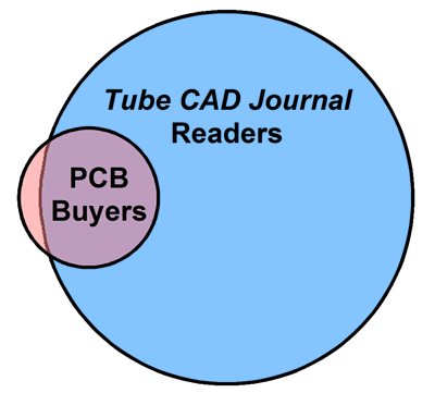
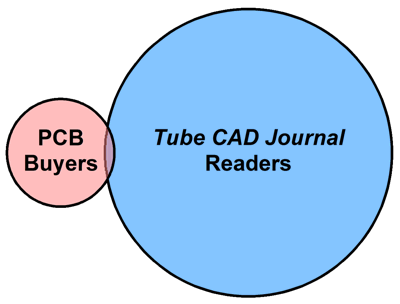
Makes sense, doesn't it? I thought only those who read the Tube CAD Journal would want to buy PCBs. But the reality is much closer to this diagram:
Most of those who buy the PCBs used Google to find them. Many do not even read English. One clue that I ignored for the longest time was that I kept getting e-mails from PCB purchasers who asked if the board could be used in a particular way. What struck me odd about the question was that I had spent half of my last post on just how this could be done. Had he not read the post? No, he hadn't. My efforts also differ from most other web realities, as most websites begrudgingly post content to promote sales of stuff; I begrudgingly sell stuff so that I can lovingly produce and post content. Over the years, I have received generous requests asking how the devoted reader could monetarily contribute to my postings. My usual answer has been to ask the reader to buy either a software download or a PCB. But not everyone needs these items or can use them. (One reader, however, has repeatedly bought the same software download each year. I wrote to him and he explained that this was his way of contributing to the Tube CAD Journal.) Some readers have just—unasked—sent in checks, one of which was for an embarrassingly large amount. Embarrassing for me, as I wish I could afford to make a similar contribution to my favorite websites; I do contribute to at least three websites, but nothing so generous. "Most websites begrudgingly post content to promote sales of stuff; I begrudgingly sell stuff so that I can lovingly produce and post content." Well, I have decided to listen to my ardent readers and friends and set up a Patreon account. If you wish to assist, bolster, and strengthen my efforts here and you are so inclined, please do check out my Patreon link. Thanks.
Unbalancing the Differential Amplifier
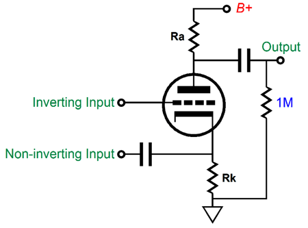
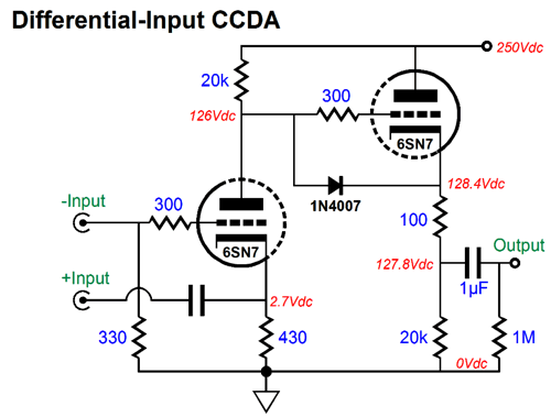
The key feature to a balanced system is that the signal source presents the same impedance on both of its two wires and that the receiving circuit presents equal impedances on both of its inputs. This is not possible with the usual grounded-cathode or grounded-grid amplifiers, as the cathode (and cathode resistor) presents a vastly lower impedance than the grid. One workaround is to load down the grid; for example, here is balanced-input CCDA.
Both inputs present the same low input impedance, which would be suitable for transformer loading. If we replace the 430-ohm cathode resistor with a constant-current source, we could replace the 330-ohm input resistor with a 1.2k resistor. The reason we care about differential amplifiers is that they amplify only differences and ignore what is common, shared, equal between the two signal wires. What follows employs the old Unbalancer and the new Unbalancer Two as examples, but is in no way limited to these two circuits. The novel approach is universal, but the examples are particular.
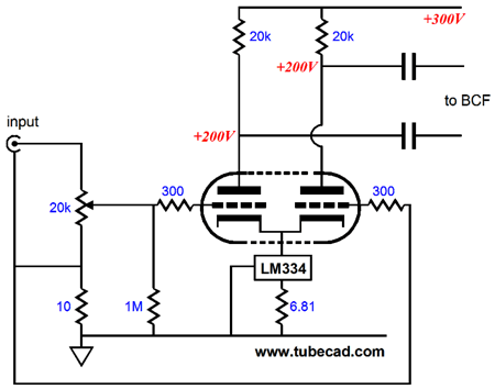
Unbalancing the Unbalancer Two Since I am adverse to repeating myself too much, some is okay, but not too much (I would make a poor columnist or politician), please read or reread post number 241 and post number 270 for more details. Here is the setup that I had tried before.
The Unbalancer holds a differential input stage, and I connected the non-inverting input to the RCA jack hot pin, while I connected inverting input connected to the RCA jack ground lug, but not to the Unbalancer's ground, as the ground lug found its path to the Unbalancer's ground through a 10-ohm resistor. In other words, I floated (or lifted) the RCA jack grounds.
Normally, with an unbalanced setup this is a bad idea, as it usually results in a buzzing hum. Turning up the volume makes the resulting hum unbearable. Not with the Unbalancer, as the differential input stage's high common-mode rejection (CMRR) rejected the hum, resulting in a hum-free output.
I held high expectations that the configuration would work again with the Unbalancer Two, as I had also wired up the topology long. long ago in a solid-state power amplifier that I had modified. Still, I was a bit apprehensive, as I feared the wild squeal that an amplifier blares when it loses its connection to the signal source's ground. No squeal... With the old Unbalancer—even before the first notes of music sounded—I could hear the difference, as subtle sonic clues as to the recording room's dimensions and the placement of the ready musicians, the horn player inhaling, the bass player leaning forward—all were disclosed by the seeming silence. Thus, I was eager to hear repeat performance by the new Unbalancer Two. At the same time I know that no one is as easy to fool as myself. As the wonderful and wise Richard Feynman put it:
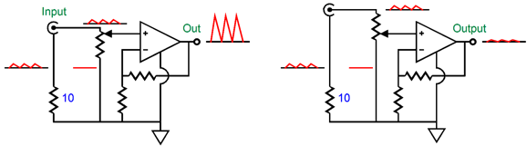
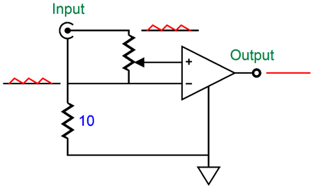
Heeding Mr. Feynman's counsel, I wired up a rotary switch so that I could switch between fancy and ordinary, ordinary being where the inverting input is grounded. I set the switch to fancy, queued up the play-list, sat down, cleared my mind, and pressed the play button. Disappointment reigned. The silence remained silent, revealing no subtle sonic clues, failing to recapture the original Unbalancer's performance in the same application years ago. I felt like the disillusioned woman who discovers that her blind-date is the not the Brad-Pit-grade Adonis whom she had been promised, but finds that her date reminds her more of a young Woody Allen, but without Allen's imposing stature and manly physique. Actually, the sound was fine, but that certain something else was missing. Here is another analogy: over two decades ago, a group of my audiophile friends and I made the long trip down to see a tube-loving friend who had built a dedicated listening room onto the back of his house. We had a great time and he wished to thanks us for making the over 100-mile journey to his place by taking us out to lunch at his small town's best restaurant, which he spoke glowingly of. My taste buds were ready. We arrived at a chain restaurant like a Applebees or Chili's or Ruby Tuesday. No doubt it was his small town's best restaurant, but as we had driven from the San Francisco Bay Area, our expectations were a tad higher; being his town's best restaurant was much like being his town's tallest building. I realize that this last analogy falls short, as what I expected to hear was not the usual small incremental move up the Hi-Fi ladder in sound quality. No, what I sought was something rarer. Here is my last attempt: I used to be famous for making a fine banana bread. I once offered a slice to a friend and he politely declined, stating that he didn't like banana bread. I told him that he should try it anyway, as it was different from the others. Reluctantly, he took a bite. He exclaimed, "This is delicious; no, I mean it; I am not being polite. Why do I like your banana bread when I don't like all the others?" "I use a secret ingredient." "What is it?" "Lemon zest, lots of it." Well, my experiment lacked lemon zest. Crestfallen and abject, I sought answers. My first guess was that the original Unbalancer's much higher gain resulted in its better results, but why higher gain should make any difference made no sense to me. CMRR is CMRR, regardless the gain. Isolation transformers offer no gain, but yield superb CMRR. I wondered if I had originally grounded the old Unbalancer's chassis to the house ground, which I hadn't done this time. I concluded that this would have made things worse, not better. I then worried about the digital attenuation and its potential problems compared to the A3 stepped attenuator I had used with the original Unbalancer in this arrangement.
Digital attenuation is an interesting topic. In a nutshell, if a 16-bit DAC is fed a 16-bit signal, then attenuation by shifting the ones and zeros about might result in resolution loss, as the attenuation might move the resulting output signal below the DAC minimum output signal. In the same way, digital volume increases might run into the DAC's other hard limit, its maximum output. Lossless digital volume increases are possible, as long as the resulting shifting does not exceed the DAC maximum output. If the increase goes beyond the DAC maximum output, clipping occurs. Remember, a DAC is an integer cruncher; any number to the right of the decimal place is ignored. In other words, if applying digital attenuation results in a number smaller than 1, then that number is rounded down to zero. For example, if 15 is halved (-6dB), the DAC puts out 7, as it cannot deliver 0.5 increments or decrements. On the other hand, if a 16-bit data-stream is fed to a 24-bit DAC, then lossless digital attenuation is possible up to point. Where is that point? Since the 24-bit DAC has eight more bits to play with, we take 2 and raise it to the 8th power, which yields 256; we then take the log of 1/256 and multiply the result by 20 to get the amount of dBs possible in lossless attenuation; in other words, -48dB is the limit to lossless attenuation in this example. The same 16-bit signal fed to a 32-bit DAC should yield a limit of -96dB of lossless attenuation. As I pondered the possible answers to why the silence didn't bark, I decided to switch the arrangement to ordinary setup where the Unbalancer Two's inverting input is grounded. Bingo. Loud and obvious, the silence spoke. I had got the positions on the rotary switch wrong. Now, with the switch in the correct position, the same sonic satisfaction that the old Unbalancer had achieved resurrected itself. The alteration in sound changes neither the frequency balance nor the dynamics (nor drive, slam, pace, shimmer…). It is like moving to a finer-grain photo film or a steadier grip on the camera, as the photo's objects remain in the same proportions and colors, but differ in fine clarity. Bad recording still sound bad, but those rare fine recordings sound finer still. I loved these results, both my disappointment followed by contentment, as my initial dissatisfaction vouchsafed my later satisfaction. Mind you, the effect is subtle, but easily discerned when you hear it. Or maybe not. I know that my house wiring is off, as I measure a small AC voltage between the wall outlets ground terminals. Perhaps, with a more cleanly laid out house wiring, the results would dim to imperceptibility. But I doubt it, as I believe this arrangement overcomes a structural flaw in how all unbalanced audio gear is made.
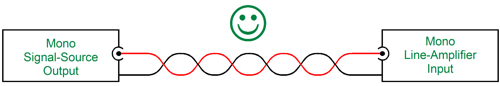
Mono, Glorious Mono
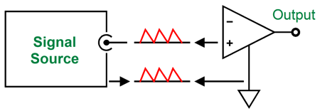
The signal source's ground becomes the line amplifier's (or power amplifier's) ground. If we leave both unconnected and attach a scope to both, we see noise existing between the two pieces of equipment.
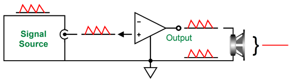
If we attach the tow units together with an interconnect, the noise still exists, say relative to the house ground, but this is not an audible problem, as the speaker is a naturally differential device, which entirely ignores common-mode noise.
With the introduction of stereo, we should have seen a concomitant introduction of a new stereo connector. We were not that lucky. It was as if the move from the monocle to glasses had been sidestepped by the introduction of two monocles rather than one frame holding two lenses. What went wrong? I cannot help but quote myself quoting someone else:
A new stereo connector would have proved expensive and not have proved backward compatible. (A backward-compatible stereo version of the RCA plug and jack could have been made, however, by notching the ground sleeve and splitting the prong in half lengthwise and separating each channel with thin plastic. A special stereo-to-mono interconnect could then have been made that would include two 10k resistors in series with the two hots, so the stereo signal source would not be harmed by the summed left and right signals.)
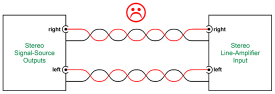
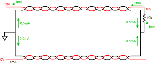
In other words, we went from one set of RCA jacks and cord to two sets. So, what was wrong with that? Stereo equipment holds two audio signals, but not two grounds, i.e. the signal reference. If strict dual-mono construction, however, had been universally followed, where dual-mono phono preamps fed dual-mono line-stage amplifiers that in turn fed dual-mono power amplifiers, then two grounds would have existed, and two RCA jacks and two RCA-terminated cords would make sense. In this actual world, the one I happened to have made my home, we got stereo phono stages and stereo line-stage amplifiers and, of course, stereo power amplifiers. Amazingly, loudspeakers managed to stay dual mono. As a result, we ended up with many duplicated ground connections. Is this a problem? Here is an example, against your spouse's wishes, you have bought a pair of $6,000 interconnects, knowing that the Hyper-Space-Time wire topology, where the signal and ground wire weave in accord with mathematically proven configuration guaranteed to ensure sonic bliss, as you know that nothing is more important than good interconnects, as they—and they alone—allow the musical genie trapped in the oil lamp to escape. The Hyper-Space-Time construction permits perfect signal flow through the interconnect, or does it? The stereo CD player (or DAC or tuner or phono stage) connects to your $10,000 stereo line-stage amplifier, presenting 10V of audio signal in only the left channel. Within the line-stage amplifier a 10k volume control interrupts the signal's flow back through the ground wire to the CD player, causing a current flow of 10/10k mA, or 1mA, which the Hyper-Space-Time wire topology perfectly balances between signal and ground wires, preventing the slightest loss in fidelity. In fact, the left channel's interconnect's ground wire only sees half the current flow as its “hot” signal wire sees. How is that possible, where did the other half of the current flow go?
It went down the 10k potentiometer to the line-stage amplifier's ground and then down the right channel interconnect's grounded wire. Didn't the current know better? Why didn't it stick to only the left side? How is the magic of Hyper-Space-Time wire topology going to obtain if the right interconnect sees left channel current flow, thereby disturbing the Hyper-Space-Time laws of physics? Current, like water, flows where it can. Both interconnects offer the same impedance back to the CD player, so the current divides equally between interconnects.
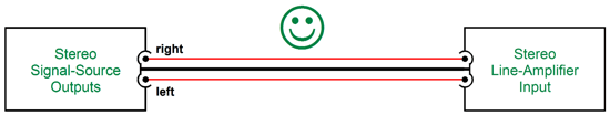
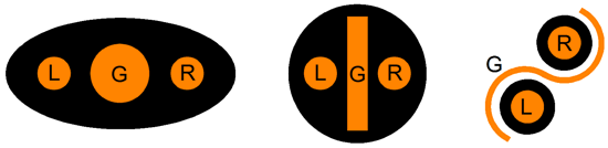
Now, if we had always used a three-wire stereo connector, we would all know that left and right signal currents always flow up and down the single ground wire, so we would never have been tempted to create Hyper-Space-Time wire topology in the first place. Instead, we would have probably made something like a stereo interconnect that held two skinny wires and one fat wire for ground. Or, perhaps, if we felt particularly snazzy, we would replace the single ground wire with a flat copper strip, which could provide better isolation between channels; or, fancier still, we could use a copper foil wrap to create a yin-yang ground shield.
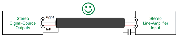
In other words, no worries, as you could still have bought a $3,000 stereo interconnect, assuming that one cord should cost half as much as two. Of course, with high-end audio, such assumptions seldom apply. The last example is only partially shielded, but what about shielding a three-wire stereo interconnect?
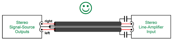
The best approach is to only ground the shield at the signal source end of the cable. At the same time, we cannot leave the other end floating in the air, as it the shield will become a radio antenna. Terminating the shield at the output end with a small-valued capacitor undoes the antenna. My own preference would be to use dual shields, one for each channel.
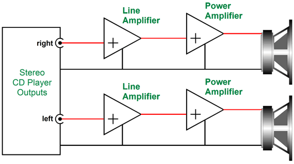
Since we are stuck with RCA plugs and jacks, how can we move forward? A differential input stage. But before going any further, I must give credit to the late David Manley of VTL, Manley Laboratories, and the ViTaL record label fame. Back in the 1980's, he was kind enough to indulge my one-hour cross-examination as we sat in the shade of a large tree, cigarette after cigarette filling his lungs. He would have made a poor magician. Unlike all the other tube gurus that I had met, he was not secretive; indeed, he couldn't stop spilling the beans. I thought he was wrong on a few small points of tube electronics, but I was smart enough to shut up. The knowledge was flowing from a higher elevation to lower one, from him to me. Nothing disturbs me more, except of course torture and decapitation and microphonic tubes, than the way many behave in the presence of the famous; asking questions that they already know the answer to or asking questions that Google would answer in 0.001 seconds or trying to show off before the eminent by asking questions that are meant to exalt the questioner; for example, "Given that the uncertainty principle, Werner Heisenberg's great but not only contribution to modern physics, actually states a fundamental property of quantum systems, and is not merely a statement about the want of observational success due to the limits of current technology, inherent as it is in the properties of all wave-like systems, do you like Italian cars?" The last thing I wanted to do was stop the flow of tube knowledge from David's expertise. Manley told me about an interesting situation: he said given a CD player and two dual mono line stage amplifiers and two dual mono power amplifiers and two speakers, wonderful stereo imaging obtained, far better than normally heard with stereo line-stages and stereo power amplifiers.
He went on to say that you need only take a long wire to bridge the two amplifier chassis to ruin this fine stereo presentation. Why this occurred, he couldn't explain. At the time, I thought his anecdote to be very odd: How could making the grounds even more secure result in worse sound? It's as if you were told that your pants are more likely to fall down if you wear both suspenders and a belt. Still, this story has haunted me since. If there's a difference, they must be a reason behind it.
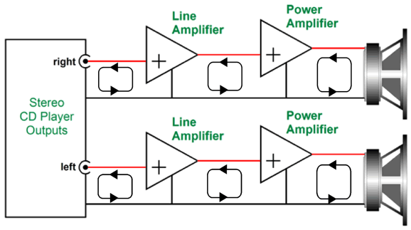
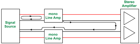
Note how all the signal current flows define small loops from one stage to the next. If the two monobloc power amplifiers are replaced by a stereo amplifier the loops bleed together. For example, imagine audio signal in only one channel. A current flow circles from signal source to the dual-mono line stage for that channel. So far, very good. But since the dual-mono line stage's ground also attaches to the stereo power amplifier, which attaches its ground to the other dual-mono line stage, which in turn attaches to the signal source ground, a second current path is available and signal current will flow through it.
Now I know audiophiles who carefully ensure that each speaker cable is within 1/10 of an inch of each other in length, as they fear time discrepancies between channels. Yes, such people exist. Note that one current path in the example above is much longer than the other. How can the Hyper-Space-Time wire topology hope to deal with this misalignment? It can't. In other words, unless you are running dual mono power amplifiers, do not bother with dual mono line stages. Returning to my experiment with floating RCA-jack grounds, adding the two 10-ohm resistors presents a relatively high resistance between left and right channel ground connections. Thus, repeating the same thought experiment, wherein 1V of signal is present in only the CD player's left channel, the left channel's signal current—after flowing through the 10k potentiometer—sees two current paths back to the CD player, with the left interconnect presenting 0.0001 ohms of resistance, while right presents 20.0001 ohms, so the signal current flows through both, but not in equal measure, as 20,000 times more current flows through the left channel's interconnect, not the usual 50% that normal setups exhibit. Now, the Hyper-Space-Time wire topology can really shine—or is it sound?
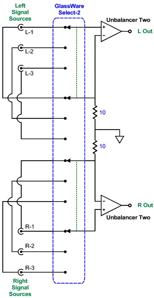
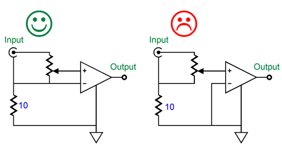
We can use the Unbalancer Two PCB's resistor's R20 to position the 10-ohm resistors, while using the DC input on the inverting input pads on the PCB. Using a GlassWare Select-2 selector switch allows us to select between three signal sources, both the hots and the grounds. By using floating RCA jack grounds and a differential line stage amplifier, if you like your interconnects, you can keep your interconnects—but this time it's true. What is important is to remember that the volume control cannot terminate into ground; instead, it must terminate into the RCA jack's ground lug. In other words, a volume potentiometer that offers only one ground connection will not work, as each channel must get its own ground connection to its own input signal RCA jack; nor can you use a long wire bus that attaches to all the RCA jack ground at once. Each input signal RCA jack must be isolated from the chassis and all the other RCA jack grounds.
Failing to set it up this way will result in hum. By the way, I decided to experiment with the 10-ohm resistor value. As you have probably surmised, I like to think to extremes. Thus, I replaced the 10-ohm resistor with a 1-meg resistor. Hum, not a ton, but a small amount of hum, which is far more than I can tolerate. I should have tried 1-ohm and 100-ohm resistors. Maybe next week.
Using a CCDA Instead
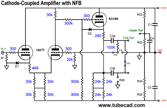
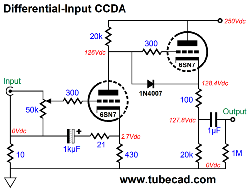
But many want something simpler and prefer to use point-to-point wiring. No problem. A simple CCDA could be used.
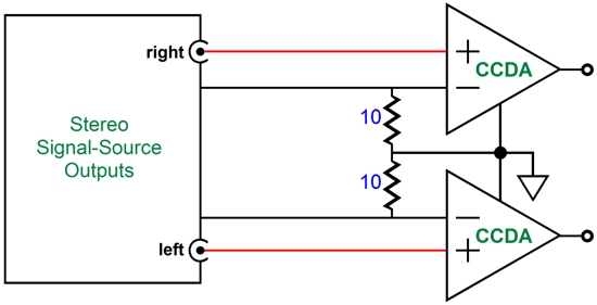
One 6SN7 (or 6CG7 or ECC99) per channel is all that is needed. The 1kµF input capacitor will offend many reader's sensibility, but in all probability their CD player or DAC already uses one as an output coupling capacitor. The horror! I would use a non-polarized electrolytic capacitor, such as the those made by Panasonic, as they sound great; and bypassing this capacitor with quality film capacitor wouldn't hurt. The 21-ohm resistor is needed to improve the input triode's CMRR. In effect, this input stage functions as both a grounded-cathode and grounded-grid amplifier; thus, we must ensure equal signal gain from both inputs, so that common-mode signal is rejected at the plate. By the way, note how the two 10-ohm resistors are actually in parallel.
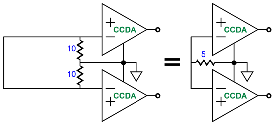
Not 20 ohms but 5 ohms separate the signal source and the CCDA ground.
Actually, it is a tad lower than 5 ohms, as the 6SN7's cathode resistor and the 21-ohm series resistors add up to 5451 ohms, which shunts each 10 -ohm resistor. Once again, what I thought would prove a short post turned into a long and elaborate explication. And another once again, if so inclined, please do check out my Patreon link. (I would really love to make it to post 1,000, being already more than a third of the way there.) Thanks.
//JRB
User Guides for GlassWare Software Since I am still getting e-mail asking how to buy these GlassWare software programs:
For those of you who still have old computers running Windows XP (32-bit) or any other Windows 32-bit OS, I have setup the download availability of my old old standards: Tube CAD, SE Amp CAD, and Audio Gadgets. The downloads are at the GlassWare-Yahoo store and the price is only $9.95 for each program. http://glass-ware.stores.yahoo.net/adsoffromgla.html So many have asked that I had to do it. WARNING: THESE THREE PROGRAMS WILL NOT RUN UNDER VISTA 64-Bit or WINDOWS 7 & 8 or any other 64-bit OS. One day, I do plan on remaking all of these programs into 64-bit versions, but it will be a huge ordeal, as programming requires vast chunks of noise-free time, something very rare with children running about. Ideally, I would love to come out with versions that run on iPads and Android-OS tablets.
//JRB |
Kit User Guide PDFs
And
High-quality, double-sided, extra thick, 2-oz traces, plated-through holes, dual sets of resistor pads and pads for two coupling capacitors. Stereo and mono, octal and 9-pin printed circuit boards available.
Designed by John Broskie & Made in USA Aikido PCBs for as little as $24 http://glass-ware.stores.yahoo.net/
The Tube CAD Journal's first companion program, TCJ Filter Design lets you design a filter or crossover (passive, OpAmp or tube) without having to check out thick textbooks from the library and without having to breakout the scientific calculator. This program's goal is to provide a quick and easy display not only of the frequency response, but also of the resistor and capacitor values for a passive and active filters and crossovers. TCJ Filter Design is easy to use, but not lightweight, holding over 60 different filter topologies and up to four filter alignments: While the program's main concern is active filters, solid-state and tube, it also does passive filters. In fact, it can be used to calculate passive crossovers for use with speakers by entering 8 ohms as the terminating resistance. Click on the image below to see the full screen capture.
Tube crossovers are a major part of this program; both buffered and un-buffered tube based filters along with mono-polar and bipolar power supply topologies are covered. Available on a CD-ROM and a downloadable version (4 Megabytes). |
||


| www.tubecad.com Copyright © 1999-2016 GlassWare All Rights Reserved |