| John Broskie's Guide to Tube Circuit Analysis & Design |
02 April 2016 Post 376
Distortion Reduction Just as no new fashion can be so outlandish or silly to be universally disclaimed, no new audio distortion cannot be welcomed enthusiastically by someone. I remember passing a just opened door at an audio show, which poured forth two distinct types of audiophiles. Half of the crowd beamed as if transported, proclaiming that no better sound had ever been heard. The other half dourly damned the grotesque, ludicrous, and incongruous distortion they had just been subjected to in that room. Who was right? Who can adjudicate? One man's sweet is another man's cloying. A total-harmonic distortion analyzer may not be perfect, but at least it isn't subjective. When negative feedback was invented, reducing distortion was only one of four goals, the other three being consistent-gain, lower output resistance, and age immunity. In fact, I know an audio designer who only uses enough negative feedback to ensure consistent-gain, say 6dB worth between channels. Why doesn't he use more feedback? He finds the lower THD worsens the resulting sound, not improve it.
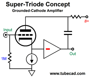
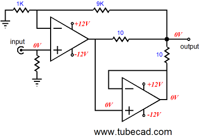
The super-triode concept uses negative feedback for reasons other than THD reduction; indeed, it might end up actually increasing the distortion that the beefy output amplifier would have produced by itself. The super-triode concept's goal was mirroring of the triode's sonic signature, creating a replica that is bigger and stronger, like a mouse that can roar like a lion. In other words, a super-triode circuit should act like a sonic magnifying glass or electronic lever. A true distortion-reducing circuit is the clever Sandman class-S topology that exploits the differential nature of a loudspeaker, which only responds to a voltage difference across its terminals.
The above Sandman class-S topology creates a virtual ground out of the bottom amplifiers. On the left we see that if the top power amplifier produces no distortion, then the bottom virtual ground offers no output signal. If, on the other hand, the top amplifier puts out some signal distortion or noise or DC offset, the bottom amplifier puts out the exact same amount of junk signal, with the result being a zero differential signal presented to the speaker, so no sound. (See posts number 20 and number 285 for more details.)
Nested Amplifiers
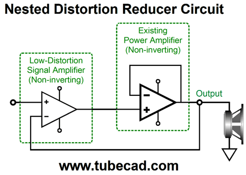
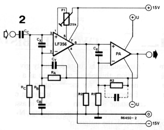
One ring to rule them all. One input amplifier to rule the output amplifier. The above circuit offers no signal gain, acting as a unity-gain power buffer. This not the usual setup. Instead, the usual arrangement is to use a low-voltage OpAmp as the input amplifier and a higher-voltage, more-powerful output amplifier, both of which create signal gain. The input amplifier can run on regulated +/-12V power-supply rails, which the beefy output applier runs on unregulated +/-50V power-supply rails. This way, the low-voltage OpAmp need only swing +/-4Vpk, while the beefy amplifier's output swings +/-40Vpk. A good example of such a design is found in Elecktor Electronics's book 303 Circuits. On pages 152 to 153, titled, "Tuning AF Power Stages," we see the following schematic. (A terrible title, by the way. I wonder how many passed it by due to the clunky title, which might have proved snazzy in the original Danish or French, but clunks and misleads in English translation.)
It looks more complicated than it actually is. The LF356 is the master amplifier and the "PA" amplifier is the slave. Potentiometer P1 sets the DC offset. The input coupling capacitor, Cc, prevents DC from leaking in and capacitor Cb allows all of the LF356's negative feedback to be applied to its DC output voltage. Capacitors, Cx & Cy are fixes, should the combined amplifiers prove unstable. The text explains how amplifier PA should use as much negative feedback as possible, which means that the input OpAmp must provide as much gain as possible. How was possible? The text states that the LF356 was only good about 5V of clean peak voltage swing. Thus, if the maximum output voltage is 100W, then the peak output voltage into an 8-ohm load would be 40V, so the output amplifier would need to amplify a 4Vpk signal into 40Vpk, or a gain of 10 (+20dB). In other words we would set the output amplifier's gain to 10 and the input amplifiers gain to 40, assuming that we expected an input signal of 1Vpk. Long ago, I discovered in a Bur-Brown data sheets the fallowing schematic that held two OpAmps in a nested-feedback configuration.
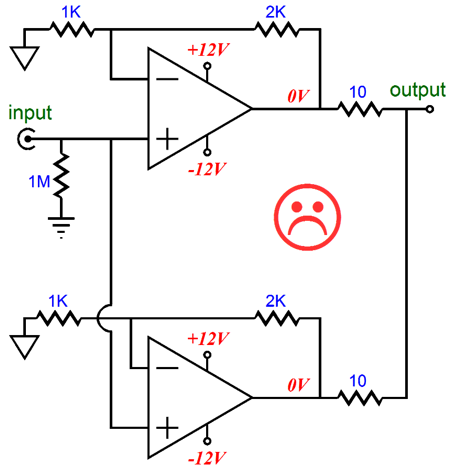
The top OpAmp is in charge. The bottom OpAmp is enslaved to the top OpAmp. The result is a substantial reduction in distortion (usually about -20dB better) over the alternative topology show below, while still allowing twice the output current to be delivered into the load impedance.
Moreover, the Bur-Brown master-slave topology offers a substantially lower output impedance, as the two 10-ohm output resistors are enclosed within the top OpAmp's negative feedback loop. The one potential problem is that the enslaved OpAmp must be unity-gain stable, not All OpAmps are. OpAmps! Are you serious? I would sooner drink fine wine with a straw than listen to OpAmps! Sure, I know that many are violently opposed to OpAmps. But not all OpAmps are solid-state, as tube-based OpAmps exist; for example, the following circuit.
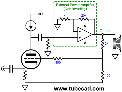
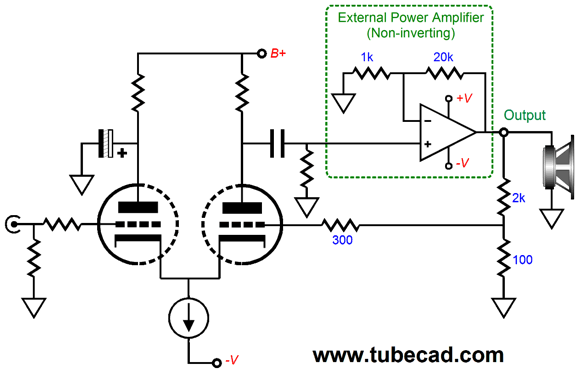
The single triode defines a non-inverting OpAmp, as the triode is configured as a grounded-grid amplifier, its input signal being imposed upon its cathode. The negative feedback is presented to its grid. The nested power amplifier, which could be tube-based or solid-state, offers a gain of 21, as (20k + 1K)/1k equals 21. The 2k and 100-ohm voltage divider resistors deliver 1/21 of the amplifier's output signal to the triode's grid. In other words, the triode's mu + 1 will set the final gain for this nested amplifier circuit. (A grounded-grid amplifier that is loaded by a constant-current source will yield a gain equal to its amplification factor plus 1.) A 6SN7 triode would deliver a gain of 21, for example; thus, the open-loop gain would equal 21² or 441. Yes, this is a super-triode design—of sorts. If we used a different voltage-divider ratio, we would get either more or less gain, which means that we would no longer be mirroring the triode's behavior. Ideally, we would want the triode to set the final gain, not the voltage-divider resistor ratio. The input impedance looks as if it should very low indeed. It isn't, in fact, due to the constant-current load at the plate. Still, the input capacitor will dismay a few readers. Here is a cathode-coupled amplifier instead.
Certainly, many more features and safety devices could be added, but this is the basic topology.
Okay, now that we have warmed mentally, we can move on to the D. Bollen distortion-reducer circuit from the Wireless World magazine from February of 1972, which I mentioned in my last post.
D. Bollen's Distortion-Reducer Circuit
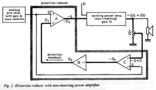
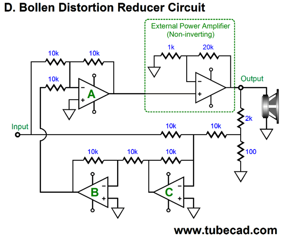
Signal amplifier, C, compares the input signal to the amplifier's output signal. If there is a difference, this amplifier delivers in an inverted form at its output. Signal amplifier, B, simply inverts amplifier A's output. Let's use some OpAmps to illustrate the scheme.
All of the additional signal amplifiers are configured as inverting unity-gain stages. If the external power amplifier produces no distortion, amplifiers B & C produce no output, as shown below.
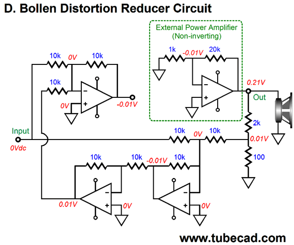
Should the external power amplifier produce a DC offset, a form of distortion, the additional signal amplifiers work to eliminate it. Let's break the connection to the external power amplifier, so we can better see the voltage relationships.
The 0.21V DC offset voltage is reduced to 10mV by the voltage divider at the output of the external power amplifier. This 10mV then gets inverted at amplifier A's output. If we connect this output to the external power amplifier's input, the DC offset disappears. Now, imagine that instead of DC offset the external power amplifier is creating harmonic distortion. The voltage divider will reduce the external power amplifier's output to the same level as the music signal source. OpAmp C will compare the music to the external power amplifier's output and its output will consists of solely the external power amplifier's distortion, as the music signal has fallen out of the equation. OpAmp B then inverts this distortion product. And, finally, OpAmp A mixes this in-phase distortion with the in-phase music signal. Okay, D. Bollen didn't use IC OpAmps; instead, he/she used four NPN transistors. Amplifier A used two, while B and C used one transistor.
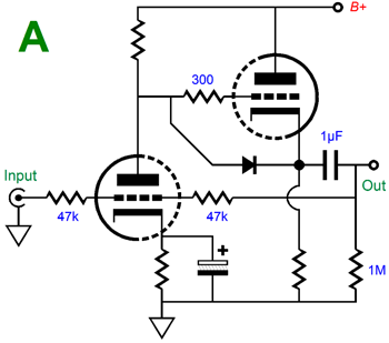
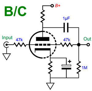
For those used to tube circuits, this schematic will look very strange indeed. Unlike triode, transistors are enhancement-mode devices. In other words, a transistor needs to see positive base voltage to conduct current. Now, if you squint your eyes, you can more easily see how triodes could replace the transistors. Let's start with the two-transistor OpAmp (A).
The input triode is configured as a grounded-cathode amplifier; the second triode, a cathode follower. The two 47k resistors set the gain to unity. OpAmps B & C can be made with just one triode configured as a grounded-cathode amplifier.
With the two 47k resistors transforms the grounded-cathode amplifier into a plate follower. Adding all three tube OpAmps into a Bollen distortion-reducer circuit creates the following design .
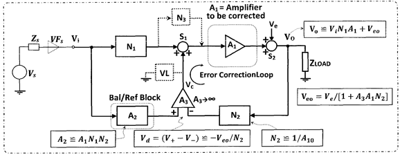
Not that bad, isn't it? Two dual triode tubes and a few capacitors and resistors. As it stands, the feedback resistor values would need to be adjusted, as the plate followers will fall slightly below unity-gain. In other words, some of the 47k resistors should be replaced with 51k or 56k resistors. No, I haven't built this translation; I haven't even simulated in SPICE yet. No time. Nonetheless, the results might prove truly interesting, as it just might radically improve the sound of an existing solid-state amplifier. John, John, just because some circuit is old does not mean that is any good. True. But before you pass judgment, check out US Patent 8686793, issued in 2014 and titled, "Amplifier device with reiterable error correction scheme with balanced negative feedback." There you will find this schematic.
It may look much different, but it is functionally the same. Some low-pass filters are added, but then the original circuit held implicit low-pass filters due to Miller-effect capacitance and the 330k series resistors. Here is a quote from the patent:
Then a bit later on in the patent, we read:
Special Thanks If you have been reading my posts, you know that my lifetime goal is reaching post number one thousand. I have 624 more to go. I should easily be able to hit post 400 this year. My second goal is to gather 1,000 patrons. I have 968 patrons to go. If you enjoyed reading this post from me, then you might consider becoming one of my patrons at Patreon.com.
//JRB
User Guides for GlassWare Software Since I am still getting e-mail asking how to buy these GlassWare software programs:
For those of you who still have old computers running Windows XP (32-bit) or any other Windows 32-bit OS, I have setup the download availability of my old old standards: Tube CAD, SE Amp CAD, and Audio Gadgets. The downloads are at the GlassWare-Yahoo store and the price is only $9.95 for each program. http://glass-ware.stores.yahoo.net/adsoffromgla.html So many have asked that I had to do it. WARNING: THESE THREE PROGRAMS WILL NOT RUN UNDER VISTA 64-Bit or WINDOWS 7 & 8 or any other 64-bit OS. One day, I do plan on remaking all of these programs into 64-bit versions, but it will be a huge ordeal, as programming requires vast chunks of noise-free time, something very rare with children running about. Ideally, I would love to come out with versions that run on iPads and Android-OS tablets.
//JRB |
And
High-quality, double-sided, extra thick, 2-oz traces, plated-through holes, dual sets of resistor pads and pads for two coupling capacitors. Stereo and mono, octal and 9-pin printed circuit boards available.
Designed by John Broskie & Made in USA Aikido PCBs for as little as $24 http://glass-ware.stores.yahoo.net/
The Tube CAD Journal's first companion program, TCJ Filter Design lets you design a filter or crossover (passive, OpAmp or tube) without having to check out thick textbooks from the library and without having to breakout the scientific calculator. This program's goal is to provide a quick and easy display not only of the frequency response, but also of the resistor and capacitor values for a passive and active filters and crossovers. TCJ Filter Design is easy to use, but not lightweight, holding over 60 different filter topologies and up to four filter alignments: While the program's main concern is active filters, solid-state and tube, it also does passive filters. In fact, it can be used to calculate passive crossovers for use with speakers by entering 8 ohms as the terminating resistance. Click on the image below to see the full screen capture.
Tube crossovers are a major part of this program; both buffered and un-buffered tube based filters along with mono-polar and bipolar power supply topologies are covered. Available as a downloadable file (4 Megabytes). |
||


| www.tubecad.com Copyright © 1999-2017 GlassWare All Rights Reserved |