| John Broskie's Guide to Tube Circuit Analysis & Design |
|
02 July 2017 Post 386 MORE
Exploiting Switcher Power Supplies, Part Two
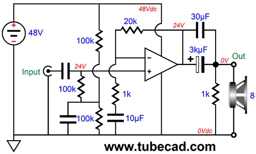
I know that many solid-state-loving audiophiles will laugh at such a puny output, but I also know that many tube-loving audiophiles—say those who own 2.5W flea-power single-ended tube amplifiers—long to hear the roar of 25W. All we need to do is split the 48V down to 24V at the input and capacitor couple both the amplifier's output and its feedback resistor string.
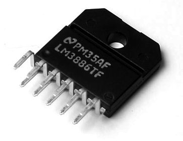
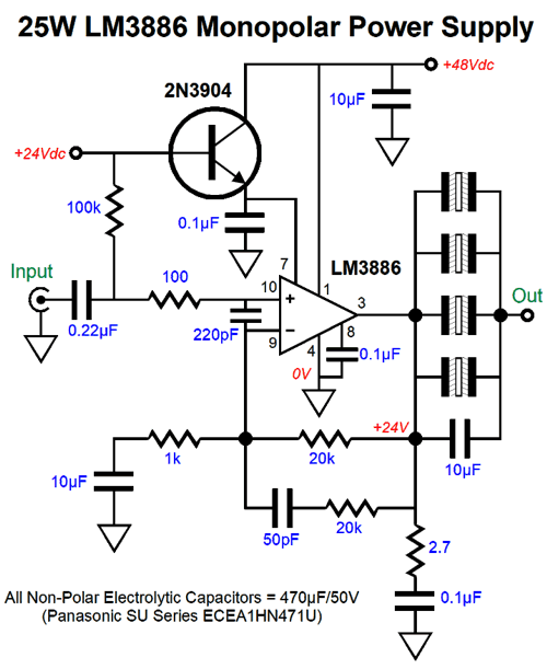
The seemingly easy solution would be to use a chip amplifier, such as the famous LM3886.
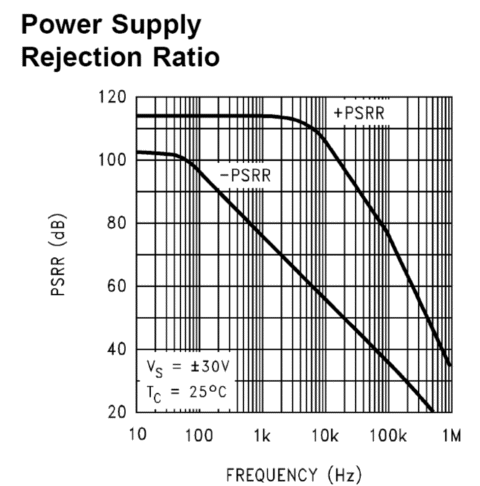
I know that many readers instinctively recoil at the thought of capacitor coupling, as they falsely conclude that the capacitors in the power supply do not count. Well, consider this, one key advantage to using a mono-polar power supply with a chip amplifier (or just about any other OpAmp) is that the amplifier's PSRR relative to its negative-power-supply pin is usually far worse. Indeed, here is the LM3886's PSRR graph.
Note that at 10kHz, the negative pin's PSRR is about 60dB worse than the positive pin's. By using a mono-polar power supply with the LM3886, only one PSRR plotline obtains, the top one, as the negative PSRR plotline has gone to infinite PSRR. Nice trick. It may sound easy, but making an LM3886 work with a monopolar power supply takes some work, as the following schematic makes plain.
The LM3996's pin 7 needs to be "grounded," which with a mono-polar power supply means low-impedance terminated into half of the single rail voltage; in the above example, 24v. Missing from the schematic is the needed two-resistor voltage divider and bypass capacitor required to create the 24V reference voltage. In addition, we could add a fuse at the B+ connection and two "catch" rectifiers at the LM3886's output, with one going to the B+ and the other terminating into ground. If we wish to use the LM3886's muting feature, then we will have to add a bit more to the schematic, as its data-sheet shows below. (Some might argue for even more added circuitry, such as an input RFI filter.)
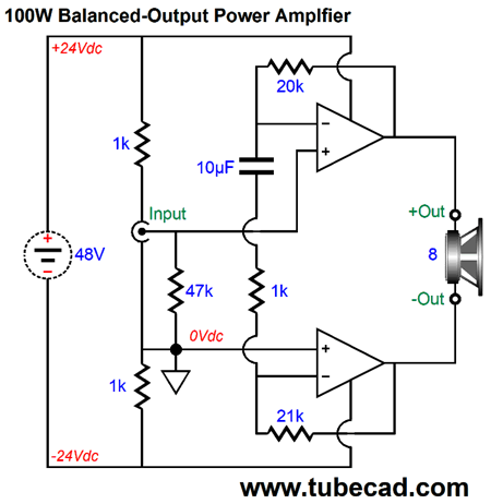
Now, keep this schematic in mind as you look at the next schematic, as each triangular amplifier symbol could/should be replaced with the more complex version shown above, but which I excluded to preserve clarity and to save my fingers.
How do we get 100W out of two 25W amplifiers? As far as each of the bridge amplifiers is concerned, the load it drives is not 8-ohms, but 4-ohms, so as one swings up to +20Vpk and the other swings down to -20Vpk, each amplifier. delivers 5A peak, the same peak current swing that a 4-ohm load would compel in a non-differential setup, not 2.5A peak an 8-ohm load draws. The speaker sees a voltage differential of 40Vpk and experiences a current flow of 5A peak, which translates into 100W. Effectively, we have doubled the peak output voltage swing that in a non-differential setup could deliver, 40Vpk, rather than 20Vpk with a 48V power-supply voltage. If the amplifiers cannot work into a 4-ohm load, however, they cannot be used to get 100W —or if they are used, they will not deliver four times the nominal 25W into a 8-ohm load. To be honest, I would not feel comfortable with using two LM3886s in this application; instead, I would prefer to use four LM3886 amplifiers. (I don't doubt that two LM3886s could deliver the needed current; I just fear too much heat for each amplifier. With four amplifiers, the heat could be spread across the length of the heatsink.)
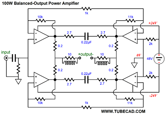
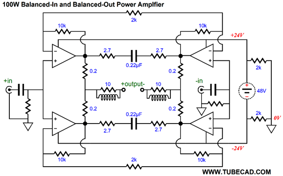
In this setup, as far as each of the bridge amplifiers is concerned, the load it drives is 8-ohms, as each individual amplifier delivers a peak current swing of 2.5A. Note the unbalanced input signal. If you have a balanced signal source, then the following is the way to hook it up. In both designs, the two-resistor voltage diver across the 48V switching power supply creates a "ground" at its center.
Note the symmetry in feedback resistor values in this setup. What if you want more power? Lots more. First of all, why would you want more power? If it is to drive a massive subwoofer, then a cool-running, but hugely powerful class-D amplifier is your best choice. As Lord Acton (John Emerich Edward Dalberg Acton, first Baron Acton, 1834–1902) might say today,
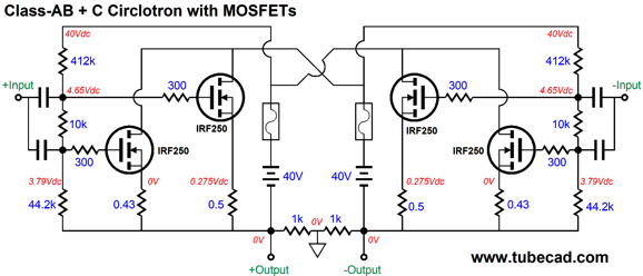
Okay, let's say that as far as you are concerned, more is more, never less. We could use two 48V switchers per channel and build a solid-state Circlotron.
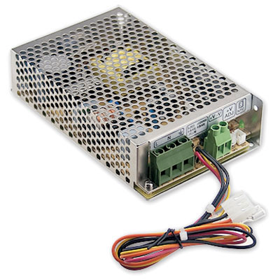
In this example, I would use the enclosed switcher power supplies that are meant to be housed in an enclosure, not a wallwart or desktop model.
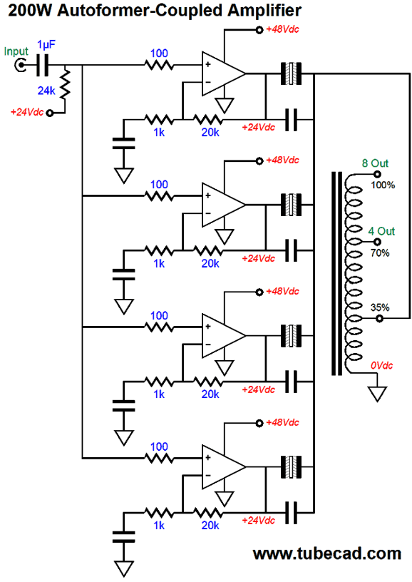
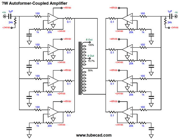
Why? If you lose contact with one enclosed switcher power supply, you will probably lose your loudspeaker as well. DC-coupled amplifiers and DC power plugs and jacks and safety do not mix. (Actually, as configured, this MOSFET-based Circlotron is fairly safe, with one floating power supply missing from action or one fuse blown.) Alternatively, we could use four LM3886s and an autoformer, with 200W being a possible result. Yes, it is possible to get 200W out of a 48V power supply. An autoformer is like half a transformer, the good half. Have you ever seen the specifications for an industrial isolation/step-down transformer? If so, you probably have seen a sentence like this one: "250W as a 230Vac to 115Vac step-down transformer; 500W as a 230Vac to 115Vac autoformer." How did the product double its output wattage? The core only saw half of the power transfer in the autoformer configuration, so twice the power is transferable before the core saturates. (See post 324 for a longer explanation of what an autoformer is and how it can be used in audio.) In other words, the autoformer will not have to be as large as you might imagine. On the other hand, since we expect bandwidth down to at least 30Hz, the autoformer must be twice as heavy as an transformer that is intended for 60Hz only use. If I remember my transformer math correctly, every time you halve the low-frequency cut-off frequency that an output transformer must extend down to, you must quadruple the core weight. For example, a push-pull output transformer that delivered 25W down to 30Hz would be the same size as a power transformer that had a 100VA rating. If you wanted full-power bandwidth down to 15Hz, then it would be the same size as a 400VA 60Hz power transformer.
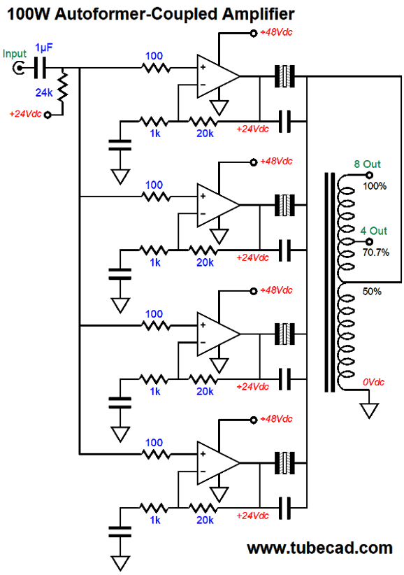
As far as each LM3886 is concerned, in the above circuit, it is working into a 4-ohm load and it is delivering 50W of power. In fact, the load impedance at the autoformers bottom tap is 1 ohm, whether the load be 4- or 8-ohms. Add all four outputs together and we get 200W into either 8-ohm or 4-ohm loads. The winding ratio requires that the 8-ohm tap sees 2.83 times more voltage than the 35% tap, which the four amplifiers work into, as this results in a 8:1 impedance ratio, as 2.83² equals 8. Once again, I would prefer to use eight LM3886s instead of just four. If nothing else, using eight will distribute the heat more evenly along the heatsink. In addition, eight would look cool. (Besides, 16 LM3886 chip amplifiers will only cost $95.20 from Mouser, far less than one 2A3.) Note that no series-output resistors are used. Why not? The output coupling capacitors effectively comprise these resistors due to their ESR (Effective Series Resistance). Also note that non-polarized capacitors are used and that each gets its own film or PIO bypass capacitor. I have a feeling that much head scratching is going on now. Let's look at another example, a 100W version, which will make for easier math.
This time, the autoformer tap is set to 50%, which means a voltage ratio of 2:1 and a current ratio of 1:2 and an impedance ratio of 4:1 relative to the 50% tap and the 8-ohm tap on the autoformer. For your homework assignment, what would be the output power of the above circuit if the bottom of the autoformer were driven by four additional LM3886 amplifiers, but in anti-phase to the original four?
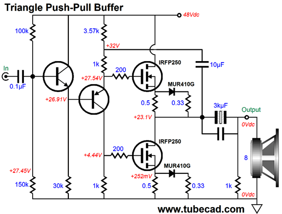
Note that all the coupling capacitors are gone. Indeed, if you are clever, you can lose four more capacitors from the circuit. What if you disdain chip amplifiers, preferring to go the discrete route? Well, if nothing else, you have my respect; and you gain control of the amplifier topology and parts. I like the idea of naked amplifiers, amplifiers that do not hold an input stage (or even a driver stage), which I refer to as a naked amplifier; a naked push-pull amplifier can even be built that would require a high-gain balanced line-stage amplifier. The naked power amplifier might offer some voltage gain or it might run just as a unity-gain power buffer, but most of the voltage gain is offloaded to the line-stage amplifier The following is an example of a unity-gain power buffer that would require up to 20Vpk signal swings from the line-stage amplifier, an easy task for most tube-based circuits.
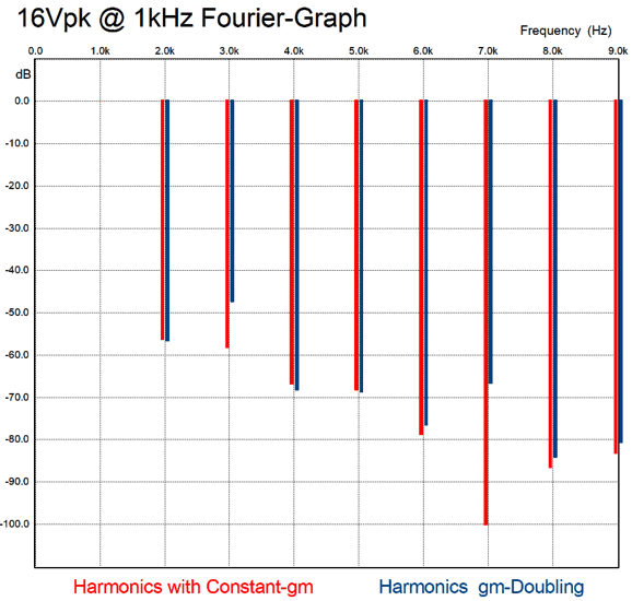
The two N-channel power MOSFETs operate in push-pull fashion. The idle current is a warm 0.5A, which delivers a 4W, class-A window of operation. The two MUR410G ultra-fast rectifiers and the two 0.33-ohm source resistors create a constant-transconductance output stage. When I show a schematic like this one to friends, these added parts irk or bewilder many. Their unease readily apparent in the question so often asked, "Do they really make a difference, or could I leave them out? A fair question based on mental discomfort, but not based on cost or added complexity, as $1 and a an extra square inch of PCB space is all that is needed. I believe that they are essential. Here is why. The following graph was generated in SPICE simulations with and without the added anti-2gm parts.
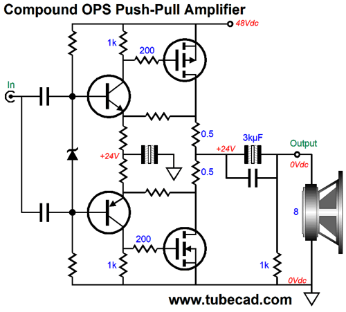
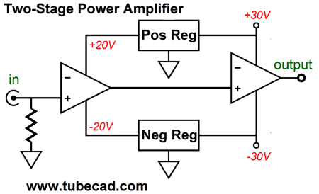
In terms of THD, there isn't much difference between the output with the added parts (0.21%) versus without the parts (0.47%). But in terms of actual odd and even harmonics, the difference is huge. For example, look at the 3rd and 7th harmonics. I know which version my ears would prefer to listen to. Another possibility would be to build a two-stage, compound amplifier that offered a low gain of 2 to 4, i.e. +6dB to +12dB.
Most solid-state power amplifiers consist of three stages; some with more than three stages; almost none with just two stages. About 40 years ago, I designed and built my two-feedback-stages solid-state power amplifiers, whose second stage looked much like the circuit above, save for some extra safety measures.
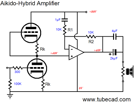
My two-stage amplifier got good reviews from friends, who found the highs to be exceptionally clean for a solid-state design; the bass, on the other hand, was universally found to be wanting in comparison to class-A amplifiers made at the time. (Perhaps, it is time to revisit this old design.) If we set the two-stage amplifier's gain to 2 (+6dB), then we can use the following Aikido circuits. Tubes at last!
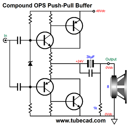
The input stage delivers a gain equal to half of the triode's amplification factor, which the solid-state, two-stage amplifier doubles, delivering the triode's mu as the final gain. By terminating the feedback resistor's capacitor into the B+ connection, we cancel the power-supply noise at the amplifier's output. Aikido mojo. See post number 141 for more details. If we replace the power MOSFETs with power transistors, then we can make unity-gain power buffer with a compound output stage.
The smaller center input transistors control the bigger top and bottom transistors, while still delivering some current into the speaker. To this circuit we can add the constant-transconductance feature by adding two rectifiers and two resistors. Indeed, given enough time, I could come up with 1,000 amplifier/buffer circuits that exploited one 48V switcher power supply. Let me use two power supplies, and the number easily doubles. Okay, here is one last use for a switching power supply. In post 354 I described the following common problem.
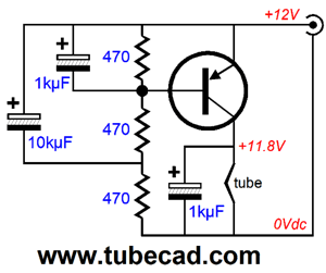
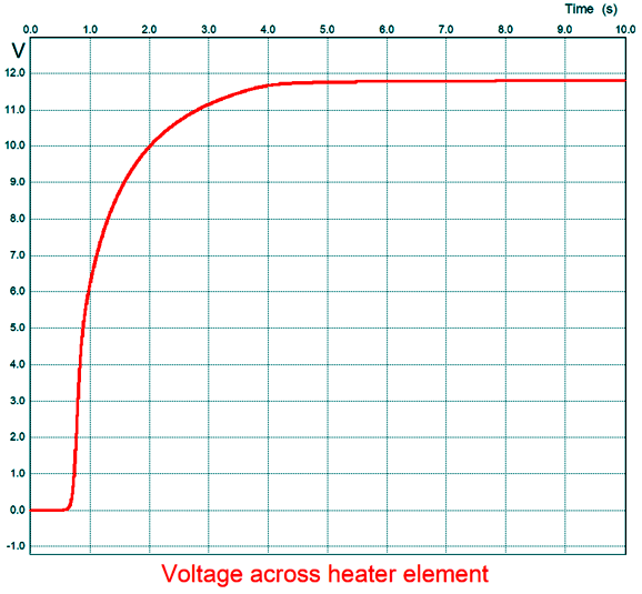
Instead of a regulated 12V power supply being powered by a 15V switcher, we can use one PNP transistor and a few resistors and capacitors to build a slow-start heater circuit.
This circuit might get pass the switcher's strict current limit, as it would ease the DC voltage into the cold heater element. Here is a SPICE simulation graph based on an ECC99 tube being heated.
Note that it took 5 seconds before the heater element got its full DC voltage.
Chromecast Update
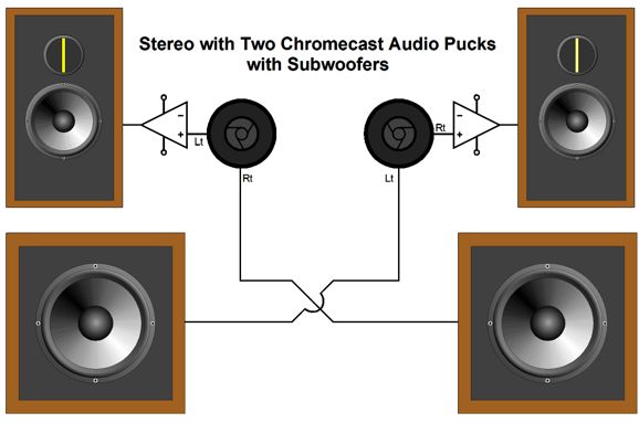
How did it sound? Well, my first impression was too bright, too thin in the bass. I then realized that I hadn't connected my powered subwoofers. Since my main power amplifiers are tube, single-ended mono-block designs and since each subwoofer contains its own power amplifier, I decided to forgo using signal splitters, so I cross-wired the outputs to the subs.
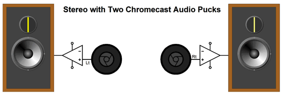
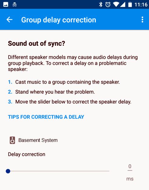
Okay, how did the system sound now? Much better tonal balance, but not perfect. The left-right balance was off, with the right channel playing louder—or, rather, as if the right speaker were about 6 inches closer. My wife has been rearranging items in the listening room, so I figured that she might have moved the speaker. I broke out the tape measurer and measured equal distances. I just couldn't imagine that two Chromecast Audio pucks could, in terms of signal volume, differ in output. Then, I remembered that the Google Chromecast app held a time alignment feature, so that you could bring two groups of cast speakers sound in sync.
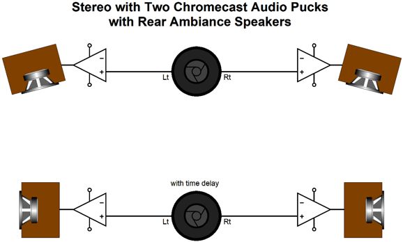
The setting was already at 0, which didn't stop me from playing with the slider. Interesting. A horrific echo can be produce with a small imposed delay. (I am actually quite familiar with this type of sound, as my fourteen-year-old son likes to play the radio and then try to play the same song on my tablet, while trying to get the two sounds to line up in time.) I returned the slider to the zero position and the two channels sounded balanced now. Many would stop here, but this is where my mind starts. All I could think of was: How could I exploit this correct-speaker-delay feature? One thought that readily came to mind was that I could set up a pair of ambiance speakers fed by a stereo amplifier and one Chromecast Audio puck.
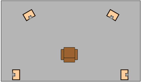
The rear speakers should point at the side walls, rather than at you. In addition, the rear volume should be much lower than the front speakers.
Here is how I set it up such a system: I begin by turning up the rear volume until I can just hear the rear speakers while the front play; then, I back off the rear volume a tad. Now, things get interesting. Play a bunch of your most familiar music and you will swear that you don't hear much difference at all. After about an hour or two, turn off the rear amplifier. Tragedy. Where did all the sound go? Why does your two front speakers now sound so threadbare, so tiny? From post 280:
Injecting a bit of time delay to the rear speakers can make your listening room sound much bigger. Another possible exploitation of the "group delay feature" might be to add powered subwoofers to a system that already uses subwoofers or speakers that do not need any help in the bass. Why? The added subs, which should be located at least three feet behind the regular speakers create an illusion of increased depth, which works well with symphonic music. Here is a quote from my article/essay Missing Sonic Controls.
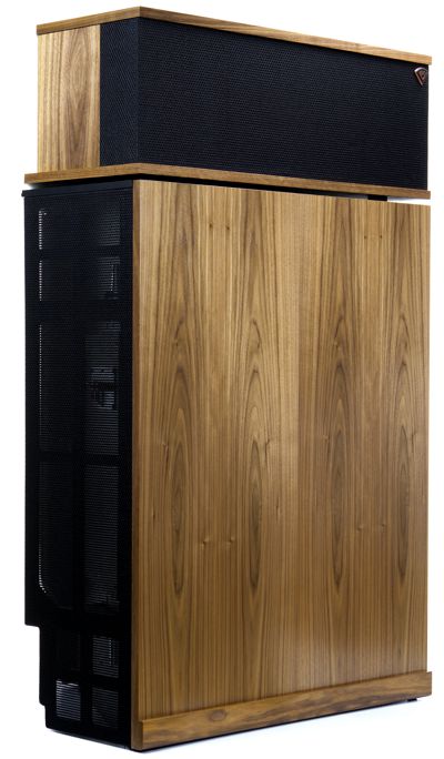
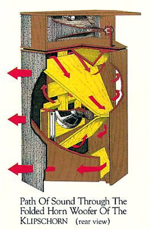
With some added time delay, the subwoofers could be placed next to your speakers—and maybe in front of them! Another possible exploitation might be to bring the famous Klipsch corner horn into time alignment.
Its three drivers are not in time alignment, as sound from its tweeter hits your ear first, soon followed by the midrange and then, much later, the woofer.
The woofer is found deep within the elaborate cabinet and its sound must travel through the many folds before emerging into the room. This always troubled me. (I used to own one Klipsch corner horn, which I used a subwoofer in high school.) I have always wanted to hear a time aligned Klipsch horn. With two Chromecast Audio pucks and two stereo power amplifiers, such a dream is much more realizable. One amplifier would feed the midrange and tweeter horns—but with a 8 or so millisecond delay. The 15 inch woofers would get the non-delayed input signals. The result might prove startling. And, if nothing else, we could easily double-blind test the setup with and without the delay; all that would be required is to slide the Google Chromecast app's group-delay-correction slider back to zero. Google provides programmers a Chromecast API toolkit, so Chromecasting can readily be added to phone and tablet apps. Here is how Google describes it.
Once we get access to what is under the hood, the real modding happens. I can imagine sending out two pairs of balanced signals to two Chromecast Audio pucks, so that each puck would put out one channel's balanced signals, rather than left and right unbalanced signals. Or, I can imagine that a digital crossover could be performed and the filtered signals sent out to two pucks, one puck for high-pass and one for low-pass signals.
Next Time
//JRB
If you have been reading my posts, you know that my lifetime goal is reaching post number one thousand. I have 614 more to go. My second goal is to gather 1,000 patrons. I have 959 patrons to go. Of course, I would be thrilled to just have 100 patrons, but goals are worth having. If I were a betting-man, I would place my bet on my reaching the 1,000 patron goal first, as I have a hard time believing that I have already posted 386 times. How is that possible? I would never have bet on that happening. If you enjoyed reading this post from me, then you might consider becoming one of my patrons at Patreon.com. The more patrons that support me, the more time I can devote to creating these posts.
Next Time
User Guides for GlassWare Software
For those of you who still have old computers running Windows XP (32-bit) or any other Windows 32-bit OS, I have setup the download availability of my old old standards: Tube CAD, SE Amp CAD, and Audio Gadgets. The downloads are at the GlassWare-Yahoo store and the price is only $9.95 for each program. http://glass-ware.stores.yahoo.net/adsoffromgla.html So many have asked that I had to do it. WARNING: THESE THREE PROGRAMS WILL NOT RUN UNDER VISTA 64-Bit or WINDOWS 7 & 8 or any other 64-bit OS. I do plan on remaking all of these programs into 64-bit versions, but it will be a huge ordeal, as programming requires vast chunks of noise-free time, something very rare with children running about. Ideally, I would love to come out with versions that run on iPads and Android-OS tablets.
//JRB
|
|
Kit User Guide PDFs
Only $12.95 TCJ My-Stock DB
Version 2 Improvements *User definable Download for www.glass-ware.com |
||


| www.tubecad.com Copyright © 1999-2017 GlassWare All Rights Reserved |