| John Broskie's Guide to Tube Circuit Analysis & Design |
05 September 2016 Post 394
Special Thanks If you have never produced a technical white paper or written an article on electronics, you probably cannot imagine how much time and effort is required to produce one of my posts. My lifetime goal is reaching post number one thousand. I have 606 more to go. And with only eight more to go, I should easily be able to hit post 400 this year. Four hundred posts! The mind boggles. My second goal is to gather 1,000 patrons. I have 948 patrons to go. If you enjoyed reading this post from me for the last 18 years, then you might consider becoming one of my patrons at Patreon.com. It would make a big difference to me. Thanks.
Bi-Wiring Part Two
Well, while thinking about bi-wiring, I wondered if there wasn't some special advantage that might accrue from our tube power amplifiers using an output transformer, particularly an output transformer that offers many output impedance taps, for example, 16-, 8-, and 4-ohm taps. The output transformer was a great invention, as it allowed amplifiers to deliver a consistent power output into 4-ohm, 8-ohm, and 16-ohm loudspeakers.
Consistency is a much valued attribute. Remember the old joke about the minister admonishing his congregation that unless they had something good to say about someone they should say nothing. One clever parishioner asked the minster what he had to say about Satan. Undaunted, the minster replied, "He is consistent." Amplifiers that do not make use of an output transformer, such as tube OTL amplifiers and most transistor amplifiers, deliver inconsistent output power, depending on the load impedance: solid-state amplifiers delivering more power into 4-ohm loads and less power into 16-ohm loads, while tube OTL amplifiers deliver less power into 4-ohm loads and more power into 16-ohm loads. Why the contrary performance? The solid-state amplifier is voltage limited, not current limited; the opposite for the tube OTL amplifier.
Years ago, I had a friend who worked in a high-end audio salon. The store had to replace their reference tube power amplifier with a solid-state behemoth, as the store new reference speaker was the Apogee Scintilla, whose 1-ohm impedance was too low for the tube amplifier. I pointed out that the output transformer could couple with other impedances than just 16, 8, and 4 ohms. Blank stare. I explained how a speaker could be attached between the 16-ohm and 8-ohm taps or between the 8-ohm and 4-ohm taps. Raised eyebrows. I went on to say for example that the output transformer expected see a 16-ohm load across its entire secondary, so the 50% tap could drive a 4-ohm speaker, as the 50% tap resulted in a doubling of the winding ratio between primary and secondary, which results in a quadrupling of the impedance ratio between primary and secondary. Thus, the 4-ohm load was the equivalent to the 16-ohm load in terms of primary impedance. All that was left for us was to calculate the load impedance needed to produce the same primary impedance when attached across the 8-ohm and 4-ohm taps. He said to me, "You make it seem as if it's just math. You do not even know what the primary impedance is." I didn't need to know what the primary impedance was and, yes, it is just math. All of electronics is just math. Capacitors, inductors, and resistors—all embody strict mathematical relationships, and so, too, output transformers. The 16-ohm tap presents 100% of the secondary winding; the 8-ohm tap, 70.7%; and the 4-ohm tap, 50%. Between the 8-ohm tap and the 4-ohm tap, we see 20.7% of the winding. Thus, to find the required load impedance to ensure the same primary impedance we multiply 16 by 0.207² and get 0.685 ohms. To get the require load impedance between 16-ohm and 8-ohm taps, we multiply 16 by 0.293² and get 1.37 ohms. I told my friend that he should try the latter connection, as the secondary winding itself offered some wire resistance as did the speaker cables, bringing the total close to 1.37 ohms.
His response was, "You know, John, what you are saying is entirely outside of what is conventionally understood?" My answer, "Sure. Why else would I bother saying it?" Did his store try my suggestion? I don't know. The next time I showed up, the new reference speaker was from Wilson Audio, a nice 8-ohm design, so the tube amplifier was back in play. The punchline here is that we should try to think outside the 8-ohm and 4-ohm box. Working on the assumption that large-valued, high-quality coupling capacitors and inductors cost a small fortune, it behooves us to try to use the smallest values we can in a speaker's crossover. Here an output transformer can make real value savings. For example, if we built a two-way speaker, whose tweeter was 3dB more efficient than the woofer, then we could use the 16-ohm tap and an 8-ohm padding resistor to bring the tweeter's output in line with the woofers, which would halve the crossover capacitor value.
Note that the 8-ohm padding resistor imposes a -6dB reduction of SPL, but the 16-ohm tap offers a +3dB boost in SPL, so the tweeter sees a net -3dB cut. And if we used a 4-ohm woofer, we could attach it to 4-ohm tap and an inductor with half the value that an 8-ohm woofer would require, while still presenting the same primary impedance. (The crossover shown is a simple 1st-order design, but a 2nd or 3rd or 4th order crossover could be used.)
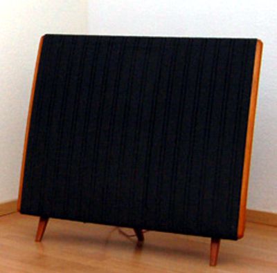
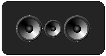
One popular speaker driver arrangement is the Joseph D'Appolito configuration, where the high-frequency driver sits between two low-frequency drivers. Mind you, he didn't invent this setup, as the old Quad model 57 held two low-frequency ESL panels bracketing a high-frequency ESL panel (as did several other speakers), but he did point out some advantages that accrue from this arrangement.
Well, unless you are using two 16-ohm woofers or two 4-ohm woofers, you will end up with a 4-ohm woofer section. (There is this crazy prejudice against placing two offers in series, as the fear of a ruined damping factor looms big in some minds, needlessly.) Well, with an output transformer, we can use two 8-ohm woofers in parallel, as long as we attach them across the 4-ohm and ground taps.
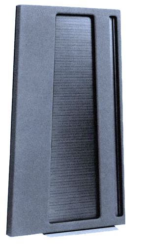
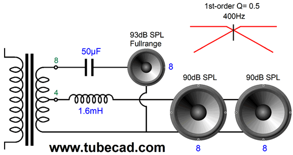
One speaker that I have longed to build is a faux old Quad: a dipole that held three full-range drivers in a D'Appolito arrangement, or is old Quad arrangement, with a low crossover frequency of 400Hz, close to the Quad 57's 500Hz crossover point. Why so low? Wavelengths. Take the speed of sound in inches, about 13,536 in/sec, and divide it by the crossover frequency. In this example, we get 33.8 inches. Ideally, the two outside low-frequency driver centers must be closer than half this distance.
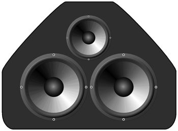
In fact, the following triangle arrangement might prove even better, as it keeps the three driver centers as close as possible.
Assuming that all three drivers are 8-ohm units, we could place the two low-frequency drivers in series and attach them to the 16-ohm tap. The math gets interesting here. The 16-ohm tap offers 1.414 times more signal than the 8-ohm tap, so the two drivers would each see half of the this voltage, or 0.707 as much as the 8-ohm tap puts out, resulting in a -3dB attenuation. We have, however, effectively doubled the radiating surface with two drivers, so we gain a +6dB boost, resulting in a net +3dB boost in this arrangement. Thus, two 90dB low-frequency drivers could be mated with a 93dB full-range driver.
Alternatively, we could place the two 8-ohm woofers in parallel, reducing the inductor value as a result.
What about three-way speakers? We could use the 16-ohm tap for the tweeter, the 8-ohm tap for the midrange, and the 4-ohm tap for two 8-ohm woofers in parallel.
The woofers see -3dB less signal than the midrange, but gains +6dB due to being paralleled, so a net gain of +3dB. Thus, we can use a 93dB tweeter with a 90dB midrange with two 87dB woofers, while using the lowest-valued capacitors and inductors.
Hybrid Bi-Wire Ideas
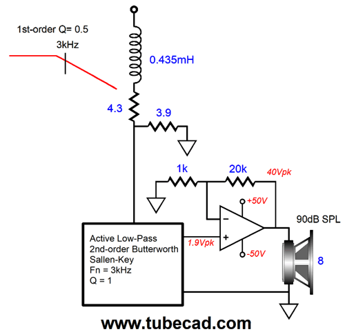
Think about it: if a tweeter is getting many watts of power from the amplifier but is only putting out weak SPL, where does the excess energy go? Remember that energy cannot be destroyed, only converted into another format. In the case of the tweeter, the wasted power becomes heat. Not good. I remember reading that the equivalent 1 watt of electrical power results in an SPL of 127dB, which equaled of acoustic power. In other words, 1 watt goes in and 1 watt comes out, so no heat. Thus, an SPL of 110dB will give rise to far less heat than an SPL of 90dB. Moreover, a driver with an efficiency of 110dB will put out the same SPL with 1 watt that a driver with an efficiency of 90dB will put out with 100 watts of power. Thus, you can see how a flea-power tube amplifier and horn tweeter would make a great pairing. What about the woofer? Since 100W solid-state power amplifiers are no big deal, we can use a 90dB woofer with one.
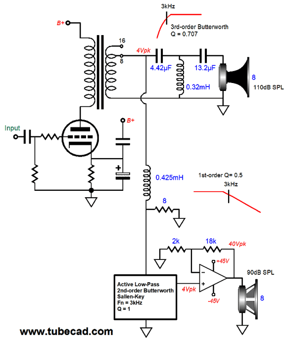
Note that the tweeter is quite safe, as the output transformer will not pass DC voltage and the two capacitors protect the tweeter; in addition, the flea-power tube amplifier cannot put out enough power to burn out the tweeter. (When bi-amping, in spite of using an active crossover, always place a capacitor in series with the tweeter. Why? A broken ground connection at the RCA jack can induce a huge hum signal that will burn the un-capped tweeter to toast.) Also note that the solid-state power amplifier offers a gain of ten, the inverse of the output transformer, so when the tweeter sees 4Vpk of signal (1W of power), the woofer will see 40Vpk (100W of power). What if the solid-state amplifier comes with a gain different from 10? No problem. A common amount of gain is 21, the result of using 1k and 20k feedback resistors.
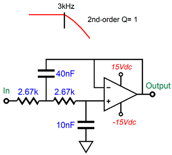
The 0.435mH inductor is loaded by 8.1 ohms and a tad less than half of the signal is passed on to the solid-state amplifier with a gain of 21, whose output equals 10 times what the tweeter sees. The result is equal SPL from both drivers, in spite of a super-efficient tweeter and a low-efficiency woofer. A medium sized enclosure could be used, if either bass reflex or acoustic-suspension loading is used on the woofer. (Transmission-line loading will require a much larger box, but will deliver far better sound.) By the way, I was once asked if I could design a super-efficient speaker that went down to 20Hz and was super small. My answer was that I couldn't; in fact, no one could, as the three attributes were mutually exclusive; I explained how he could get any two, but not all three. He didn't believe me, as others had claimed that they could design such a speaker. Just another example of my saying something entirely outside of what is conventionally understood. In other words, with the 90dB woofer, we do gain something: we can get a smaller speaker enclosure and decent low-frequency response. What is inside the box labeled 2nd-order active crossover.
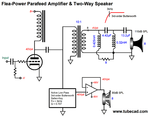
Part of the appeal of this arrangement is that we are getting some super-triode mojo. The solid-state power amplifier gets its input signal from the flea-power amplifier's output, not the original signal source, so the tube flavor is passed along, as could be the soft clipping of the tube amplifier, if the solid-state power amplifier is more powerful than it would strictly need to be.
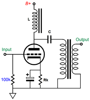
The above tube amplifier topology is a single-ended para-feed, where the plate is loaded by an inductor, and the output transformer is capacitor coupled to the plate. Since the output transformer sees no sustained DC current flow, it need not hold an air-gap and its core can be made from nickel. The inductor, however, cannot be just any junk-box choke; instead, it must be a high-quality inductor, which are both rare and expensive. Since only 40 volts of peak plate voltage swing is needed, we could use a solid-state constant-current source in place of the inductor. Let's apply this topology to our design.
The output transformer's winding ratio of 10:1 implies an impedance ratio of 100:1, so the 8-ohm horn tweeter is reflected as 800 ohms by the primary. A low-rp output triode should be used, such as the 6C33 or several 2A3s in parallel. If the winding ratio is higher, we will end up with too much signal for the buffer; the workaround would be to use a two-resistor voltage divider to reduce the signal voltage before going into the active filter. Speaking of the active filter, 40V of signal is hot and a high-voltage OpAmp, such as the OPA445, will be needed, but at least it can run off the buffer's power supply. The output transformer works into both the 3rd-order Butterworth high-pass crossover and a 1st-order low-pass crossover that is loaded by an 8-ohm power resistor. Why? The secondary needs to see a constant 8-ohm load, or a shelving tilt of the frequency response will occur, where the lows get more gain than the highs. The unity-gain power buffer that drives the woofer cannot be an LM3886, alas, as this chip amplifier is not unity-gain stable. Chip amplifiers from Analog Devices, however, are stable at unity gain. I would prefer to build my own discrete unity-gain buffer. Here is one possibility.
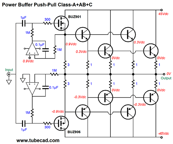
No feedback other than local degenerative feedback is used. Another possibility is the following design.
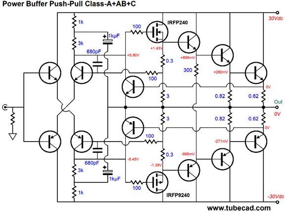
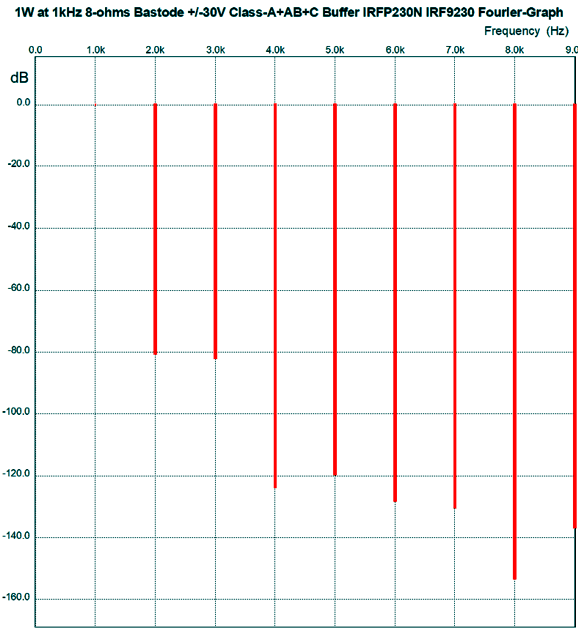
Bastode input stage followed by a constant-transconductance output stage: class-A + AB + C. With an 8-ohm load, the MOSFETs never cut off, while half of the output transistors are completely cutoff at idle and the other half run in class-AB. This buffer enjoys an auto-bias feature that is made possible by the class-A running of the two MOSFETs. As shown, this power buffer will only put out about 40W, not 100W, as the +/-30V power-supply rails set a power limit. To get 100W, we would need +/-45V rails (more would be welcome) and add four more output transistors. Here is the SPICE-generated Fourier graph for 1W of output at 1kHz.
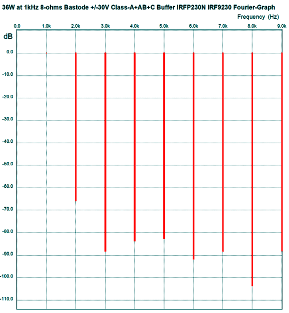
Now the graph for 36W of output at 1kHz.
Not bad. Note the reduced 3 rd harmonic.
//JRB
User Guides for GlassWare Software Since I am still getting e-mail asking how to buy these GlassWare software programs:
For those of you who still have old computers running Windows XP (32-bit) or any other Windows 32-bit OS, I have setup the download availability of my old old standards: Tube CAD, SE Amp CAD, and Audio Gadgets. The downloads are at the GlassWare-Yahoo store and the price is only $9.95 for each program. http://glass-ware.stores.yahoo.net/adsoffromgla.html So many have asked that I had to do it. WARNING: THESE THREE PROGRAMS WILL NOT RUN UNDER VISTA 64-Bit or WINDOWS 7 & 8 or any other 64-bit OS. One day, I do plan on remaking all of these programs into 64-bit versions, but it will be a huge ordeal, as programming requires vast chunks of noise-free time, something very rare with children running about. Ideally, I would love to come out with versions that run on iPads and Android-OS tablets.
//JRB |
Kit User Guide PDFs
And
High-quality, double-sided, extra thick, 2-oz traces, plated-through holes, dual sets of resistor pads and pads for two coupling capacitors. Stereo and mono, octal and 9-pin printed circuit boards available.
Designed by John Broskie & Made in USA Aikido PCBs for as little as $24 http://glass-ware.stores.yahoo.net/
The Tube CAD Journal's first companion program, TCJ Filter Design lets you design a filter or crossover (passive, OpAmp or tube) without having to check out thick textbooks from the library and without having to breakout the scientific calculator. This program's goal is to provide a quick and easy display not only of the frequency response, but also of the resistor and capacitor values for a passive and active filters and crossovers. TCJ Filter Design is easy to use, but not lightweight, holding over 60 different filter topologies and up to four filter alignments: While the program's main concern is active filters, solid-state and tube, it also does passive filters. In fact, it can be used to calculate passive crossovers for use with speakers by entering 8 ohms as the terminating resistance. Click on the image below to see the full screen capture.
Tube crossovers are a major part of this program; both buffered and un-buffered tube based filters along with mono-polar and bipolar power supply topologies are covered. Available on a CD-ROM and a downloadable version (4 Megabytes). |
||


| www.tubecad.com Copyright © 1999-2017 GlassWare All Rights Reserved |