| John Broskie's Guide to Tube Circuit Analysis & Design |
29 October 2016 Post 400
Post 400 (or I Am 40% There) Now, admittedly, our hundred blog posts does not set a record, as many have made over 400 blog posts. Tom Woods, has made over 1,000 podcast posts, each about half an hour long. Impressive, certainly, but the Guinness World Record went to Darren Murph, who made 17,212 blog posts in four years for Engadgets.com, which I assume proves the productivity boost derived from paying by the piece, rather than the hour. Thus, my puny 400 posts do not seem that impressive in comparison. On the other hand, if my post didn't run so long (this post is over 4,000 words) and contain so many subsections (this post contains seven), each of which would certainly qualify as a good-sized blog post, I would have surpassed Mr Woods' total, but not Mr Murph's. This raises an interesting question: Why post at all? In other words, why would anyone bother to write posts and why would anyone want to read them? As I see it, a blog post (of any kind), should reveal some tacit or secret or novel knowledge, rather than obvious or explicit knowledge. For example, posting—each day—a different word and its dictionary definition—as they are alphabetically ordered in a dictionary—would make for a poor blog post; but posting, each day, one special word that most do not use, or do not use correctly, might make a fun read, particularly if the post went beyond the dictionary's definition by further refining and explicating the word and offering interesting quotes of the word in use by the best writers—otherwise, why bother reading this blog, when reading the dictionary directly would be just as informative and just as boring. In other words, if insider knowledge or juicy gossip or truly individualist mutterings or refreshingly new ideas are not part of the show, a blog post is a poor entertainer. This explains why blog posts are read, but what about the writer's motivation? The two usual suspects in any human endeavor are greed and vanity. For 99.9% of blogs, we can safely rule out greed, as few bloggers are paid for their output. Vanity, on the other hand, plays a leading role, no doubt. What could be grander than a free vanity press, as it is fun to see one's name up in pixels. I have known at least two bloggers, however, who both put as much effort into each of their posts as I do, but who have fewer than 50 readers. While their vanities would be ten times more tickled with 500 readers, it is unlikely that their mildly-tickled vanities can entirely explain why they exert so much effort into each post they make. (One of them told me that this is how he talks to his son, as his son lives in another state and reads his father's every post. If his son lived with him, would he need to post? Sometimes, we can only talk directly by seemingly talking to everyone.) So, what could be another reason for blogging? In my case, this website forces me to write, both the posts and the replies to email prompted by the posts. Writing is thinking's best friend. When we write expository prose, we force our otherwise bent minds into linearity. A long-held belief that we would stake our lives upon might be revealed to be far more suspect than we had imagined prior to writing it down. When we write, we must not only convince others, but ourselves. Thus, we must resort to logic, common sense, analogy, and evidence. In contrast, those who don't write, get off easy, as the silliest notions can flourish in their minds unchallenged. In addition, I created this blog because I didn't want all the circuits slip from my pencil tip into notebooks and scraps of paper and disappear. Many times, I have turned over an old envelope and discovered some interesting circuit that I had drawn on its backside. And if I hadn't turned the envelope over, it would have remained forgotten. In other words, this website is like a notebook that I can access just about anytime and anywhere. (You cannot imagine how many times I have used Google to find one of my own circuits that I had posted here.) Being 40% there, with THERE being post 1,000, affords mixed emotions. The thought of writing 600 more posts is daunting in the extreme, but the triumphal feeling of having written 400 posts warms the soul. Believe me, if I make it to post 1,000, I will certainly have that emblazoned on my tombstone.
Special Thanks to the Special 61
If you have never produced a technical white paper or written an article on electronics, you probably cannot imagine how much time and effort is required to produce one of my posts. My lifetime goal is reaching post number one thousand. I have 600 more to go. My second goal is to gather 1,000 patrons. I have 939 patrons to go. At some moment in time, I would see my number of posts intersect with my number of patrons. If you enjoyed reading this post from me for the last 18 years, then you might consider becoming one of my patrons at Patreon.com. It would make a big difference to me. Thanks.
Electrostatic Speaker Ideas
Electrostatic Subwoofer?
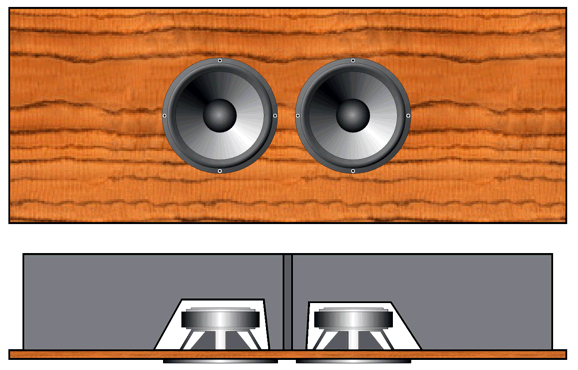
Viewed as a capacitive load, an electrostatic loudspeaker would be better suited to low frequencies, not high-frequencies, at least as far as the typical power amplifier was concerned. This got me thinking about building an electrostatic subwoofer. Yes, I know the idea sounds crazy. At the time, I had built several dipole loudspeaker systems and I loved the no-box sound. (I still do.) I didn't like, however, the discontinuity between open-sounding dipoles and lumpy-sounding sealed-box and ported subwoofer enclosures. At the same time, I had to use a subwoofer, as the dipole's bass dropped off at too high a frequency. Well, why not build a dipole subwoofer. My original idea was to use two 15in woofers, one for each channel as I didn't want mono bass, on a seven-foot wide wood panel that was 32 inch tall. (I had found a source of workbench table tops made of industrial-strength press-board, not the cheap stuff, but 1.25in thick board made of fine wood particles bound together with epoxy-strong glue; heavy beyond belief.)
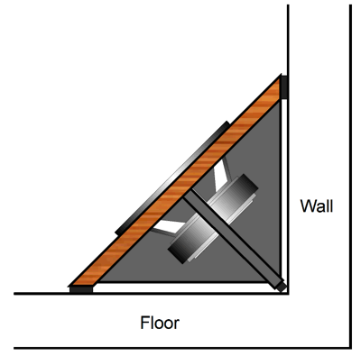
My idea was that the sub-dipole would rest at a 45 degree angle at the corner form by where the floor met the wall, so the dipole would rest in between the dipole satellites. Nothing other than gravity and friction would hold them in place. My plan was to run long strips of half-inch-thick felt on the sub-dipole's edges. I also planned on adding some wood braces to the keep the wide panel from flexing. The rear sound wave would still cancel with the front sound wave at the dipole's sides, but my hope was that I would hear enough of the bass directly in front to be happy.
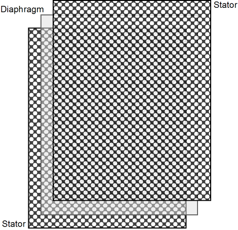
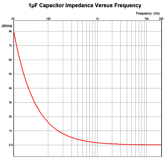
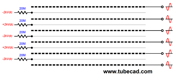
But after hearing the electrostatic loudspeakers, I wondered about how an electrostatic subwoofer could be built. As I saw it, this idea had merit, as expensive step-up transformers would not be needed, as a cheap 117Vac to 6.3Vac power transformer offered a 1:18.6 voltage ratio, besides the sub-dipole only needed to go up to 100Hz, so wide bandwidth was not an issue. In addition, a much bigger stator to diaphragm spacing could be employed, making construction easier; and the high capacitance would not impose a low impedance at frequencies below 100Hz, just the opposite. So, how did this idea turn out? It didn't, nor did the two 15in woofers dipole. Why not? I bought a single used Klipsch horn, which I used as my subwoofer. So, was my idea of building an electrostatic subwoofer totally crazy? As I had originally envisaged it, maybe. But what if we do not use the electrostatic driver in a dipole enclosure? What if we used a sealed box instead? Here is what I have in mind, we make a thick sandwich out of stator-diaphragm-stator-diaphragm-stator-diaphragm-stator… with alternating + & - connections to the stators and alternating positive and negative polarizing voltages for the diaphragms, so all the diaphragms move in phase.
The result would be that the outermost diaphragm would move the furthest, while the deepest inset diaphragm would move the least, constrained as its motion would be by the trapped air in the sealed enclosure. Indeed, we could use staggered spacing between stators and diaphragms, with the outside set being the largest apart, while the inside set was the closest together. Once again, a cheap step-up transformer would be employed and the high capacitance would become a feature, as it would be used to define a low-pass filter by placing a resistor in series with the sub-electrostatic loudspeaker, so the load impedance could only fall to the series resistor value, but not lower. To crossover at 100Hz with an 8-ohm series resistor, the capacitance would have to equal 199µF, which assumes that the resistor appears on the step-up transformer's primary; if it appeared on the secondary side, the resistor would have to be a much higher in value, while the electrostatic capacitance could be much lower, yet still impose an 8-ohm load on the power amplifier. If the transformer's voltage ratio were 1:20, then its impedance ratio would be 1:400, so a 3,200-ohm resistor could be used and the electrostatic capacitance would only need to be about 500nF (or o.5µF).
Single-Ended electrostatic
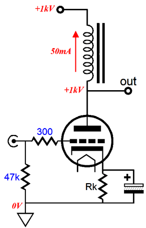
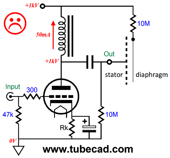
When I first read about the single-ended electrostatic distortion, my mind instantly thought about using a single-ended triode power amplifier, phased correctly, so the two nonlinearities could cancel. Triodes are easier to turn on than they are to turn off, which gives rise to the strong 2nd harmonic distortion signature. If we got the phase relationship wrong, the two nonlinearities would add, not cancel. Here is an example of getting the phase wrong.
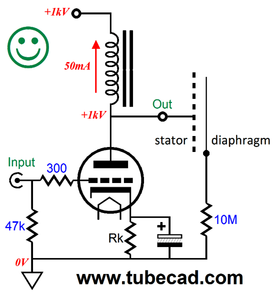
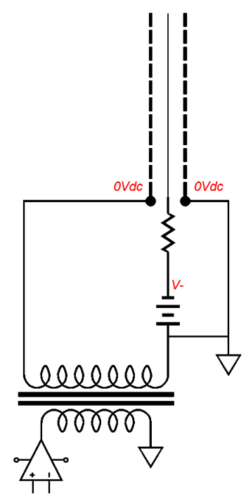
The triode can pull down its plate voltage more readily than it can let go off the plate voltage. The single-ended electrostatic speaker's diaphragm prefers moving towards the stator, rather than away from it, which the lower plate voltage will compel, so the two distortions positively combine to make more distortion. The workaround is to apply a negative polarizing voltage to the diaphragm, not a positive voltage.
Now when the plate swings negatively, the diaphragm moves away from the stator; and the two distortions subtract, rather than add together. By the way, I know many owners of horn loudspeakers who love their negative-feedback-free, flea-power, single-ended amplifiers. My guess is that the number of these audiophiles would double, if they knew about phasing. How so? The horn-loaded speaker comprises a similar non-linearity. The driver looks into the horn's throat, which presents a high resistance, as the horn is an acoustical lever (type 2 lever) and fulcrum, with the driver located at the hard-to-move side. In an attempt to equalize the high horn input resistance, the rear of the driver is loaded by a compression chamber, a small volume of trapped air. This works, sort of. The problem is that the horn input resistance is linear, while the compression chamber's impedance is reactive, i.e. non-linear. This results in the horn-loaded loudspeaker giving rise to a strong 2nd harmonic distortion. Now, if the single-ended power amplifier and the horn-loaded loudspeaker are phased correctly, the two nonlinearities will tend to cancel; phased incorrectly, they add.
Even if you run your horn loudspeaker with a push-pull power amplifier, one that contains a global negative feedback loop, phasing will still prove important. Why? Many musical instruments produce asymmetric waveforms. For example, the piano's initial positive pulse exceeds its complementary negative pulse. What makes things difficult when it comes to phasing is crossovers, which will skew phase up and down along the audio band. Another single-ended electrostatic loudspeaker idea would be to use two stators, as in the conventional push-pull electrostatic speaker, but only drive one stator. Why? Single-ended operation, but mitigated by the additional stator.
The advantage is that low-diaphragm tension could be employed and the speaker would still produce ear-pleasing 2nd harmonic distortion.
Electrostatic Frequency Doubler Tweeter
In other words, when the signal swung positive, the diaphragm moved closer to the stator; when the signal swung negative , the diaphragm moved closer to the stator. An input signal of 100Hz went in and 200Hz came out of the electrostatic loudspeaker. With the polarizing voltage in place, the diaphragm moved back and forth; 100Hz in, 100Hz out. Okay, so here is my brilliant-slash-flawed idea: we build a small single-ended electrostatic tweeter that doesn't hold a polarizing voltage and that crosses over at 22kHz and goes out to 50kHz. Why? Harmonic restoration. CDs run out of high-frequency content at one half the sampling rate, which is 44.1kHz. But we actually only get high-frequencies up to about 20kHz, as super-steep low-pass filters are employed. Now, if this frequency-doubling tweeter crossed over at 10kHz, it would not put out any 10kHz signal, but 20kHz signal. The doubling would go all the way up to 40kHz with a CD (or any 16-bit, 44.1kHz data stream), filling in the missing harmonics. Would this make a difference? And if it did make a difference, would the difference be a positive one? I don't know. Let's build one and find out. I remember an audiophile buddy telling me about the audition of his friends $$$ five-way loudspeaker that held a super-tweeter that crossed over at 20kHz. The group of audiophile assembled queried the necessity of the super tweeter. The loudspeaker also held L-pads for each driver, so a test was carried out. All the speaker drivers other than the super-tweeter were turned off. Various LPs were played; no one heard a thing; a thunderous silence resounded in the room. So, all the the other drivers were turned back on and the listening session resumed. One fellow pointed out that they should perform a follow-up test: turn off the super-tweeter and hear what happens. Everyone heard its absence and mourned it not being turned on. So how do we square these contradicting results? I remember reading that a leading university (I believe it was Stanford) conducted research on behalf of the Pentagon to find out how it was that soldiers could still determine the direction of gunfire, while wearing heavy-duty earplugs. The theory was that supersonic shock waves traveled through the brain and the brain used the directional information to locate the sound source. (While you are at it, check out TCAPS. And fasten your mental seatbelts before following this link. Amazing. Reminds me of the earth's magnetic field and the sun's radiation.) I also remember reading of an interesting experiment conducted in England decades ago, wherein a live musical signal feed was presented to super-wide-bandwidth loudspeakers in front of a group of listeners. A variable low-pass filter was then adjusted up in frequency until the group could no longer reliably predict the filter's presence. The result was, if I remember correctly, that bandwidth out to 27kHz was needed. At the 2017 RMAF, I listened to a loudspeaker with two tweeters, one above the other, with the top one being smaller. The smaller one's crossover frequency was 25kHz. I asked the rep if it made any difference. He told me that I need only place my hand over the super-tweeter to hear the difference. I did and I did. Of course, we could create a frequency-doubling circuit or one of my harmonic-restoration circuits and use a ribbon tweeter instead.
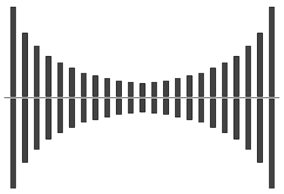
Stator as An Asset, Not Liability What if we could turn the getting in the way into a feature, instead of a bug? In other words, what if we purposely wanted the stator get in the way of the sound? My idea here is that we could use the stators as sonic lenses. Yes, Beveridge did employ an acoustical lens, but after the stator. My suggestion is that the stator and lens could be one. Imagine an array of long rectangular aluminum strips of varying widths, but all the same length, arranged vertically. Here is the view from the top:
As the sound leaves the diaphragm it encounters less resistance in the middle and progressively more as it nears either side. The result is a bending of the wave-front to a more cylindrical shape. In addition, this stator structure, symmetrically used on both sides, would create and vastly more rigid dipole enclosure. Another possible lens could be made by using the rectangular rods of metal, but alter the spacing between them:
And, of course, we could do both. (Note the rounded corner on the metal rods, which I failed to the add to the image above it.) A related topic would be horn-loading an electrostatic speaker. Imagine two tall pipes that are deformed from perfect circles to shape more conducive to horn-loading.
Since we do not want the air volume of the two pipes to go to waste, we could use them as transmission-line woofer enclosures. A dipole horn, now that is an interesting idea. No compression chamber, thus equal resistive loading on each side of the diaphragm.
Inside-Out Electrostatic Loudspeaker
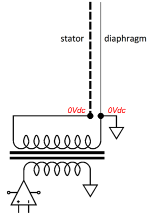
I can envision two ways to drive such an electrostatic speaker.
The approach on the right is to drive the diaphragms, which means that the diaphragms must present a low resistance. The approach on the left drives the stator. In both examples, the two diaphragms move in phase, which means that effectively we have two single-ended diaphragms working in tandem, so the distortion inherent in single-ended operation cancels as it does in a regular push-pull electrostatic loudspeaker. The stator still needs to be perforated, so the diaphragms do not work into a compression chamber. These holes might actually prove useful in damping the diaphragms. In my last post, I mentioned the white paper by the headphone maker, Final. Alas, I cannot find this paper online. The punch line was that planar headphones run into the problem of producing low bass without the diaphragm slapping against the magnet structure. If the diaphragm is stretched extra tight, we lose low frequencies. If we apply some damping goo to the diaphragm, we limit high-frequency reproduction. Final's workaround is to use a diaphragm under moderate tension, so low-frequency extension is possible, but apply a series resistance in the form of air viscosity. In other words, small-hole perforation is used so the air's own fluid viscosity dampens the motion of the diaphragm. Think about the shock absorbers on your car; they introduce a resistance in parallel with the springs, which effectively are capacitive, while the car's mass is effectively inductive; in short, a damped LCR circuit. As I thought this is such a dang good idea that somebody must have patented it. Someone did. US Patent Number 4289936 details a fantastically interesting electrostatic loudspeaker system by John P. Civitello.
No doubt Mr Civitello effort was before its time (1981) and with modern materials and construction techniques, his design could be resurrected.
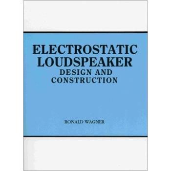
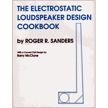
At Least Two Essential Books
The third book that is always referenced, but which I haven't read, is F. V. Hunt's book, Electroacoustics: The Analysis of Transduction, and Its Historical Background, written in 1954, Well, it's happened again: I have much more to say, by not the time to say it. In other words, more to come on this topic. //JRB
User Guides for GlassWare Software Since I am still getting e-mail asking how to buy these GlassWare software programs:
For those of you who still have old computers running Windows XP (32-bit) or any other Windows 32-bit OS, I have setup the download availability of my old old standards: Tube CAD, SE Amp CAD, and Audio Gadgets. The downloads are at the GlassWare-Yahoo store and the price is only $9.95 for each program. http://glass-ware.stores.yahoo.net/adsoffromgla.html So many have asked that I had to do it. WARNING: THESE THREE PROGRAMS WILL NOT RUN UNDER VISTA 64-Bit or WINDOWS 7 & 8 or any other 64-bit OS. One day, I do plan on remaking all of these programs into 64-bit versions, but it will be a huge ordeal, as programming requires vast chunks of noise-free time, something very rare with children running about. Ideally, I would love to come out with versions that run on iPads and Android-OS tablets.
//JRB |
Kit User Guide PDFs
And
High-quality, double-sided, extra thick, 2-oz traces, plated-through holes, dual sets of resistor pads and pads for two coupling capacitors. Stereo and mono, octal and 9-pin printed circuit boards available.
Designed by John Broskie & Made in USA Aikido PCBs for as little as $24 http://glass-ware.stores.yahoo.net/
The Tube CAD Journal's first companion program, TCJ Filter Design lets you design a filter or crossover (passive, OpAmp or tube) without having to check out thick textbooks from the library and without having to breakout the scientific calculator. This program's goal is to provide a quick and easy display not only of the frequency response, but also of the resistor and capacitor values for a passive and active filters and crossovers. TCJ Filter Design is easy to use, but not lightweight, holding over 60 different filter topologies and up to four filter alignments: While the program's main concern is active filters, solid-state and tube, it also does passive filters. In fact, it can be used to calculate passive crossovers for use with speakers by entering 8 ohms as the terminating resistance. Click on the image below to see the full screen capture.
Tube crossovers are a major part of this program; both buffered and un-buffered tube based filters along with mono-polar and bipolar power supply topologies are covered. Available on a CD-ROM and a downloadable version (4 Megabytes). |
||


 These triangular panels were meant to be assembled into an array.
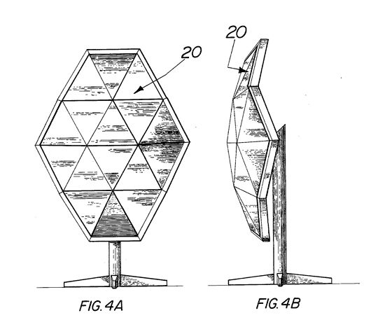


| www.tubecad.com Copyright © 1999-2017 GlassWare All Rights Reserved |