| John Broskie's Guide to Tube Circuit Analysis & Design |
04 December 2016 Post 404
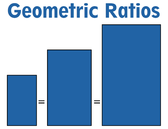
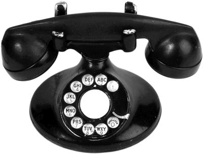
Geometric Crossover Frequencies With sound and loudspeakers, we are far more concerned with octaves rather than individual frequencies, which makes sense, as there are 19,980 whole frequencies that we can hear, assuming an ability to hear from 20z to 20kHz—and an infinite number of non-whole-number frequencies exists between 20Hz and 21Hz, such as 20.1Hz and 20.7892482Hz. Let us try to put things in perspective. Consider a subwoofer that covers frequencies from 30Hz to 120Hz, which equals two octaves, as 30Hz to 60Hz counts as one octave, as does 60Hz to 120Hz. This subwoofer will strain to cover these 90 frequencies, whereas a tweeter will breeze through 10,000Hz and 10,090Hz. In fact, if due to some defect in its manufacture the tweeter experienced a notch in its frequency response, so that it could not reproduce frequencies between 10,000Hz and 10,090Hz, not even a professional audio reviewer would observe their absence. In other words, not all spans of 90 frequencies are equal. In contrast, lose two octaves, say between 1kHz and 4kHz, and everyone will notice. Returning to the example of the subwoofer, if we want a tweeter to work as hard as the subwoofer that covers two octaves, the tweeter should crossover at 5kHz, so it too could cover two octaves, from 5kHz to 10kHz, and from 10kHz to 20kHz. We would say of the sub woofer and tweeter in this example that they held to a geometric proportion in terms of bandwidth. It is also possible that the woofer cost twice as much as the midrange, which in turn cost twice as much as the tweeter; thus, they all would they hold to a geometric proportion in terms of cost. What fails to hold to a geometric proportion is the midrange, at least in terms of frequency response, as it must cover the band of frequencies from 120Hz to 5kHz, far more than two octaves. All that is needed to make things fairer is some simple math. Starting with just two loudspeaker drivers, we will want to find the geometric center frequency between the lowest frequency and the highest frequency reproduced. Our instant assumption is that the speaker's bandwidth extends from 20Hz to 20kHz. Does it really? Few loudspeaker can actually put out 20Hz with any vigor. More importantly, should the bandwidth extend so far in both directions? The human ear likes balance. For example, when you talk on the phone, the bandwidth fiercely constricted. Voices can extend down to 80Hz and go up to 14kHz, but typical phones only cover 300 Hz to 3.4kHz. Yet you have no problem recognizing your beloved's voice or guessing the nationality of the call-center operator. How is that possible considering that the phone system has thrown away most of the seemingly needed bandwidth? The answer is balance. The audio-frequency truncation was carefully chosen to to sound both intelligible and natural. Now if someone were to come out with phone subwoofer that would broaden the phone's bandwidth down to 20Hz, the result would fail to please all but diehard Beats headphone owners, as the resulting sound would seem unnatural, overly thick and indistinct. How can adding more result in less?
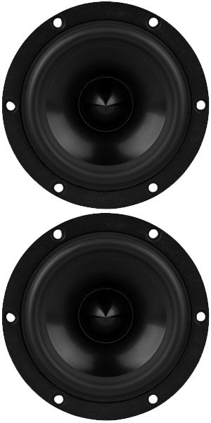
In this example of the ThunderPhone™, the tonal balance was ruined. If we wish to maintain balance, we must also augment the high frequencies, not just the lower frequencies. For example, if we made a phone that went down just one octave lower, from 300Hz down to 150Hz, then we must extend its high frequency response up one octave, 3.4kHz to 6.8kHz. This would result in a balanced sonic presentation. The rule I remember is that the geometric center of the bandwidth should be 1kHz for a balanced tonal presentation. Thus, 300Hz to 3.4kHz works, as does 100Hz to 10k and 50Hz to 20kHz. This geometric center frequency of 1kHz works well with human voices, as they typically extend from 100Hz to 10kHz, so 1kHz is the perfect geometric center frequency. If you listen exclusively to piccolo music, then a much higher geometric center frequency would be needed; listen exclusively to drum music, a much lower frequency. Another example might be a great-sounding mini-monitor loudspeaker that went from 120Hz to 12kHz. After searching through its spec sheet, you might conclude that what this loudspeaker really needed to sing was an added super-tweeter that would go out to 40kHz. Yet, when the super-tweeter is added, the loudspeaker sounds thin and shrill. Conversely, we could have added just a hefty subwoofer to this 120Hz to 12kHz speaker, taking the response down to 15Hz. Once again, the loudspeaker would sound worse, sounding thick, fat, and lugubrious. Balance demands that we add both the subwoofer and super-tweeter. For over four decades now, I have shut off my powered subwoofers late at night or early in the morning, so as not to annoy anyone sleeping. Ideally, I should have been able to impose a low-pass filter on the playing loudspeakers, in order to restore balance, say an 10kHz low-pass filter to match the 100Hz crossover frequency. This might argue for powered super-tweeters, which could be shut off along with the subwoofers. If we are happy enough to forgo both additions, but wish to set the small loudspeaker's crossover at the geometric center of its bandwidth of 120Hz to 12kHz, we only need to grab a hand calculator. We first multiply 120 against 12000, which yields 1,440,000. We then take the square-root of this number, which produces 1,200Hz as the geometric center frequency, as 1200Hz/120Hz = 12000/1200. If your first thought is that 1,200Hz is an awfully low crossover frequency for a dome tweeter, you are right it is. But what if you didn't use a 1inch dome tweeter, but used a 2inch dome midrange instead? Or a small fullrange driver instead? Remember, since the loudspeaker can only go down to 120Hz, we want to purposely truncate its high-frequency response to 12kHz. In fact, I bet that two identical 4inch fullrange drivers might work best of all, as both would share identical frequency response and phase aberrations.
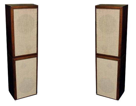
Why not just use one of these drivers instead? While eliminating a crossover is a great advantage, the benefits that accrue from giving each driver half of the workload are greater. Think about it: a single 4inch driver will have to move a relatively big distance to get bass output at 120Hz. This movement must coexist, however, with the micro small high-frequency movements at 12kHz. The result is FMD, frequency modulated distortion, which is a form of Doppler distortion, but differs in that the 12kHz tone is both pushed higher and stretched lower by the diaphragm's big bass movements. But by halving the bandwidth at 1,200Hz, the FMD is substantially reduced. (Notice that the non-geometric center frequency would be 5,940Hz, as (12000 - 120)/2 = 5940, which we certainly do not want, as the high-frequency driver would cover only one octave, while the low-frequency driver would cover nearly six octaves.) A story that I have told dozen of times—because I found the results so dazzling—is from when I was a college student. I had made a small active-passive crossover box that held several OpAmps for the active third-order low-pass filter and a passive, single-capacitor high-pass first-order filter, both of which shared a 100Hz crossover frequency. Everyone who listened to it wanted one. One friend owned a pair of the big Advent loudspeakers and he wanted one and got one from me. When I visited his place, I was surprised to see two pairs of big Advent loudspeakers, not the subwoofer he had been talking about getting. (Apparently, he had seen the other used pair for sale in paper's classifieds section and he couldn't resist buying them.) He had stacked one speaker atop another and had given the bottom loudspeakers their own stereo power amplifier.
I held peevishly low expectations. As I saw it, he had taken a giant leap sideways, as the bass would extend no lower than it had before. I was, however, startled to hear fabulous sound sound emerge from the four identical loudspeakers. Not twice as good, but seemingly four times better. The midrange articulation and bass definition were improved far beyond my expectations, as was the stereo imaging. I marveled at how 1 + 1 could equal 4 or more. Later, I read a magazine article on FMD (possibly Audio magazine, but also possibly the JAES), and things began to make more sense. With each halving of frequency, a driver's diaphragm must double its excursions to maintain equal SPL. For example, a nominally 12-inch diameter might hold a diaphragm of 10.5 inches in diameter. This diaphragm would have to experience excursions of 1mm to achieve an SPL of 100dB at 100Hz; to do the same at 50Hz, however, requires excursions of 4mm; and at 25Hz, excursions of 16mm. See www.baudline.com/ for an online calculator. Of course, the use of two stereo power amplifiers helped a great deal, as the high-frequency amplifier might not have clipped as readily as before.
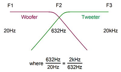
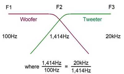
What if the two fullrange drivers could, miraculously enough, extend from 20Hz to 20kHz? The geometric center frequency would equal the square-root of (20 x 20k), or 632Hz. Far more likely, the fullrange would only cover 100Hz to 18kHz. In this case, assuming a subwoofer was used below 100Hz, the geometric center frequency would be 1,342Hz.
With computer loudspeaker system that held a common subwoofer that crosses over at 250Hz, the geometric center frequency would be 2,120Hz. This assumed that the fullrange drivers topped off at 18Khz, if they extended out to 22kHz, then the geometric center frequency would be 2,345Hz; and if they fell off at 15kHz, 1,936Hz.
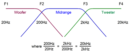
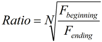
What about three-way systems? Now it is time for a generalized formula that would cover loudspeaker systems from two-way to six-way or N-way arrangements, where N might ten or twenty. What we seek is the geometric ratio that we would multiply against the lowest frequency and then again against this resulting frequency and on and on until we run into the final frequency limit. Beginning and ending frequencies set the frequency bandwidth limits and N is the number drivers. Thus, with a three-way systems, N would equal 3. If the beginning frequency is 20Hz and the ending frequency is 20kHz, the ratio with a three-way system would be 10, as ten is the cube-root of 20k/20 (or 1,000). So, we would multiply 20Hz by 10 and get crossover frequency between woofer and midrange, 200Hz. Then we multiply 200Hz by 10 and get 2kHz as the crossover between the midrange and tweeter. The result is that each driver covers the same number of octaves; in this example, each covers one decade of frequencies. On the other hand, if our three-way loudspeaker is going to be used with a subwoofer that crosses over at 100Hz, then we must find the geometric ratio for a beginning frequency of 100Hz and an ending frequency of 20kHz.
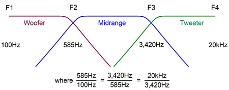
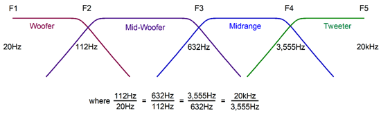
What about four-way systems? We want to find the three numbers (F2, F3, & F4) that fall in between the lowest frequency (F1) and the highest frequency (F5).
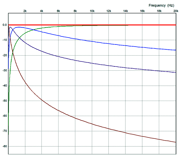
Now, we have a choice, as we could use our generalized formula or we could treat the four-way system as comprising two two-way systems. If we choose the second approach, we would first find the center-most crossover frequency (F3) by taking the square-root of the sum of F1 against F5. once we have this frequency (F3), we take the square-root of the product of it against the lowest frequency (F1) which will give us the crossover frequency between the woofer and mid-woofer. All that is left is to find the crossover frequency between the midrange and tweeter, which we find by taking the square-root of F3 x F5, giving us F4. With five-way and above systems we are better off sticking to the formula. Here is a thought experiment: how many drivers would be needed in a loudspeaker system that used one driver per octave, starting at 20Hz? What if we started at 80Hz instead? Here is a small test: you have seen all the data in the following graph before in my last post. Do you recognize it?
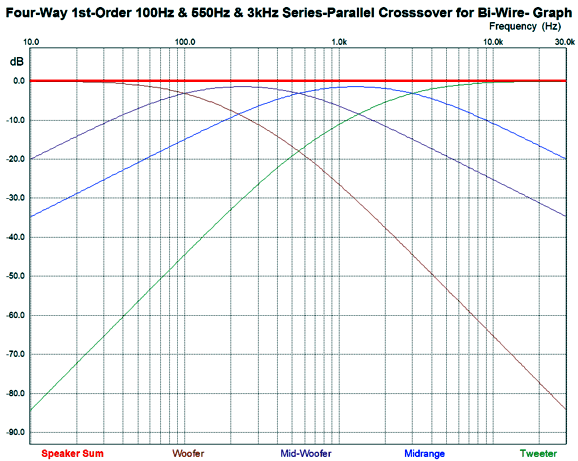
The reason you don't is that the graph is linearly scaled on its X-axis, not logarithmically. The brown trace belongs to a woofer that covers 20Hz to 100Hz, yet barely shows up in this graph, yet its musical contribution is huge. By switching to X-axis to a log scale, it shows up boldly.
With the log scaling, we can clearly see the mid-woofer and midrange are geometrically equal.
Special Thanks to the Special 61 (Stuck on 61)
If you have been reading my posts, you know that my lifetime goal is reaching post number one thousand. I have 596 more to go. My second goal is to gather 1,000 patrons. I have 939 patrons to go. If you enjoyed reading this post from me for the last 18 years, then you might consider becoming one of my patrons at Patreon.com. It would make a big difference to me. Thanks.
Direct-Drive Electrostatic Power Amplifiers
The problem with the step-up transformer is the same problem with a tube amplifier's step-down transformer: good ones are hard to make, to find, and to pay for. In addition, as a good general rule, the closer to a unity-winding ratio, the better the audio transformer. In theory, we can wind any ratio we want, say one-to-ten-thousand—it's just wire wrapped around a metal core after all. In practice, you seldom find ratios above one-to-thirty. In fact, I remember seeing a Quad schematic showed two step-up transformers per speaker, which effectively doubled the winding ratio, so that two 1:30 transformer can effectively become one 1:60 transformer.
The first time that I heard direct-drive I was hooked for life. Long, long ago, I owned Audio Technica ATH-70 electret headphones, which sounded fabulous, as long as you didn't compare them to Stax electrostatic headphones. These were electrostatic-like headphones that held a pre-polarized diaphragm, so no plugging into the wall socket was needed, as no high-voltage-bias voltage was needed. An audio step-up transformer, however, was required. Ready for this: I bought a 200W solid-state power amplifier just to drive these headphones and used my 20W power amplifiers to drive my loudspeakers. Of course, everyone who saw the setup thought the reverse was the case. Even with the big power amplifier, the headphones lacked sparkle and dynamics. Then one day, I dug out my Dynaco ST-70 power amplifier and tried an insanely dangerous test. DON'T DO THIS! I attached the headphones' stators directly to the output tubes' plates and disconnected the loudspeakers. The sound, although somewhat tarnished by power-supply noise, sounded vastly more transparent and dynamic. That started me down the path of building direct-drive electrostatic headphone amplifiers. Eventually, I broke down and bought a pair of Stax electrostatic headphones, which nearly broke my bank account balance. The conclusion I came to was that if at all possible go the direct-drive approach and forget about output transformers.
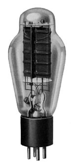
Of course, this is where tubes enter the story, as tubes live and breathe high-voltages. Well, up to a point they do. Most audio tubes, such as the 12AX7 and 12AU7, have stated plate voltage limits of 250V, just enough for electrostatic headphones, but not enough for big panels. Even output tubes, such as the EL34, KT88, and 300B are relatively voltage-limited. To get true high-voltage limits, we need to look to transmitting tubes, such as the 211 and 845. And even theses will not be happy with a 4kV plate-voltage swings and bigger transmitting tubes will be needed. One possible workaround is to use normal audio tube power tubes, such as the 6550 and KT88, with a moderate step-up transformer, say one that offers a step-up ratio of 1:4, not 1:30. Where could we find such an output transformer? Easy. It's called a normal tube-audio output transformer with ultra-linear taps. For example, the Dynaco ST-70 output transformer, the A-470, offers a UL tap at 33%, which would result in a 1:3 step-up ratio.
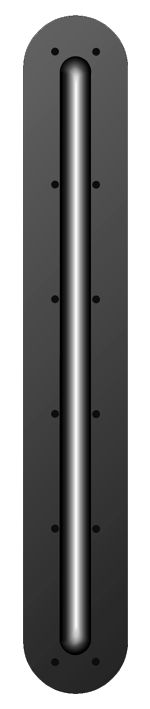
Notice that we using the transformer's primary as an autoformer and that we leave the secondary floating. Of course, we could put the secondary to use. For example, it could provide negative feedback to the input or driver stages; or, it could drive a woofer. If you have been reading my posts on the electrostatic loudspeaker topic, you will have gleaned that I believe that we might have got it all wrong, that the electrostatic is not ideally suited to being a tweeter or full-range driver due to it being a capacitor, that perhaps we would be better off by limiting its use to the lows and midrange and letting a dynamic loudspeaker driver handle the highs, such as a ribbon or dome tweeter design. Heresy, yes I know, but the math backs me up. At 20Hz, a 10nF (0.01µF) capacitor presents 796kohm impedance, but at 200Hz, 79.6kohm; at 2kHz, 7.96kohm; and at 20kHz, 796 ohms. It is a thousand times easier to drive a 796kohm load than a 796-ohm load. If we limit the high-frequency response to 4kHz, however, the load is 4kohm, which is just about perfect for many output tubes. One thought I have long held is that someone should make an elongated dome tweeter. Imagine a 1inch dome tweeter sliced in half and then then stretched up vertically.
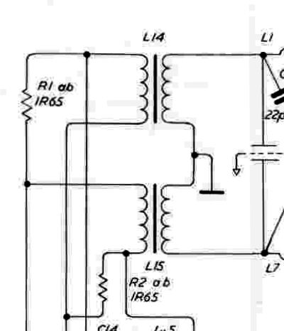
Instead of a round dome and voice-coil we would have a long oval dome and voice-coil. Why? It would make a fine line source and because of the much greater surface area, it could go much lower, say from a presently comfortable 4kHz down to 600Hz, which would have been unthinkable with a 1inch dome. Of course, rather than use up a good tube-output transformer, we could have a custom-made autoformer built to our specifications. I showed the following schematic before, which uses an autoformer.
Note the grounding of the center-tap and the negative power-supply rail. Although we could wind any step-up ratio we desire, we face the current limit imposed by the output tubes. For example, say each output tube idles at 75mA and that step-up ratio is 1:4. 600V plate-to-plate voltage swings become 2400V stator-to-stator voltage swings. The only problem is that we can get anything for free, so while we increased the voltage swings by fourfold, we also decreased the potential current swings by fourfold, leaving us with a peak current swing of 0.175A/4 or 37.5mA. This might appear to be a lot of current—and it is at 20Hz—but at 20kHz, working into a 10nF load capacitance, it's paltry. Remember that slewrate equals Slewrate = (2 × pi × Freq × Vpk) / 1,000,000 where the slewrate is in V/µS. And that current equals slewrate against capacitance. I = Slewrate x Capacitance where slewrate is in V/µS and the capacitance is in µF. Do the math and you see that the 10nF load capacitance requires a current peak swing of 3A at 2400Vpk at 20kHz, which would equal 3600W into a resistive load. Of course, I will be the first to point out that we do need full-power bandwidth out to 20kHz, as 6kHz to 8kHz is sufficient. But this only reduces the peak current swing to 1A. The obvious workaround is to either make a smaller electrostatic panel with far lower capacitance or use many output tubes in parallel or reduce the high-frequency cutoff—or all of the above. Another workaround would be to use power MOSFETs instead of output tubes. MOSFETs can deliver current, lots of it, as in 10 to 600 amperes, such as the IXTK600N04T2.
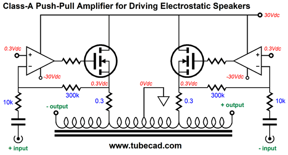
With a winding step-up ratio of 1:50, the two power MOSFETs could deferentially swing 48Vpk, which would result in 2400Vpk stator-to-stator swings. This amplifier requires a balanced input signal and each MOSFET-OpAmp combination offers a gain of 30. The 10k input impedance might prove too low for some tube line stages, however, so the following variation can be used.
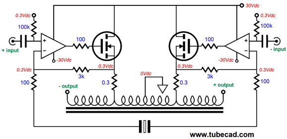
The input impedance is now 100k. Note the odd-looking capacitor at the bottom of the schematic; it's my symbol for a non-polarized electrolytic capacitor. A big capacitor value is required due to the two 100-ohm feedback resistors. If we wish to use an unbalanced input signal, the following variation will do the job.
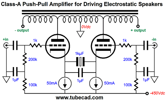
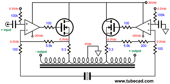
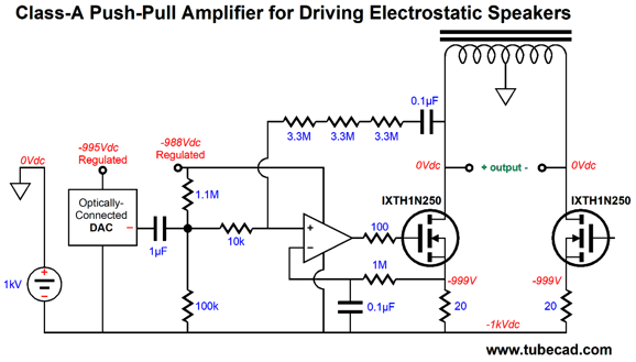
Note the added 200-ohm feedback resistor on the right side, in series with the 5.9k resistor. It is needed to balance the gain on both sides, as the left half runs as a non-inverting amplifier with a gain equal to (5.9k + 200)/200 or 30.5; in contrast, the right half runs as an inverting amplifier with a gain equal to (5.9k + 200)/200 or 30.5. In other words, with out this added resistor, the the right half's gain would equal to 5.9k/200 or 29.5. So far, we haven't seen any direct-drive amplifiers, although the autoformer is somewhere in the middle of direct-drive and transformer coupled. In fact, we can use inductive devices within a direct-drive electrostatic amplifier, as shown below.
Only the complete left of the schematic is shown, but the right half simply mirrors the left half. The center-tapped inductor allows us to drive the electrostatic panel with close to 2kv of stator-to-stator voltage swings. Each power MOSFET dissipates 50W at idle, which is crazy hot, so huge, massive heatsinks would be required. Do not forget that this is a class-A amplifier—for real. Note how an optically connected voltage-out DAC is used, which allows us to get away with locating it down at -1,000Vdc. The OpAmp's output gets inverted by the MOSFET, so we must flip its two inputs, so the non-inverting input effectively becomes the inverting input. The OpAmp drives the MOSFET and sets the MOSFET's idle current through the RC filter at the source resistor, which filters away the AC signal. A negative feedback loop (the three 3.3M resistors) returns the output to the OpAmp, which lowers the distortion and output impedance. On the other hand, if we drive the MOSFET's source, rather than its gate, we do not need to flip the OpAmp inputs, as the following schematic shows.
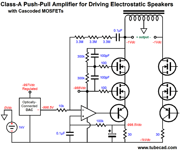
(Yes, I sneakily added lots of stuff. Baby steps, baby steps, as the late Gizmo used to remind me over and over again.) The PNP transistor actually drive the MOSFET's source, but it gets its marching orders from the OpAmp. The cascoded MOSFETs allow us to either use a higher negative power supply or retain this rail voltage and use cheaper, lower-voltage MOSFETs. In addition, the cascoded MOSFETs halve the dissipation for each MOSFET. Note that the DAC's output is now DC coupled to the 10k gain-setting resistor. The 100pF capacitors help overcome the MOSFET's high input capacitance. The only thing that I can see complaining about is the negative power-supply rail. Why? Many tube lovers just hate negative power supplies. Why? Well, for one they falsely imagine that they cannot use a tube rectifier; you can. As they see it is unfortunate that a B+ is need, but it is tragic, if not unforgivable, that a negative power-supply rail might be required. Actually, the optical-coupling is a bit of a pain, as nothing beats keeping things at ground potential. We could stand everything on its head—well, almost everything, as the following schematic shows.
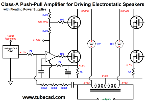
The DAC and OpAmp now reside at ground potential as does the center-tapped choke. The price we paid was having to use two floating high-voltage power supplies per channel. Yes, four for a stereo amplifier. Floating means not grounded and, thus, able to move up and down freely. The two amplifier outputs being at -1Vdc at idle is the result of the MOSFET idle current against the inductor's DCR. How does this amplifier work? As one side's MOSFETs increase their current conduction, they pull down the top MOSFET's drain voltage, which in turn forces that side's output down. At the same time, the other side's MOSFETs are conducting less, so the unstressed inductance forces this side's output up. The electrostatic panel sees the voltage difference across its stators. Okay, I want you to fasten your mental safety-belt now, as we are about to go on a wild ride. What if we could lose the many floating HV power supplies and replace them with just one high-voltage power supply, even in a stereo amplifier? One high-voltage power supply to power them all! We can; we just need an additional center-tapped inductor. (In fact, the two winding could share a single core.)
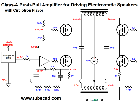
The top center-tapped inductor and added 10µF capacitors decouple the MOSFETs from the single power supply. (Effectively we have made floating power supplies out of the 10µF capacitors.) Since "ground falls mid load, this amplifier has a distinct Circlotron flavor. Why are the two outputs now at 0Vdc, not -1Vdc? The bottom center-tapped inductor doesn't experience any net DC current flow, seeing only AC voltage swings. Well, I have run out of time again; and, once again, I am nowhere near being done. Next time. By the way, if the Mac Arthur Foundation ever calls you, asking if you know of anyone deserving of one of their fellowship grants, please send them the above schematic ;)
//JRB
User Guides for GlassWare Software Since I am still getting e-mail asking how to buy these GlassWare software programs:
For those of you who still have old computers running Windows XP (32-bit) or any other Windows 32-bit OS, I have setup the download availability of my old old standards: Tube CAD, SE Amp CAD, and Audio Gadgets. The downloads are at the GlassWare-Yahoo store and the price is only $9.95 for each program. http://glass-ware.stores.yahoo.net/adsoffromgla.html So many have asked that I had to do it. WARNING: THESE THREE PROGRAMS WILL NOT RUN UNDER VISTA 64-Bit or WINDOWS 7 & 8 or any other 64-bit OS. One day, I do plan on remaking all of these programs into 64-bit versions, but it will be a huge ordeal, as programming requires vast chunks of noise-free time, something very rare with children running about. Ideally, I would love to come out with versions that run on iPads and Android-OS tablets.
//JRB |
Kit User Guide PDFs
And
High-quality, double-sided, extra thick, 2-oz traces, plated-through holes, dual sets of resistor pads and pads for two coupling capacitors. Stereo and mono, octal and 9-pin printed circuit boards available.
Designed by John Broskie & Made in USA Aikido PCBs for as little as $24 http://glass-ware.stores.yahoo.net/
The Tube CAD Journal's first companion program, TCJ Filter Design lets you design a filter or crossover (passive, OpAmp or tube) without having to check out thick textbooks from the library and without having to breakout the scientific calculator. This program's goal is to provide a quick and easy display not only of the frequency response, but also of the resistor and capacitor values for a passive and active filters and crossovers. TCJ Filter Design is easy to use, but not lightweight, holding over 60 different filter topologies and up to four filter alignments: While the program's main concern is active filters, solid-state and tube, it also does passive filters. In fact, it can be used to calculate passive crossovers for use with speakers by entering 8 ohms as the terminating resistance. Click on the image below to see the full screen capture.
Tube crossovers are a major part of this program; both buffered and un-buffered tube based filters along with mono-polar and bipolar power supply topologies are covered. Available on a CD-ROM and a downloadable version (4 Megabytes). |
||


| www.tubecad.com Copyright © 1999-2017 GlassWare All Rights Reserved |