| John Broskie's Guide to Tube Circuit Analysis & Design |
|
02 February 2018 Post 411
Aikido Hybrid Amplifiers
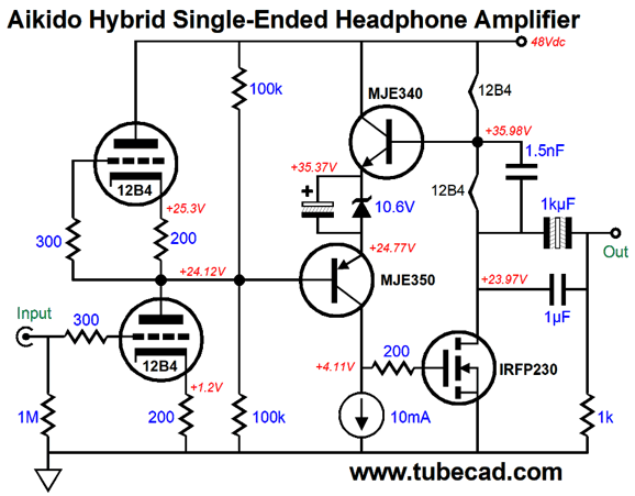
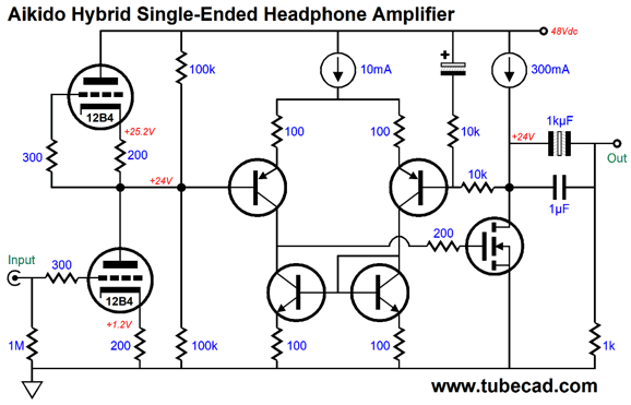
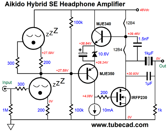
The input stage holds two 12B4 triodes in a totem-pole arrangement, which defines a grounded-cathode amplifier with an active plate load. Because these two triodes share the same cathode resistor value, they will split the B+ voltage in half between them (assuming fairly well-matched triodes). Moreover, they will split the power-supply noise and provide a signal gain equal to half of the triode's amplification factor (mu). The gain must equal half of the triode's mu in this symmetrical setup. The formula for the gain from a grounded-cathode amplifier with an unbypassed cathode resistor is: Gain = muRa/(Ra + rp + [mu +1]Rk) If we replace Ra, the plate resistor, with rp + (mu + 1)Rk and then simplify, we end up with Gain = mu/2 The amplifier's output stage holds a bastode differential amplifier (the PNP and NPN transistors) that drives and controls the N-channel MOSFET's current conduction. The two tube heater elements define a two-resistor voltage divider that functions as the output stage's negative feedback loop. Unlike most negative feedback loops, this one terminates into the B+ voltage, not ground. Why? We purposely want to the power-supply noise to appear at the feedback string's end, so that it can null at the output stage's output.
Now it is baby-steps time. Don't I have it backwards here? Shouldn't I have started with baby-steps and ended with the above? Perhaps. Whenever I read a technical article (or any supposedly rigorous article), however, I begin with the summery; I then note the subsection titles and illustrations; finally, I start reading the first paragraph. This procedure may seem a waste of time, but I prefer having a quick overview of the jungle, knowing if cannibals lurk within and what the deadly snakes look like, before I enter it with a machete. Of course, many readers only need to see the schematic. For a few, that is all they understand, as they cannot read English. I know they exist, as I get email from them, email translated into English by Google Translate, which always leaves tell-tale clues. (I remember some translation software turning a "Burr-Brown DAC" into a "chilled-chestnut" DAC.) The other clue that gives away their inability to read English is that their email will ask the questions that my post answered in detail. When I examine or design an amplifier, I always begin at the end, i.e. the output stage. In this little OTL headphone amplifier, the output stage is simple enough. A TO-247 power MOSFET works into a resistor load at its drain, making this output stage a class-A, single-ended design by necessity. The twist here is that two resistors are actually two tube heater elements in series.
We find the heater element's resistance by dividing the heater voltage by the heater current draw; in the case of the 12B4, we get 12.6V divided by 300mA, which yields 42 ohms as the result. So, the MOSFET is loaded by 84 ohms. On the other hand, we could give the heaters their own separate power supply.
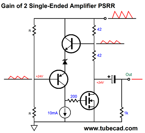
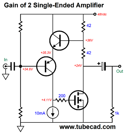
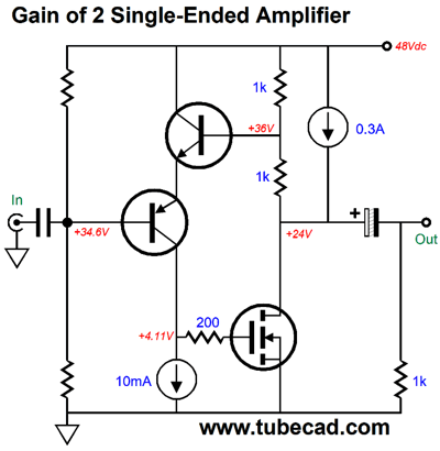
But in both cases, the NPN transistor needs to attach to a negative-feedback loop. In fact, we could use the two 1k resistors and the heater elements at the same time. But as a headphone amplifier does not need to swing more than a few volts of output, so we might as well do something useful with the excessive voltage and current draw. The two transistors define a differential bastode stage. We could use a more conventional differential stage, such as the following.
Once again, the same gain of 2 is realized by the solid-state portion of the circuit and the output MOSFET still runs in single-ended class-A. The key feature these two topologies share is that the negative feedback loop terminates into the B+ voltage, not ground.
Heater Madness
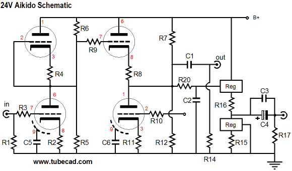
About ten years ago, I sold a 24V Aikido kit, which was supposed to use four 6GM8/ECC86/6N27P tubes. Even ten years ago, these tube were becoming obscenely rare, so many used for 6DJ8/E88CC/6922 tubes instead. Several wrote to me, proclaiming the great sound they were getting. I replaced my precious NOS 6GM8s with four 6DJ8 tubes. Drastic reduction in sound quality. The sound took on a splashy character that displeased me greatly. I tried a bunch of different 6DJ8s, including some supremely expensive NOS types, such as the Dutch cinch-waist E88CC tubes. No 6DJ8 sounded better than the 6GM8s I had been using. Thus, I implored those who had written me to try the 6GM8s instead. The answer I always got back was that they liked the sound they were getting with the wrong tubes far more than what they were hearing before that this upgrade in tube types was not urgent. I then pretty much gave up. A few years ago, I made some experiments with super-low B+ voltages and the 6DJ8. Instantly, I heard the same splashy sound. I was about to give up a second time, when I recalled hearing a similar sound from a different tube being run under low plate voltages; moreover, I remembered my workaround. Thus, I drastically reduced the heater voltage on the 6DJ8s. The splash was gone. How is this possible? Long ago, I remember reading a fascinating electronics journal article (perhaps the Proceedings of the IRE), wherein the author had just performed an exhaustive distortion analysis of several new pentodes. He had a clear ranking from best to worst. Before submitting his results, he decided to quickly run the distortion tests again. Bad news. His results did not repeat the same ranking as the time before had. He was at a loss to explain the new conflicting results. He poured over his extensive lab notes. (Good man.) Only one variable was different: the heater voltage. He had used a regulated power supply for the B+ voltage, but the heaters just got an AC winding and the wall voltage had risen the day of the second test (perhaps it was Saturday morning and the big power consumers were taking the day off or still asleep). He then lowered the AC heater voltage to the previous day's level. Once again, his original ranking were confirmed. The higher heater voltage had provoked greater distortion in the lowest-distortion pentode. He then went further and lowered the heater voltage below the previous day's level: even lower distortion resulted. Eventually, he found that a heater voltage so low that the distortion began to climb, rather than fall.
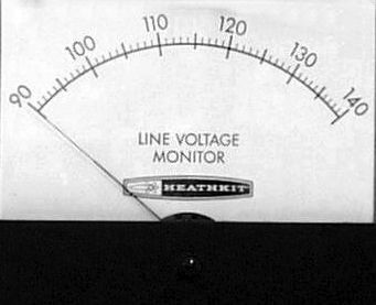
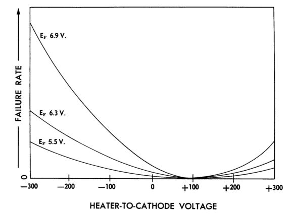
This article has haunted me for decades. Why? Many are running old tube power amplifiers and preamps that were built when the nominal wall voltage was 112Vac or 115Vac, but being used with today's much hotter wall voltages, which can go over 123Vac in some places the USA. Let's do the math. Divide 122Vac by 115Vac and you get 1.06, which against 6.3V equals about 6.7V, far too high. I always check the heater voltage on old gear being used today and, when it is too high, I have placed either thermistors or plain power resistors in series with the heater elements to drop the voltage down to the 6.3V. I do not, however, know of anyone else doing this. Of course, if you are running regulated DC on your heaters, you need not worry. I also know of a company that made tube-based professional audio equipment that used 5V voltage regulators for their heater power supplies. At the time, I was horrified to hear this, but the owner told me that the tubes seldom age or fail, with some of their gear being over ten years old and used daily from 9am to 5pm. The graph below is from Robert "Bud" Tomer’s excellent book, Getting the Most out of Vacuum Tubes. Here we see three plots for three different heater voltages, 5.5V, 6.3V, and 6.9V against the heater-to-cathode voltage. The interesting thing to note is that 0-volts Vgk does not yield the lowest failure rate. In fact, referencing the heater power supply to +80Vdc to +90V appears to result in the greatest reliability.
(I have to admit that I have seen a conflicting graph that show the longest life expectancy with 6.3V, with decreased life with lower or higher voltages. I just don't believe that lower heater voltages could shorten life span. Here is an extreme example: a NOS 6SN7 has sit unused in its box for the last 50 years. Its heater has experienced the lowest possible heater voltage, i.e. 0V, yet the tube functions perfectly.) I tried running an Aikido gain stage with a B+ voltage of only 24V and four JJ 6DJ8 tubes—but with a purposely lower heater voltage. At first, I was timid and I reduced the heater voltage from 6Vdc to 5.7Vdc. My ears liked the result. I grew bold; I went down to 5.1V, then 5V… I stopped at 4.4Vdc. No splash whatsoever, but I dared not go any lower. Okay, what is going on here. With a cathode-to-plate voltage of only 12Vdc, not much current can flow. Indeed, only a trivial amount of current flows, 0.4mA. Such a wimpy amount of current cannot drive low-impedance loads or drive long interconnects laden with capacitance. But in my application, I only needed gain. If the 6DJ8 were running 6.3V on its heater, up to 20mA of current could flow. In the absence of the need to pour heavy current, the normally-hot cathode probably causes more problems than it solves. I have heard that 300B tubes are also sensitive to excessive heater voltages. On the other hand, if heavy current is needed, say to drive long capacitance-laden cables or low-impedance headphones, then the only solution is to use the full heater voltage and a substantial B+ voltage. But if our only goal is to generate only signal gain, then we can get away with both lower heater and B+ voltages. Returning to the Aikido Hybrid design, what happens at start-up, when the heaters are still cold and not conducting?
The two 100k safety resistors come to the rescue and bias up the PNP transistor sufficiently to drop enough voltage across the heater elements. As the triodes warm up, they conduct, and all is well.
Magic Mu
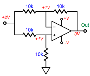
In the above schematic, we see that both inputs see an equal 2V DC offset. The differential amplifier, however, treats these two DC offsets as a common-mode signal and ignores them, presenting no DC offset at its output. As long as any power-supply noise is equally leaking out of both outputs, the differential amplifier will ignore the noise as well. Now, lets look at the Aikido hybrid circuit, but with a power OpAmp.
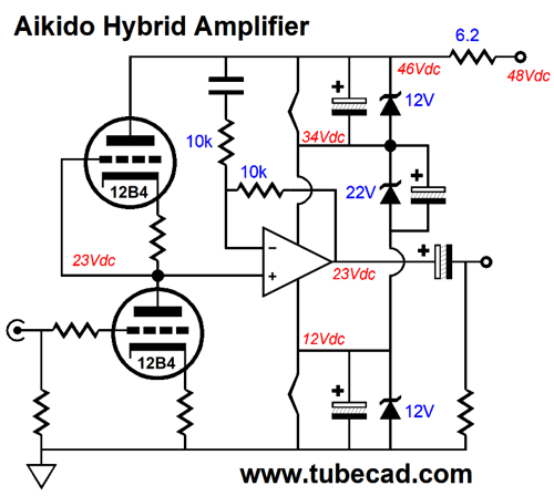
(Here is a quick summery of the above circuit. Once again, we are getting a free heater power supply of sorts. The two 12V zeners limit the maximum voltage across each heater element to 12V and the 22V zener sets 22V as the differential voltage limit for the OpAmp. The 6.2-ohm resistor defines an RC filter with all the capacitors shunting the zener diodes. Note that 48V goes in, but only 46V develops as the B+ voltage, which means that all three zeners can never be engaged at once. The zener that will become the hottest is the 22V one, as it must pass close to 300mA of current, which against 22V equals close to 6.6W of heat.) Once again, as the two identical triodes share the same amplification factor (mu) and plate resistance (rp), and cathode resistor value, they will split the B+ voltage in half between them, and they will split the power-supply noise at the output between the two, just as two equal-valued resistors in series would, for effectively that is what the two triodes are. So, let's replace the two triodes and their cathode resistors with two equal-valued resistors.
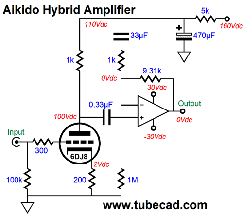
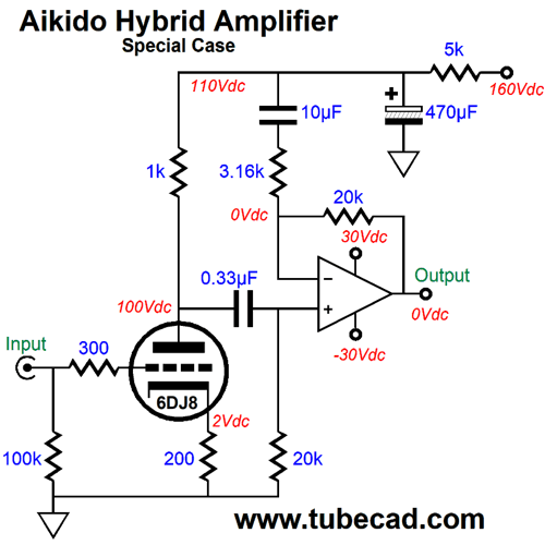
The solid-state output stage is actually a complete amplifier that offers a gain of 2, or +6dB. Combine the two-resistor voltage divider with the amplifier and we end up with a differential amplifier whose input signal is the power-supply noise. Since this signal is common to both the two-resistor voltage divider and the amplifier's negative feedback loop, the differential amplifier ignores the power-supply noise. If the two triodes are not well matched or if the amplifier's feedback resistors are not well matched, the deal is off, as some power-supply noise will leak out the amplifier's output. Well, if we suffer from mismatched triodes, could we purposely mismatch the amplifier's negative feedback resistors? Indeed, we could. What if we only used one triode in a grounded-cathode amplifier configuration? We could and we could find the optimal amplifier negative feedback resistor ratio to ensure a great PSRR. Could we, then, possibly get a much lower or higher gain? No. This is the interesting part: we always end up with a gain equal to the mu of the triode used. Always? Always. Here is an example that uses a 6DJ8 triode.
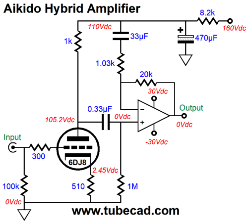
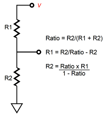
Note both the low 110Vdc B+ voltage and the low 1k plate resistor value. You wouldn't expect to get much gain with such a low value plate resistor and we don’t, as a gain of only 1.47 is realized. In addition, since the plate resistor value is so woefully small in value, this grounded-cathode amplifier exhibits a truly poor PSRR, as 95.1% of the power-supply ripple leaks out of its output at its plate. This 95.1% is what the solid-state amplifier's non-inverting input sees, so its inverting input must see the exact same 95.1% of the power-supply noise to ignore the noise. In other words, we must attach a two-resistor voltage divider from the B+ voltage to the amplifier's output that delivers 95.1% of the AC power-supply noise to the amplifier's inverting input. The formula for a two-resistor voltage divider is simple enough, given R1 & R2 and a desired voltage ratio.
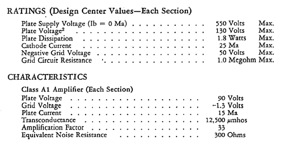
If we set R2 to 20k, then we find that R1 must equal 1.03k, as 20k/0.951 - 20k = 1.03k. A non-inverting, negative feedback-based amplifier's gain is equal to (R1 + R2)/R1; thus, the amplifier's gain is equal to (1.03k + 20k)/1.03k, or 20.417. This amount of gain against the grounded-cathode amplifier's gain of 1.47 equals 30, which just happens to be the 6DJ8's amplification factor. Wait a minute, John; it's amplification factor is 33, not 30; just check the tube manual.
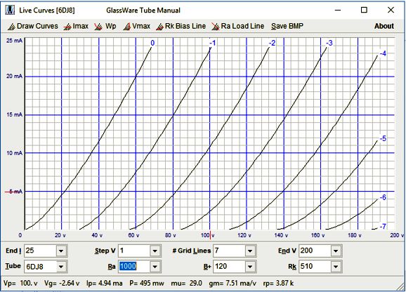
Well, it is and it isn't. Remember that other than its weight and height and diameter, none of a triode's specifications (electrical specifications) are constant. In my SPICE simulations, the 6DJ8 SPICE model specifies a mu of 30 at this plate voltage and this plate current. My own True-Curves triode math model predicts a mu of 29 for the 6DJ8 at 100V of plate voltage and 5mA of plate current.
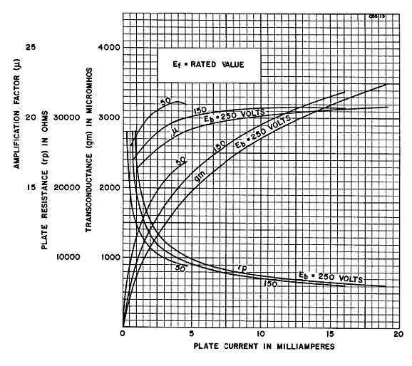
Here is a graph that shows the famous 6SN7's electrical characteristics.
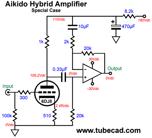
Note that gm, mu, and rp all vary. The mu varies the least, but it still varies. Who knows what current production 6DJ8s actually produce. The interesting thing is that the configuration of part values that results in a power-supply noise null at the output is also the configuration that delivers a final gain equal to the mu of the triode used. Here is another example.
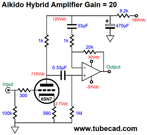
How does this example differ from the previous version? Note the 200-ohm cathode resistor and the doubled idle current. This 6DJ8-based grounded-cathode amplifier stage delivers more signal gain than the previous version, so less gain is needed from the OpAmp, about half as much. Both examples yield the same total gain, which equals the 6DJ8's mu. Here is a 6SN7 based example.
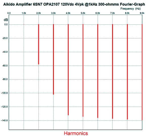
This Aikido Hybrid amplifier delivers a gain of 20. It also offers stellar PSRR. Now, let's mess with the triode's part values.
Here is the SPICE generated Fourier graph for 4V peak into 300-ohms at 1kHz.
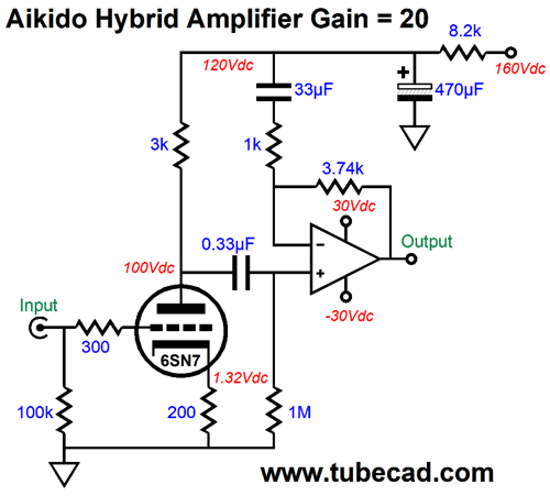
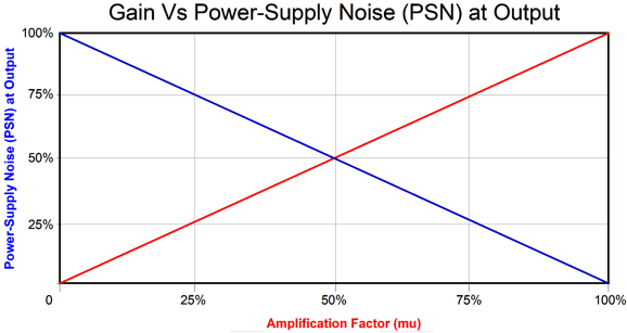
What's not to like here? Different valued cathode and plate resistors, but the same final gain of 20. If we either decrease or increase the gain from the OpAmp, we worsen the PSRR. Why does the magic mu result obtain? It makes sense, if you think about it deeply. The grounded-cathode amplifier's (with an unbypassed cathode resistor) gain stands in inverse proportion to its ability to reject the power-supply noise (PSN). Here is a graph to make the point.
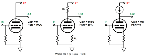
At the extreme left, we get no gain and 100% of the power-supply noise leaks into the output. At the extreme right, we get the full mu of gain and no power-supply noise leakage. Here are the circuit equivalents.
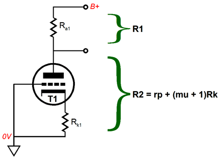
The middle circuit is the equivalent to the totem-pole arrangement with two triodes, each using the same cathode resistor value. What about those cases where the gain is either lower or higher than mu/2? The solution is to realize that the plate resistor and the triode with its unbypassed cathode resistor define a two-resistance voltage divider.
And this circuit's gain is equal to: Gain = muR1/(R1 + R2), or what is the equivalent, Gain = muRa/(Ra + rp + [mu + 1]Rk) In contrast, the formula for AC voltage division is Ratio = R2/(R1 + R2) In other words, they stand in an inverse relation to each other, which explains why the two plotlines in the above graph slope in different directions. Okay, but there is one wrinkle: the resistor on the other side of the coupling capacitor. In all the previous examples, the value was 1M, which is high enough not to cause problems. Unfortunately, many chip amplifiers hold transistor-based input stages that draw current from their two inputs, which will cause a DC offset at the output with a 1M resistor. Ideally, we want to see matched resistance between the feedback and input resistors. In the example below, that matched value is 20k
The 20k resistor is low enough in value, however, to throw off the PSRR and gain calculations. Moreover, it breaks the Magic Mu rule. For example, the gain of the above Aikido Hybrid is not 30, but 20.9. Here is another example:
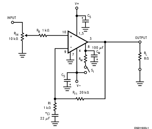
This time, the total gain is just 15.5. By the way, the reason I have sought to use a 20k feedback resistor and a gain of at least ten from the chip amplifier as I created these circuits is that I have held in mind the famous LM3886. This is a rugged and fine-sounding power amplifier, but it is nowhere near being unity-gain stable
Here is the design example offered in its data-sheet .
Note the 20k feedback resistor. Always read the data-sheet thoroughly. The LM3886's data-sheet points out that,
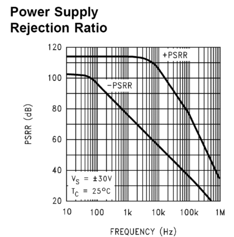
Indeed, it can. I would never let its gain drop below 10 and I would certainly use the full array of Zobel networks on the output. (If I were in a whimsical mood, I might even place a 1-ohm resistor in series with the output, so the hybrid amplifier's Zo would more closely approximate a tube amplifier's Zo. The tube input stage already lends a strong 2nd harmonic signature.) In contrast, many of the Burr-Brown (Texas Instruments) chip power amplifiers are unity-gain stable and most hold FET input stages, such as the OPA549, but they cost twice as much. The OPA549's positive power-supply pin, however, offers a weak PSRR, whereas the LM3886 offers a stellar positive power-supply pin PSRR, as revealed in the graph below.
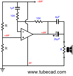
The poorer negative positive power-supply pin PSRR is not a problem with a monopolar power supply, as the negative pin attaches to ground, i.e. the signal reference. Another advantage to the LM3886 is that it can withstand up to 94V of power-supply differential. Say that we limit ourselves to a monopolar power supply of 80V, this would allow the tube much more plate voltage to play with; remember, we are purposely using a low-valued plate resistor. With the 80V power supply, we could get about 80W into an 8-ohm load. Not bad. With a 48V power supply voltage, we could get about 25W, which is far more than any tube-based single-ended power amplifier offers. The following is from the LM3886 data-sheet.
The 2N3904 NPN transistor is there to feed pin 7 a low-impedance, half the B+ voltage; a faux ground in other words. In the Aikido Hybrid, capacitor C1 would terminate into the B+, not ground. An interesting question is, Which tube to use? The 6SN7 comes immediately to mind, but the same triode can be found in the 6J5 and 12J5. Another possibility would be to use a 2A3 or 6B4 or a triode-connected EL84. I love the idea of a unicorn like monobloc amplifier with one tube protruding up through the top of its chassis. Or, how about a single tube mounted horizontally, which protrudes through the front faceplate? We can call it the "Monocle Amplifier." How's this for a logo?
//JRB
User Guides for GlassWare Software
For those of you who still have old computers running Windows XP (32-bit) or any other Windows 32-bit OS, I have setup the download availability of my old old standards: Tube CAD, SE Amp CAD, and Audio Gadgets. The downloads are at the GlassWare-Yahoo store and the price is only $9.95 for each program. http://glass-ware.stores.yahoo.net/adsoffromgla.html So many have asked that I had to do it. WARNING: THESE THREE PROGRAMS WILL NOT RUN UNDER VISTA 64-Bit or WINDOWS 7 & 8 or any other 64-bit OS. I do plan on remaking all of these programs into 64-bit versions, but it will be a huge ordeal, as programming requires vast chunks of noise-free time, something very rare with children running about. Ideally, I would love to come out with versions that run on iPads and Android-OS tablets.
//JRB
|
|
Special Thanks to the Special 61 Only those who have produced a technical white paper or written an article on electronics know just how much time and effort is required to produce one of my posts, as novel circuits must be created, SPICE simulations must be run, schematics must be drawn, and thousands of words must be written.
If you have been reading my posts, you know that my lifetime goal is reaching post number one thousand. I have 589 more to go. My second goal is to gather 1,000 patrons. I have 939 patrons to go
Kit User Guide PDFs
Only $12.95 TCJ My-Stock DB
Version 2 Improvements *User definable Download for www.glass-ware.com |
||


| www.tubecad.com Copyright © 1999-2018 GlassWare All Rights Reserved |