| John Broskie's Guide to Tube Circuit Analysis & Design |
|
30 April 2018 Post 422
Awakenings, both Rude and Overdue The perfect and the ideal reside both in our mind and in SPICE; the good-enough and the close-enough dwell in both our projects and the real world. Now, the deviation between the SPICE ideal and reality can vary with a part's value. For example, a real 100pF capacitor isn't too far behind its SPICE counterpart, being only slightly blemished with some effective-series resistance (ESR) and effective-series inductance (ESL), as the capacitor's leads themselves will present both unwanted attributes. In contrast, reality's 100kµF capacitor is heavily zitted and pockmarked by large unwanted proprieties, as a real 100kµF capacitor is a billion times more likely to be an electrolytic type than a Teflon capacitor, an electrolytic capacitor with all the concomitant failures of being an electrolytic capacitor.
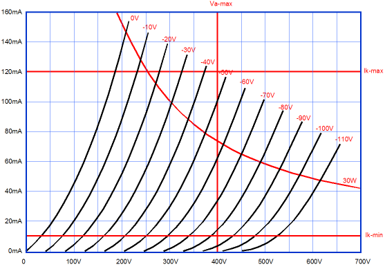
When designing any type of tube-based power amplifier, whether that design process takes place on a paper-pad or in SPICE, we should examine the tube's plate curves. This set of plot-lines reveal how much current flows at a given cathode-to-plate voltage with a given grid voltage, with cathode-to-plate voltage smoothly ramping up, while the grid voltage jumps in fixed-voltage steps. This is fantastically useful information, although it tells us nothing of such desired attributes such as "drive" and "punch" and the all important "slam." These can only be discerned by talking to several audio salesmen and accruing bigger credit-card debt, although you might try reading tea leaves or assessing the entrails of sacrificed birds. (If you are applying for a government grant, refer to it as Hepatoscopic Heuristic for Preauditory Sequacious Cyrenaic Evaluation.)
Since many readers expect me to say that when designing a power amplifier we must start at the end, I won't disappoint them; start at the end. We know instantly that since 0.2A against 50 ohms equals 10V, the B+ voltage must exceed 20V in a Futterman style totem-pole OTL and +/-10V in a totem-pole that uses a bipolar power supply. This is the starting point with imaginary perfect output tubes that exhibit an rp of 0 ohms and gm of infinity. Until our politicians get around to passing a law mandating the creation of such an output tube, we will have use actual tubes. We array the usual suspects, such as the 6AS7, 6BL7, 6BX7, 6C333, 6H30, 12B4, EL509… We then examine the 0V grid plot line for each tube and find the plate voltage that intersects the 200mA current line. Or put differently, we find the required plate voltage that allows the tube to conduct 200mA. We then make a list.
In terms of striving for the lowest possible B+ voltage and the fewest triodes, the clear loser is the 6BL7 and the clear winner is the 6C33. If we are willing to place multiple triodes in parallel, then even the 6BL7 could be used, as four 6BL7 triodes in parallel will give us our desired 200mA with a reasonable cathode-to-plate voltage of 130V plus 10V. Why plus 10V? Do not forget the 10V dropped across the 50-ohm load, as this 10V must be added to the cathode-to-plate voltage. We can now apply other criteria, such as tube cost, tube sexiness, heater current draw, tube size, tube amplification factor and transconductance and plate-dissipation limits… looking over this list of possible output tubes, the 6AS7 and 12B4 are likely to the prove the best candidates. One 6AS7 per channel would do it, as would four 12B4 tubes per channel—the difference being that 6AS7 holds two triodes; the 12B4, one triode. (One tube that didn't make the list was the 2A3, which was perhaps a mistake. If we include triode-connected pentodes, such as the EL34 and EL84 and EL86, the list grows much longer in number.)
The 6AS7's heater requires 15.75W of power; the four 12B4 heaters, 15.12W; in other words, close enough to be a draw. Assuming class-A push-pull operation, the two 6AS7 triodes realize a combined transconductance of about 17.7mA/V at an idle current of 100mA and a cathode-to-plate voltage of 60V. In contrast, the four 12B4 bring in a combined transconductance of about 39.3mA/V at an idle current of 50mA per triode and a cathode-to-plate voltage of 90V. The 6AS7 will dissipate 12W at idle per channel; the 12B4, 18W, due to the higher B+ voltage needed. So which is the better choice?
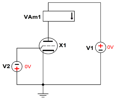
I would go with the 12B4s, as the more than two times bigger transconductance will greatly unload the OTL amplifier's input and phase splitter stages. At the same time, the 150% great B+ voltage required by the 12B4, which resulted in the 150% greater heat dissipation, is the price we paid for the more than doubled transconductance. On the other hand, almost everyone will agree that a 6AS7 is far sexier looking than a 12B4. (I have been told that since a 6AS7 looks like a 2A3, it must sound like one.) Well, no doubt this has been my longest preamble/throat-clearing ever. But as my goal is to allow you to think like a circuit designer, not to force a circuit on you, the long introduction is just as educational as what will follow. We return to the beginning and my telling of my being stunned by just how well the SPICE simulations of the 6C33C-based circuits turned out. The first rule in SPICE simulation is to make sure your SPICE models actually model reality. A good rule. Now every SPICE tube model I have seen is far too optimistic. For example, none model positive grid current and most assume triodes with perfectly constant amplification factors (mu). Real triodes, even the 300B and 845, exhibit a varying amplification factor. Is this an important failing? It is if you are doing distortion analysis, as a constant amplification factor can result in zero distortion in SPICE simulations, which reality will certainly fail to deliver. I decided to test the 6C33 SPICE model by placing it in a virtual curve tracer. To make SPICE curve tracer you only need two voltage sources, a current meter, and triode to test. (I always add a fifth part, the ground, only because SPICE likes there to be a ground in each circuit.)
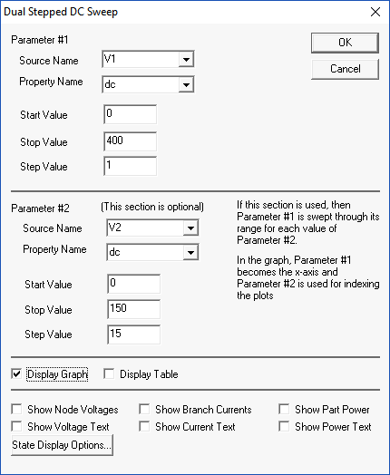
Voltage source V1 serves as the variable B+ voltage and V2 serves as the stepped grid-voltage generator. Note that V2 is seemingly inserted upside down; it isn't. The SPICE test we perform is called a "Dual Parameter DC Sweep," which allows us to generate a set of plate curves from a SPICE tube model.
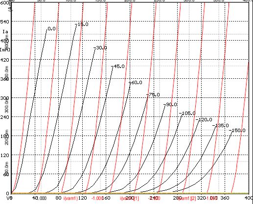
We set V1's starting voltage to 0V and its ending voltage to 400V; we then set V2's starting voltage to 0V and ending voltage to -150V. V1's step increment is set to 0.1V and V2's to -15V. The SPICE engine then runs 44,000 sequential simulations. (Are you not glad that you do not have to run each separately?) The SPICE program then plots out all the results in the set of plate curves you see below.
Very pretty, but how accurate are these curves? Here the SPICE-generated plate curves are overlain upon the 6C33's actual curves derived from a curve tracer, which I found at the Audiomatica website.
The madness of simulations or as the Ghost might have said in the play Hamlet,
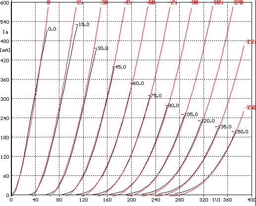
SPICE models can be bad in two ways: overly pessimistic and overly optimistic. The pessimistic model is vastly better than the optimistic model, as it is better to build an actual circuit and be pleased to find that reality outperforms SPICE simulations than to be disappointed by reality. Few utterances are sadder or lamer than, "But it worked fantastically well in SPICE." Okay, returning to the 6C33 SPICE model, note the implicit assumption of a constant mu and the gross overestimation of transconductance. If such a triode existed, it would instantly become the new standard by which all other tubes and soilid-state devices would be judged, and invariably found wanting, as this SPICE model implies a triode with zero distiortion. You might be wondering how my own True Curves math model of the 6C33 compares to the curve tracer-generated plot lines. Here is the answer.
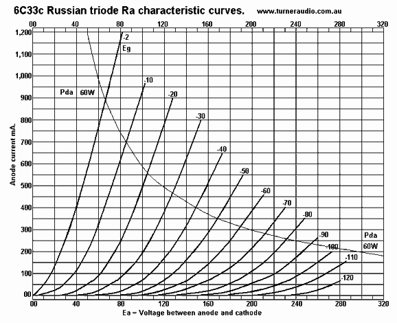
Nuff said? Yep. Actually, here is a further wrinkle. Here is a competing set of plate curves for the 6C33 from the Turner Audio website.
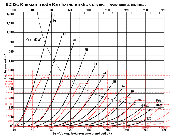
Before I go any further, I highly recommend that you read the entire OTL page at the Tuner Audio site. He makes many valid points. So, where did this set of curves come from? How accurate are they? Why does the first plot start at -2V, not 0V? I decided to overlay the real curve-tracer plotlines atop the image above.
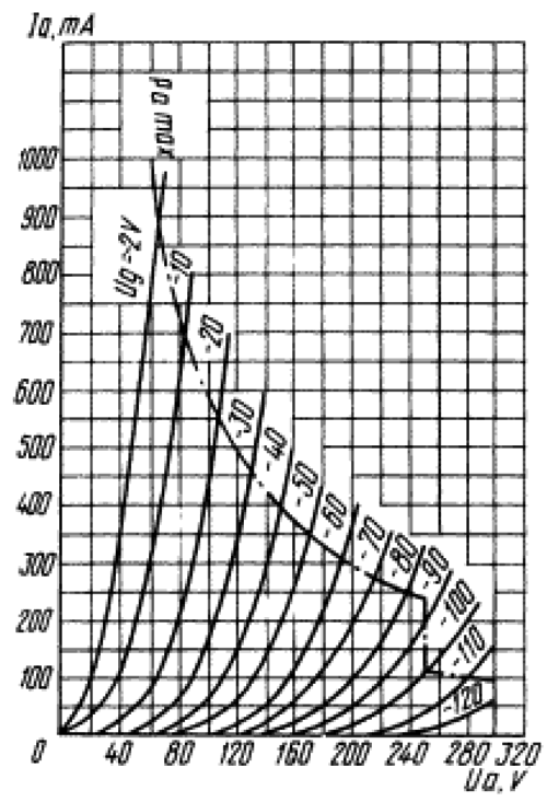
One small problem we face is that the red lines from the real curve tracer are arrayed in -15V decrements, while the image uses -10V decrements. The problem is small, as every other line should overlap. They don't. I went searching for other sets of curve for the 6C33C. Here is what its data sheet shows:
Note that it, too, extends from 0V to 320V, from 0mA to 1200mA. Both graphs first plot line is at -2V and both graphs decrements are in -10V steps. Both graphs X axis use a 40V spacing in voltage marking. If you examine a few points, you realize that the pretty graph was derived from the ugly graph. Is this a problem? It can be. Here is why: tube curve tracers are rare, particularly one that can handle 1A of current flow. In fact, prior to the mid fifties, they were not commercially made. Yet, tube manuals, even ones from the 1930s, are filled with plate curves. A paradox. No, not really. Here is what I said in post 48:
Check this post out, as it, too, deals with bad SPICE models. How do we know that the actual 6C33 that was used in the actual curve tracer was actually representative of most 6C33 tubes? The key word in that last sentence was "most." Note that I didn't use the word "all," as no 6C33 can be representative of all 6C33 tubes, as some are broken, spent, deformed, NOS, factory rejects... The average height of Chinese men varies from 5'6' to 5'9", depending on which part of China you evaluate. Yet, the world's smallest man and tallest man are both Chinese. In a college library, I once saw the most interesting book, as it was filled entirely with plate curves of commonly-used tubes. What made it fantastically interesting was how the curves were derived. They had placed a big number, say 20, of the same tube, but from different years of production and from different manufacturers in parallel. A curve tracer then made the plate curves for the group and the Y-axis was scaled down by a factor of 20. What we saw then was a set of plate curve that might not have matched a single 12AX7, but which could be seen as being more accurate than any single 12AX7 set of plate curves taken from one 12AX7. Never forget that tubes are just as much mechanical structures as they are electronic devices. What to do? The 6C33C SPICE model stinks, so we won't use it anymore.
Or, maybe, we do. If we use it, we do so in the complete knowledge that it stinks. But, John, since it stinks, we cannot trust any of the results. Often we use SPICE, not to find exact results, but only as a proof of concept. What this stinky 6C33 model does prove is that if there were such a triode, it would yield the great results that SPICE arrayed before our eyes.
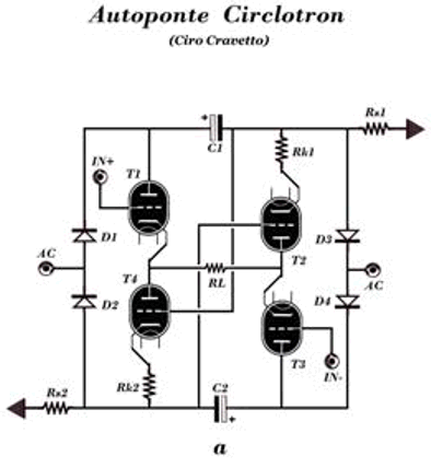
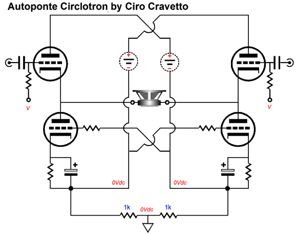
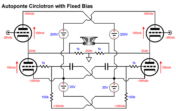
Autoponte Circlotron
The circuit paradoxically looks both super simple and super complex. I got dizzy from looking at it, so I sketched it out on a sheet of paper and then it only looked super simple.
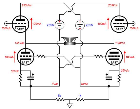
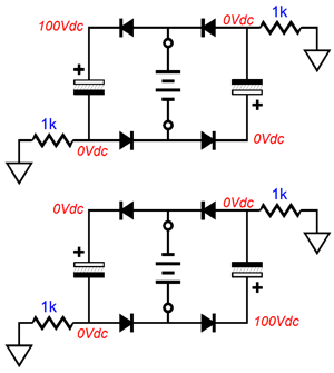
I removed the rectifiers and power-supply capacitors, replacing them with two floating power supplies. I added input coupling capacitors and cathode-resistor shunting capacitors. Now let's add some voltages and tube types.
Just like the conventional circlotron, the Autoponte requires a balanced input signal. The speaker sees no net DC voltage across its terminals, so it is safe. Each triode draws 100mA. The bottom triode grids are cross-coupled to the other sides. The result is that all the triodes see a balanced input signal.
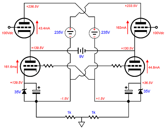
To better see the how the voltages interrelate, let's replace the loudspeaker with a 9V battery and run some SPICE simulations. (I replaced the cathode resistors with 35V zeners to make the DC voltage relationships more obvious.)
Both top triodes see a 4.5V change in their cathode-to-plate voltage. In contrast, both bottom triodes only see a 3V change, which explains the break in symmetry, the 161.6mA in contrast with 163mA, 43.4mA versus 44.8mA. If we flip the battery, we flip the voltages. In either position, the battery sees a current flow 118mA, which implies an output impedance of 76 ohms (divide the 9 volts by the current flow). We can eliminate the cathode bias feature and move the ground connecting 1k resistors to the top.
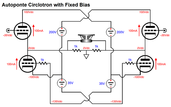
Now, the outputs are at ground potential and you no longer have to wear rubber gloves as you attach your speakers to the amplifiers. Instead of two floating power supplies, we now have four. We could eliminate the two coupling capacitors, if we wished.
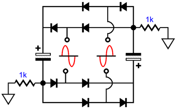
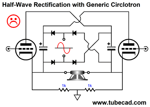
It's simpler, but I don't recommend it. Why not? The coupling capacitor and grid resistor form an RC low-pass filter to the power-supply ripple present at the bottom of the 35V floating power supplies. In contrast, the direct coupling also couples all the power-supply ripple, which in Mr. Cravetto's design will be considerable and unbalanced between sides, as half-wave rectification is used. Speaking of the power supply in the Autoponte circlotron, here it is.
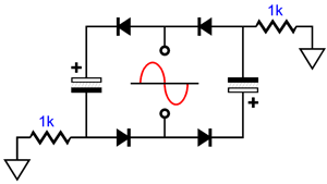
We can redraw the circuit, making it a tad less confusing.
The AC voltage will charge up one capacitor at a time; thus it is a half-wave rectifier circuit. Because rectifiers are cheap, the half-wave rectifier circuit is rare these days. Moreover, half-wave rectification can cause transformer problems, such as magnetizing the transformer's core. In the Autoponte circuit, however, the transformer secondary will not saturate, as it never experiences repeated unidirectional current flow, as each half of the AC sine wave gets used. In other words, the transformer core believes its is being called upon to deliver full-wave rectification; but as far as each capacitor is concerned, it is being charged only on every other half wave. As each capacitor will be only half-wave rectified, its ripple frequency will be the same as the wall-voltage frequency, 60Hz in the USA; 50Hz, Europe. To see how this result obtains, let's use a high-voltage battery in place of the AC voltage.
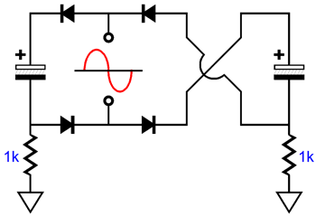
As we can see, depending on the battery position, either the left or the right capacitor charges up, but not both at once. Okay, what's the workaround? If we add an additional secondary winding, we can realize full-wave rectification.
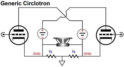
Now the ripple will match across both capacitors and the ripple frequency will be at twice the wall-voltage frequency. Genius? No, it's actually a giant step sideways, as the two secondaries bring us back to the conventional circlotron's two full-wave-rectifies floating power supplies. Speaking of the conventional circlotron, how does the Autoponte circlotron compare?
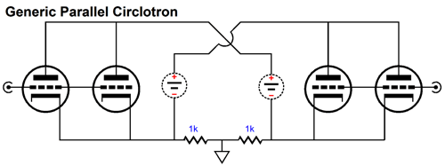
Well, in order to compare apples to apples, we must double up on triodes first.
I ran several SPICE simulations on both circuits and here are the results.
The limit imposed was that of class-A operation. In other words, 22Vpk of AC input signal was the most the Autoponte could handle before some of the triodes cut off. Placing two 6AS7 triodes in parallel effectively made the 32-ohm load impedance appear twice as large to the triodes in the conventional circlotron, so the load line sloped less steeply, which explains why it could handle 30Vpk before departing class-A operation. In terms of gain, output impedance, power output, distortion and PSRR, the conventional circlotron wins. Note that the conventional circlotron's PSRR is intrinsically stellar, assuming a matched set of tubes; the better the match, the better the PSRR. While matched triodes are also needed for the Autoponte circlotron, its PSRR is naturally weak due to the half-wave rectification. With full-wave rectification, its PSRR would also prove great. Not what you expected? It wasn't what I expected, as I expected the Autoponte to only perform slightly worse, not substantially worse. Why? The Autoponte's bottom triodes are lazily hanging on to the top triodes. And while the bottom triodes do make some contribution to the output signal, they do so far less efficiently than would two extra triodes in parallel with a conventional circlotrons two output triodes. Here is the conclusion in a nutshell: a bridge amplifier makes so much more sense with solid-state devices, which are often voltage limited, but not current limited. By holding two internal power amplifiers that put out a differential output, the bridge amplifier offers four times the output wattage, twice the slew-rate, and twice the output impedance that one amplifier with the same power-supply-rail voltages would. In contrast, vacuum tubes are seldom voltage limited, but are nearly always current limited, so a bridge configuration only makes sense with high-impedance loads, not brutally-low load impedances. I have written a lot about bridge amplifiers; paste the following into a Google search box to find some of it, "bridge amplifiers site:tubecad.com" Before leaving this topic, I should point out that we can use Mr. Cravetto's half-wave rectifier circuit on a convention circlotron.
It would work, but I do not recommend it, as the PSRR will suffer the same fate as the Autoponte circlotron, for the half-wave rectification ripple does not null between sides. So, Ciro, thanks for the circuit, but I cannot see it as an improvement.
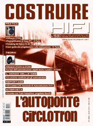
If you have access to the Italian audio-construction magazine, Costruire HiFi, look for the issue shown above, as it contains an article on his design.
Music Recommendation: Young Voices Then as a teenager, I listen to young men who sang with old voices, such as Ian Anderson, Joe Cocker, Leonard Cohen, Dylan, Van Morrison, Tom Waits—all sounding vastly older than they were. In college, the Blues took hold of me and I enjoyed hearing the old singers sound old, my favorite being Howling Wolf (Chester Arthur Burnett). Then as audiophile obsessions won me over, I added many female singers to my LP collection, such as Janis Ian, Janis Joplin, Joni Mitchell, Linda Ronstadt, Patti Smith... As we age, our voices lose agility and our highs dull. Thus, an agile and bright-sounding singer will sound young, even if not young. A good example was Ella Fitzgerald. Another is Paul Simon, who at 76, sounds shockingly younger than he is. Apart from technical issues, the suggestive and emotional overlay imparted by a young voice gives the singing its own flavor. For example, in spite of how nasty boys are in general, boy choirs sound, to my ears, tenderly innocent if not angelic. Since boy choirs are so rare these days (and might soon become illegal in goofy places like the USA, Canada, Australia, New Zealand, and much of Europe), women choirs are often called in to take their place; and while the women technically out perform the boys, our ears and souls are cheated. Mahler's Third and Eighth Symphonies included boys choirs, but in the performance of these, I have only heard women choirs in concert halls. I have attended at least four performances of Carl Orff's Carmina Burana, but only one used a boy choir and it was revelatory. Hell, even Tchaikovsky's Nutcracker Suite demands a boy choir to achieve magic. Young-sounding female singers bestow a different emotional overly. Even when they sing of their broken hearts and shattered life, their youthful-sounding voices lend an optimistic and sunny flavor. Here is my quick list of young-sounding female singers: Erin Bode, Julie Byrne, Aoife O'Donovan, Kina Grannis, Sara Lov.
In the center, Julie Byrne gets the biggest photo. I was hesitant to include her in this list, as she isn't a perfect fit. Sure her young voice does sound young, but her voice isn't in least flashy, sounding as if she could show off, but wisely chooses not to. Moreover, her songs tend to probe deeper into existence than other young singers can even imagine, let alone desire to search out. In short, her good sense belies her years. In other words, she is a young singer with some older-singer overlay. As wisdom and youth are brought together as seldom as flexibility and old age are, I am eager to hear what she will bring out in her next decade of life. All the rest definitely sound young. For example, I bet that when Aoife O'Donovan answers the phone, she is often asked if her mother is home. Erin Bode (her surname is pronounced as two syllables with long vowels, bō dee) is my first choice when I need to feel happier. She doesn't fit neatly in any genre, being something of jazz singer and pop singer at once. And Kina Grannis and Sara Lov are good second choices. By the way, all of the above albums are audiophile grade. So, what are you waiting for? Go to Tidal and see the many albums that Tidal offers for each singer.
Tidal Music Service is the Netflix of lossless music. If you are already a subscriber to Tidal, it cost you nothing but time to give a recommended album a listen.
//JRB
*Grandiloquent Diction True enough, I had a few amazing dreams and I even designed a circuit in one. My guess is the sickness weakens the critical portion of my consciousness enough to allow the more imaginative portion to run wild. Normally, if my dream strays too far beyond the limits imposed by logic, reason and reality, I call BS within the dream and quickly awake. Aldous Huxley wrote something similar in his short book, The Doors of Perception: "Only when I have a high temperature do my mental images come to independent life." Well, with half my brain clogged up, the grandiloquent diction just pours freely into my fingertips, which is something I usually try to avoid, as I know such esoteric words will nettle nineteen out of twenty readers. (See, I just did it again. "Nettle" when used as a verb and not a noun means to irritate or annoy. Use a word like "moil" —hard work and to be in continuous agitation [it is the last half of turmoil after all]— or "pavid"—quaking with fear—more than twice a year and people will complain. Maybe only twice per decade is what polite company will forgive but never excuse. Note that neither word is long. The world needs a new book: Little Big Words Few Know. In this book, no big word could be longer than four letters long.) What about that twentieth reader? These words will tickle him and he is just the sort of reader who is more likely to offer to buy me a drink when we meet at an audio event. A utilitarianism nightmare. One good thing did come out of this illness: one night, I found that I couldn't move my head without making it hurt. I dug out Milton's epic poem. Paradise Lost, and read the first book. It was great, far better than I remembered from my reading of it 40 years ago. The secret is to be much older and read it with an enraged voice in mind.
User Guides for GlassWare Software
For those of you who still have old computers running Windows XP (32-bit) or any other Windows 32-bit OS, I have setup the download availability of my old old standards: Tube CAD, SE Amp CAD, and Audio Gadgets. The downloads are at the GlassWare-Yahoo store and the price is only $9.95 for each program. http://glass-ware.stores.yahoo.net/adsoffromgla.html So many have asked that I had to do it. WARNING: THESE THREE PROGRAMS WILL NOT RUN UNDER VISTA 64-Bit or WINDOWS 7 & 8 or any other 64-bit OS. I do plan on remaking all of these programs into 64-bit versions, but it will be a huge ordeal, as programming requires vast chunks of noise-free time, something very rare with children running about. Ideally, I would love to come out with versions that run on iPads and Android-OS tablets.
//JRB
|
|
John Gives
Special Thanks to the Special 68
I am truly stunned and appreciative of their support. In addition I want to thank
All of your support makes a big difference. I would love to arrive at the point where creating my posts was my top priority of the day, not something that I have to steal time from other obligations to do. The more support I get, the higher up these posts move up in deserving attention. Only those who have produced a technical white paper or written an article on electronics know just how much time and effort is required to produce one of my posts, as novel circuits must be created, SPICE simulations must be run, schematics must be drawn, and thousands of words must be written. If you have been reading my posts, you know that my lifetime goal is reaching post number one thousand. I have 578 more to go. My second goal is to gather 1,000 patrons. I have 932 patrons to go. Help me get there.
Only $12.95 TCJ My-Stock DB
Version 2 Improvements *User definable Download for www.glass-ware.com |
||||||||||||||||||||||||||


| www.tubecad.com Copyright © 1999-2018 GlassWare All Rights Reserved |