| John Broskie's Guide to Tube Circuit Analysis & Design |
22 June 2018 Post 429
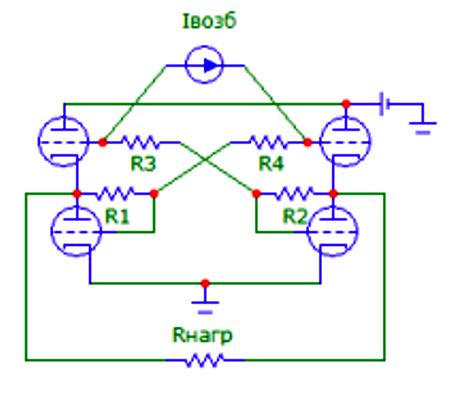
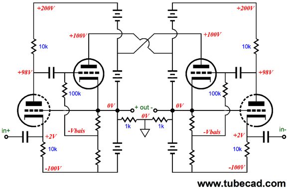
More Russian Circlotrons (I once had a spy at National Semi, before Texas Instruments bought them, who used to send me inside info on audio products under development. I had been pushing for them to create a unity-gain power buffer in the same package as the LM3886.) Although this first Russian circuit accepts a balanced input signal and puts out a balanced output signal, this circuit is not really a circlotron.
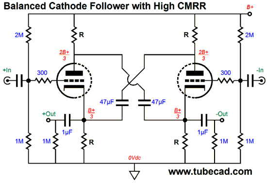
What have here is a push-pull balanced buffer, with each side's top and bottom triodes working in current anti-phase. If it looks familiar, it is due to a similar circuit appearing here back in 2012 in post 246.
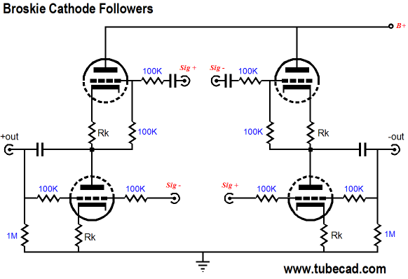
My circuit works by carefully selecting the cathode resistor value to ensure balanced current swings from the top and bottom triodes. In contrast, the Russian circuit uses two feedback loops in an attempt to make the bottom triode behave as anode followers, so their current swings and output impedance match the top cathode followers. A better approach is to go the full monty, or is the full Broskie, and use balanced Broskie cathode followers (BCF).
The added four 100k resistors equalize the top and bottom followers. See post 189 for more information on how it works. A closer approximation to a true circlotron can be found in post 371.
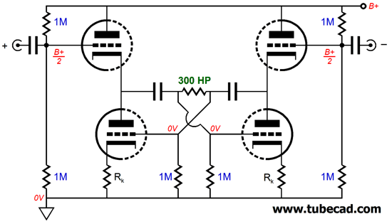
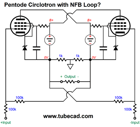
The two crisscross coupling capacitors bridge, in AC terms, cathodes and plates, much like the two floating power supplies do in a true circlotron output stage. Asides from DC currents, the big difference between the two is that this AC circlotron must be operated in strict class-A, whereas the true circlotron can be operated in a in anything from class-C to true class-A. The next Russian circlotron circuit uses triode-connected pentodes and an output transformer. To be honest, I am not sure what was the goal here. My best guess is that some sort of negative feedback loop arrangement was sought.
I will now redraw the schematic and switch to a pentode configuration of the output tubes and eliminate the potentiometers and inductors by using zenrs to cathode bias the pentodes.
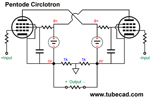
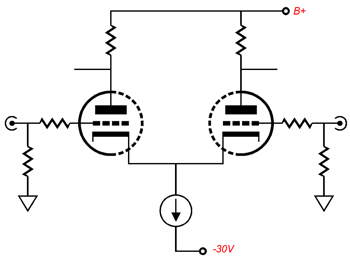
I believe this is what was the goal behind the original. If so, how well does it work? Since so little gain is realized, if any at all, I don't see how this negative feedback setup can yield any real results. And just in case you were wondering, does the conventional circlotron deliver any voltage gain at all? It does and, under ideal conditions, it yields a gain of two. But as 8-ohm loads are nowhere near ideal loads for any tubes, we usually end with a gain far below unity. Before going any further, I should point out that at least three ways exist to arrange a pentode output tube. The first is a pentode.
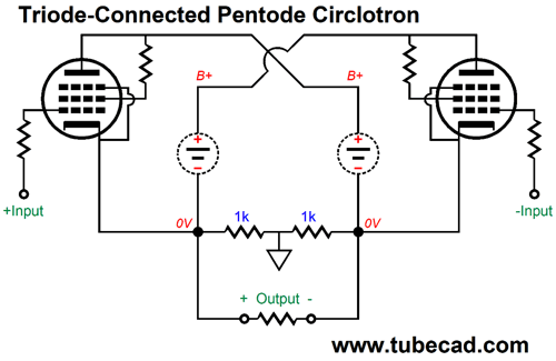
The screen (grid-2) attaches to the B+ voltage through a resistor, usually 1k to 10k, depending on the pentode used. In a circlotron that DC couples to the speaker, the most likely pentode to be used is the EL509. The second arrangement for the output pentodes is triode-connected, where the screen attaches to plate either directly or through a 1k resistor.
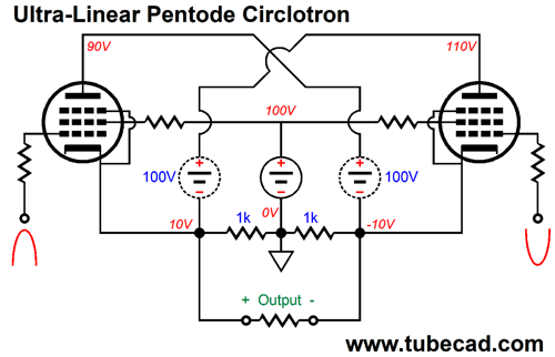
The pentode now behaves as a triode and exhibits plate resistance and a fairly low amplification factor. The third arrangement is a form of ultra-linear, where the screen sees only a percentage of the plate-voltage swings.
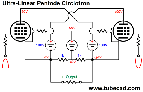
In the example above, the screen (grid-2) sees 50% of the plate-voltage swings. I know that this will be hard to understand, but the secret is to normalize all the voltages relative to one cathode. Let's start with all voltages relative to ground, while the left pentode sees a positive input signal and the right pentode sees a negative signal.
The loudspeaker sees a peak voltage swing of 20V, as the left pentode's cathode is at +10V, while the right pentode's cathode is at -10V. Now, let's normalize the voltages to the left pentode's cathode.
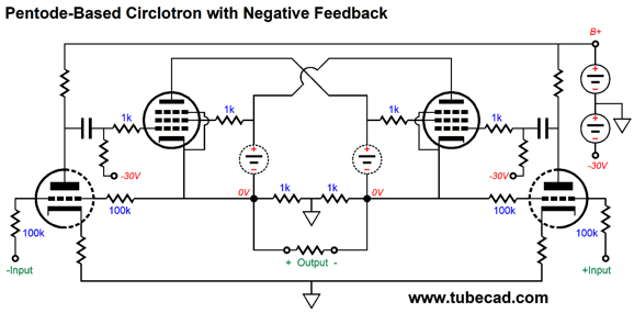
Note that the plate voltage has fallen from its idle value by 20 volts, but the screen voltage has fallen by only 10 volts, or 50% of the plate's 20-volt negative swing. Okay, let's now return to the idea of applying a negative feedback loop to the output stage. For negative feedback to work, we need excess open-loop gain. By adding two extra triodes we can get plenty of extra open-loop gain.
The left triode controls the left pentode, while the right triode controls the right pentode. If the balanced input signal is hot enough, i.e. large enough in voltage swings, this might be enough to drive a loudspeaker, assuming many pentodes in parallel. Most, however, would add an input stage to provide the needed drive signal.
The differential amplifier with the constant-current source cathode loading will provide a fairly good balanced output even with an unbalanced input signal. On the other hand, the inverting-amplifier negative feedback arrangement has its own problems, such as less negative feedback than a comparable non-inverting arrangement, as the two 100k negative feedback resistors define a 50% signal attenuator, so the triode grids only see half of the perturbations at the pentode cathodes that they might otherwise see, In addition, the large-valued negative feedback resistors will interact with the triode's Miller-effect capacitance. Moreover, these resistors should be driven by a low-impedance signal source. In post 251, I showed how a grounded-grid amplifier could be used to apply a negative feedback loop around the output tubes.
In this arrangement, the grounded-grid amplifier's grid sees 100% of the output tube's deviations from the desired output. In this setup, the grounded-grid amplifier cathodes are far easier to drive than you might expect, due to the cathodes following the grid in the grounded-grid amplifier. The last Russian circlotron circuit a setup somewhat similar to the above schematic, as the input pentode screens are used as negative feedback ports.
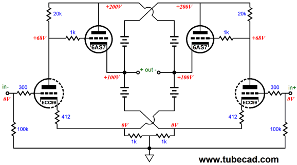
This original schematic was a screen capture for a SPICE program and some might not recognize the output transformer from the schematic. Here is my redrawing of the circuit. (I had to guess at some of the voltages.)
As we can see, DC coupled input pentodes drive output pentodes, with transformer coupling to the loudspeaker. Two floating power supplies are used per channel and one fixed power supply can be used per channel or shared between two stereo amplifiers in one chassis. This circuit reminds me of one of my designs from post 251.
So, what are we to make of this all-pentode, Russian design? No doubt it will work well in SPICE simulations, but I worry about reality. Why? DC coupling. In SPICE, we can get matched plate voltages within a millionth of a micro volt; reality laughs at us, making a 10-volt match a huge achievement. And imagine that the input pentodes are cold and not conducting or are missing from their sockets. What happens, as the output pentode grids are effectively attached the the B+ voltage? It cannot be good. And since I hate melted output tubes more than I hate coupling capacitors, I would add two coupling capacitors and use a cross-coupled garter-belt grid-bias arrangement to eliminate a DC from developing across the output transformer primary. Indeed, with coupling capacitors in place, we could probably lose the 200V fixed power supply
Note how input pentode screens still see 200V. Also note how the input pentode differential amplifier now uses a constant-current source rather than a 92-ohm common resistor. Two floating power supplies are still needed, but their voltage could be a low 100V, say that EL86 output tubes were used, or a high 500V, say that KT120 output tubes were used. We can add lots more bells and whistles to design above, but I would prefer to try something different with the output transformer.
Single-Power-Supply Circlotron with Output Transformer
But what should we do with the ultra-linear taps on the output transformer's primary? One possibility is to use them by attaching them to the screens, after adding a second set of cross-coupled capacitors. Another possibility is to use them as negative feedback AC signal dividers for the driver stage.
The driver tubes receive negative feedback signals at both their cathodes and plates, with the cathode signal proving the stronger, as it will be amplified by the driver triode. Without the crisscrossing capacitors this arrangement would not work well once the output stage left the class-A window of operation. But with the capacitors in place, the two entire primary windings are completely engaged. In a normal tube-based transformer-coupled output stage, once one power tube cuts off, half of the primary is left dangling and the still active output tube sees it load impedance double. In contrast, in this arrangement all of the primary is always engaged, so no flapping in the wind. I didn't show cross-coupled capacitors that would bridge the top and bottom ultra-linear taps, as the schematic was already dangerously to complex. So, it will be up to you to imagine that the following applies to the previous and following schematics.
We need these capacitors to be large enough in value to act like floating power supplies for audio frequencies. Since the ultra-linear taps establish a far lower winding ratio with the secondary, the impedances they cross-couple will be far lower than the capacitors that cross-couple the ends of the primaries. For example, if the UL taps are at 50%, then the load impedance they see will be one fourth what the outside capacitors see. In other words, the inside capacitors should be larger in value than the outside capacitors. If we use pentodes as the output tubes, we can use the UL taps, as shown below.
By the way, I left out grid stopper resistors to make the schematic more "readable," but they are absolutely essential in an actual output stage. The pentode output tubes use fixed bias to establish the idle current and their screens attach to the UL taps. The driver triodes nested in the center will need to see a large balanced input signal. In fact, one worry I have is that the driver triodes may not be able to provide a large enough plate-voltage swing to drive the output pentode and may have to terminate their plate resistors directly into the B+ voltage or even some higher voltage—or even the other UL taps, which will produce some postive feedback. Of course, much depends on the UL ratio. If it is 50% or 33%, worry; if it is 10% to 15%, only worry a little. Also, much depends on the output tubes used. If 300B tubes are used, worry a lot; if EL84 or EL86 or 8417 pentodes are used, worry very little. The same goes for using high-voltage N-channel MOSFETs, as they require very little drive voltage. By the way, normally a solid-state device would have a tough time replacing a triode or pentode in a conventional, transformer-coupled, push-pull output stage, as wild, huge inductive-induced voltage spikes can develop when one output device cuts off and half of the primary is left unloaded. In contrast, this quasi circlotron arrangement tightly locks both primaries, so nothing is ever left blowing in the electron wind. I would use the 16-ohm secondary taps and the ground tap to connect to an 8-ohm loudspeaker, as it will yield the lowest winding ratio and allow the biggest output voltage swings. Since the two output transformer are working in parallel, we might be able to get twice the output power. I wrote "might," as the math must work out. Let's say that two Dynaco ST-70 output transformers are used per channel. Each is rated for 35W, so if the math broke in our favor, we might get 70W from the two. Here is some math: 70W into an 8-ohm load requires 33.5Vpk. The P-470 transformer presents a primary impedance of 4300 ohms, which equals a winding ratio of 16.4 : 1 between primary and entire secondary (16-ohm tap to ground) . Multiply 33.5V by 16.4 and you get about 550V. In other words, to develop 33.5Vpk on the entire secondary, from 16-ohm tap to ground tap, requires that the primary sees a voltage swing of 550V, from end to end. Since the primary is center-tapped, one end would swing up to 275Vpk, while the other end would swing down to -275Vpk. This doesn't seem too bad, but it is; if the other primary that sits at 500V at idle and one end swings down to 225Vpk, leaving only 225V - 275V or -50V for one output tube and developing a 775Vpk + 275Vpk or 1050Vpk across the other output tube. I do not worry too much about the higher voltage, but I do worry about the impossible -50 volt cathode-to-plate voltage on the other output tube. In other words, we need a higher B+ voltage. Even with a scary 600V B+ voltage, we might not have enough headroom, as the extra 100V only gives us a 50V cathode-to-plate voltage for one output tube at full output. In order for a triode to develop needed current flow of 256mA to create a 550V voltage drop across a 2150-ohm impedance, the triode's plate resistance must be a low 195 ohms, far lower than most audio output triodes. The KT120 or KT150 might be able to pull it off without going into positive grid current conduction, but not with the ultra-linear connection, only with the screens attached to 500V off of the 600V B+ voltage in the pentode arrangement. Math can be mean. In other words, even with huge output tubes, we may only get 40W of output. Is that a tragedy? No. In fact, I will always take quality over quantity. Another workaround is to place the two secondaries in series, not parallel.
Now we are presented with many more options, as we have all those secondary taps to play with. For example, if we place a loudspeaker across the entire two secondaries, the winding ratio falls to half, 8.2 : 1. To find the impedance ratio, we square the winding ratio, which in this example will give us 67.24 : 1. Thus, an 8-ohm load will reflect to the primary as 538 ohms. To get the needed 33.5Vpk for 70W into 8-ohm loads the primary must see 33.5Vpk x 8.2 or 275Vpk; in other words, half of the previous value. Now we have voltage headroom galore, but we have doubled the needed current swings. No free lunches ever. How much peak current swing is needed? Just divide 275V by the primary impedance, which in this example would be 275V/538 or 511mA. With a 400V B+ voltage and two to four output tubes, this much current should be obtainable. I would look into using a pair of EL509 or four KT88 pentodes. In fact, using high-voltage power MOSFETs might be the best route to follow. If nothing else, we can lose the negative power-supply rail.
Note how the two-resistor voltage dividers terminate into ground, not the MOSFET's source. Why? We are using the primary DCR as part of the biasing scheme to set the idle current. In other words, we are turning a transformer liability into a feature, as we can use the primary DCR in establishing a source resistance to bias the MOSFETs with. The P-470 transformer's primary DCR is about 190 ohms, with about 100 ohms from one end to the center-tap and 90 from the other end to the center-tap. Why the difference? A transformer is based on windings of wire. They wind so many turns of wire, then bring out a center-tap and then wind the same number of turns of wire, but this half of the primary will be wound over a fatter bobbin due to the first half of the primary being already there. The result is that although the same number turns are made, the length of wire needed is greater, which results in a higher DCR for the second half of the primary. We need to take in account this discrepancy when setting up the bias voltage for the MOSFETs. Another issue I must mention is the assumption that music will be amplified, not test sine waves. Music is seldom continuous; instead, it swells and relapses. In contrast, a sinewave generator puts out a steady, unrelenting sinewave. My worry is that the crisscross capacitors will either discharge or over charge with sustained full power output for ten minutes. In contrast, true floating power supplies could go the distance. If we place the two output transformers in actual parallel, without the criss-crossing capacitors and use two floating power supplies, we can greatly unload the output transformers.
Note that no current flows through the primaries at idle, so they will not be needlessly heated. Note that I am using two output transformers because I want a lower winding ratio. Of course, if a custom transformer were made, it could be a single unit. While I am at it, I should stress the great advantage of a circlotron circuit: it uses the same output device throughout. In a typical solid-state output stage, power NPN and PNP output transistors are used. In theory, they are complementary; in reality, they aren't really. In addition, the reason an output transformer makes sense in this circuit is that we want to run the driver tubes from the ultra-linear taps. If that is not our goal, the transformer makes less sense, although it does add extra protection for the loudspeaker.
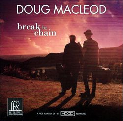
Music Recommendation: Doug Macleod John Lennon famously said, "Before Elvis, there was nothing." Elvis may not have been the first white to sing black, but he was certainly the most successful to do so. Chuck Berry imported white country music into black music, which did not go over big with purists in Harlem. In other words, things quickly get muddled. For example, although jazz was undoubtedly a black invention, it was also deeply influenced by military marches, show tunes, European classical music, Christian hymns and church music. Well, to me the purest black musical genre is the blues. Yes, I know that there are many white bluesmen, such as Mike Bloomfield, Paul Butterfield, Eric Clapton, Bonnie Raitt, and "Stevie" Ray Vaughan—and I love all of them. Still, for me the real blues were always real black, with such greats as Robert Johnson, BB King, Buddy Guy, Big Joe Turner, Howlin' Wolf, Albert King, Little Walter, Magic Sam, Muddy Waters, Junior Wells... Now, when I first heard Doug Macleod on the radio, I thought he was black, as he sounded black to me; and I have lived in two predominately black California neighborhoods in my life, Oakland and what was once the black part of Haight Street in San Francisco (at the intersection of Ashbury Street is where the hippies lived at the time; today, neither of these two groups of people live in those two neighborhoods). Then one day I saw a picture of Macleod and I was somehow disillusioned. He didn't look a thing like Keb Mo, standing on the left in the picture below; instead, he looked exactly like the guy on the right, which makes sense as that is him. His appearance was so at odds with my mental image of him that I felt deceived and conned.
Of course, music belongs to everyone, and do not think for a second that I buy into the insanely ugly PC notion of "Cultural Appropriation," which tells Shakespeare that he shouldn't have written his play, Hamlet, as we was not a Dane; nor Othello, as he was neither a Moslem or black; nor Merchant of Venice, as he was not a Jew. And while we are at it, why not damn him for Gender Appropriation,* filled as his plays are with women. Insanity, but popular insanity. If European classical music survives and thrives, it will be because China and Japan love it so dearly; and I thank them wholeheartedly for their appropriation, as I believe in intense cultural appreciation, which necessarily includes borrowing and blending. Moreover, I have seen polls that show that few young black Americans like either the blues or jazz. In several decades, few bluesmen will be black and most classical orchestras and soloists will be Asian. In short, I was irrationally prejudiced against Doug. (A further partial damning of him was that it seemed to me that his biggest fans were audiophiles.) With time, however, I grew to like Doug Macleod and I even used his albums for stereo demo purposes. If nothing else, he plays a mean blues guitar. Tidal offers 21 of his albums. I haven't heard all of them. The albums that I know will please audiophiles most are those on the Reference Recording label. Start with Break the Chain. which won the 2018 Acoustic Album of the Year award.
Then listen to Exactly Like This and There's A Time.
//JRB
Gender Appropriation*
User Guides for GlassWare Software Since I am still getting e-mail asking how to buy these GlassWare software programs:
For those of you who still have old computers running Windows XP (32-bit) or any other Windows 32-bit OS, I have setup the download availability of my old old standards: Tube CAD, SE Amp CAD, and Audio Gadgets. The downloads are at the GlassWare-Yahoo store and the price is only $9.95 for each program. http://glass-ware.stores.yahoo.net/adsoffromgla.html So many have asked that I had to do it. WARNING: THESE THREE PROGRAMS WILL NOT RUN UNDER VISTA 64-Bit or WINDOWS 7 & 8 or any other 64-bit OS. One day, I do plan on remaking all of these programs into 64-bit versions, but it will be a huge ordeal, as programming requires vast chunks of noise-free time, something very rare with children running about. Ideally, I would love to come out with versions that run on iPads and Android-OS tablets.
//JRB |
Special Thanks to the Special 67! To all my patrons, all 67 of them, thank you all again. I want to especially thank
I am truly stunned and appreciative of their support. In addition I want to thank
All of your support makes a big difference. I would love to arrive at the point where creating my posts was my top priority of the day, not something that I have to steal time from other obligations to do. The more support I get, the higher up these posts move up in deserving attention. Only those who have produced a technical white paper or written an article on electronics know just how much time and effort is required to produce one of my posts, as novel circuits must be created, SPICE simulations must be run, schematics must be drawn, and thousands of words must be written. If you have been reading my posts, you know that my lifetime goal is reaching post 1,000. I have 571 more to go. My second goal is to gather 1,000 patrons. I have 933 patrons to go. Help me get there.
The Tube CAD Journal's first companion program, TCJ Filter Design lets you design a filter or crossover (passive, OpAmp or tube) without having to check out thick textbooks from the library and without having to breakout the scientific calculator. This program's goal is to provide a quick and easy display not only of the frequency response, but also of the resistor and capacitor values for a passive and active filters and crossovers. TCJ Filter Design is easy to use, but not lightweight, holding over 60 different filter topologies and up to four filter alignments: While the program's main concern is active filters, solid-state and tube, it also does passive filters. In fact, it can be used to calculate passive crossovers for use with speakers by entering 8 ohms as the terminating resistance. Click on the image below to see the full screen capture.
Tube crossovers are a major part of this program; both buffered and un-buffered tube based filters along with mono-polar and bipolar power supply topologies are covered. Available on a CD-ROM and a downloadable version (4 Megabytes). |
||


| www.tubecad.com Copyright © 1999-2018 GlassWare All Rights Reserved |