| John Broskie's Guide to Tube Circuit Analysis & Design |
|
8 Aug 2018 Post 434
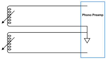
Line Stages and Kicking Butt Now, consider an electrical device that sidesteps an invisible problem: the phono cartridge. Two coils generate current, which develops an AC voltage, which the phono preamp amplifies. The two current signals travel down two pairs of twisted wire.
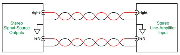
Now, consider the CD player (or tuner or tape player or stand-alone DAC). Its two channels of signal share a common-ground connection within the unit itself. The two RCA output jacks share share the common-ground connection and, at the line-stage amplifier, the two input RCA jacks share a common-ground connection within that chassis. A redundancy of grounds connections results.
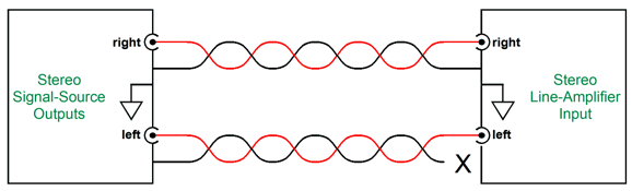
If right channel's interconnect suffered an open ground connection at the line-stage amplifier end, both channels would nonetheless play, as the left channel's interconnect would still provide a ground path back to the signal source.
In other words, only three wires were actually needed. Indeed, I am convinced that three-connector jacks and plugs would have been a far better solution to the existing RCA jacks.
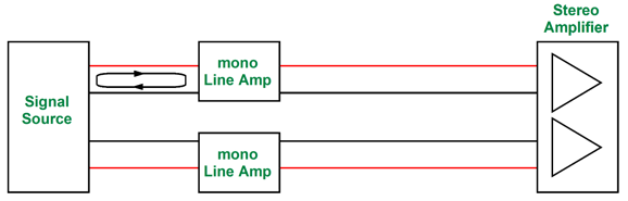
The historical problem was that mono proceeded stereo, so the mono solution was simply duplicated. So, is this redundancy of grounds connections actually a problem? I am convinced that it is. Imagine a system that held a CD player, dual-mono line-stage amplifiers, and a stereo power amplifier. Now, imagine signal flowing in only the left channel.
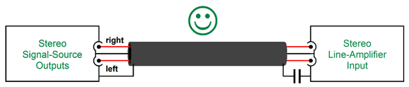
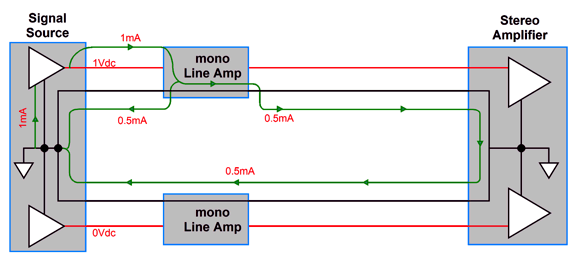
The sad face is due to reality not conforming to our expectations. Reality looks more like the following.
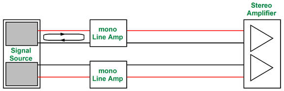
Note that the signal current leaving the CD player takes two paths back to the CD player's ground, two paths of differing length at that. In other words, all effort put into extra-fancy interconnect wire twisting and weaving is undone, as the right channel interconnect ground wire experiences the same amount of current flow as the left channel, even though the right channel is silent. Now, imagine that the CD player held two separate opto-couplers, two DACs, two separate I-to-V converters, two separate power supplies, and no common ground, but two two separate signal grounds, one for each channel. (This arrangement would mimic the phono cartridge's two separate ground wires or the use of an input signal transformer.)
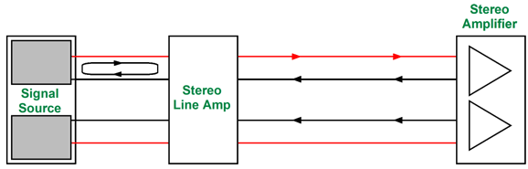
The left channel's signal remains in the left channel, with the left channel's interconnect's hot and ground wires experiencing identical current flows, while both of the right channel's wires see no current flow whatsoever. What if we use a stereo line-stage amplifier that holds one power supply; thus, one shared ground? If two monobloc power amplifiers are driven, then we are still safe.
Note how the left channel's signal remains isolated to the left channel. What if the power amplifier is a stereo design with two amplifiers and one power supply? Not so good.
The left channel's signal leaving the line-stage amplifier takes two paths back to the line-stage amplifier's ground. One workaround would be to use output signal transformers in the line-stage amplifier. Another workaround would be to use my differential input configuration in the stereo power amplifier.
Although it does not provide infinite isolation, it does come dang close (In SPICE simulations, I saw over 100dB of separation. The problem is that this solution must be implemented by the power amplifier maker. As I was looking for a schematic I had drawn, I noticed a potential trap with this scheme, a trap that I failed to spot when I covered it back in 2016, which was odd, as it is precisely the sort of trap I look out for. I was once asked how I was able to come up with so many new circuits. My answer was that two things were needed: lots of coffee and I think primarily in terms of current, and only secondarily in terms of voltage. In contrast, most think primarily in terms of voltage and seldom give current any thought. Seeing circuits through current-primary glasses give you an entirely different dimension to explore. On the other hand, looking through the voltage-primary glasses doesn't open up a new perspective and, in the worst case examples, it can lead to making some big mistakes.
For example, a friend once asked me why he couldn't use an 8-pin DIP OpAmp to drive his efficient speakers. I explained that it was too current limited. He argued that with +/-20V power-supply rails, it could put out 16V, which was more than what many single-ended power amplifiers could deliver. Once again, I pointed out that it was too current limited. He countered with the observation that offered a truly low output impedance. Once again, I repeated that it was too current limited. After few minutes of fruitless back and forth, I asked him if he knew what current was. Although he was mightily insulted, he told me that of course he did, "It's the same thing as voltage."
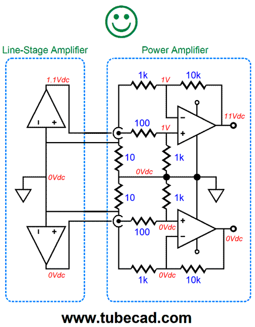
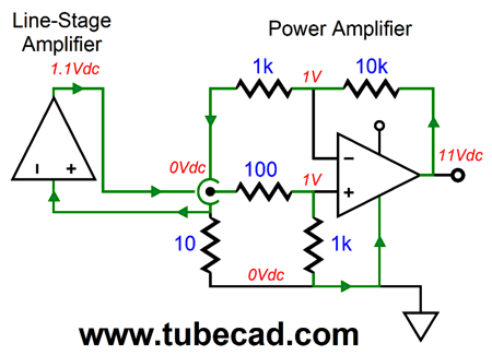
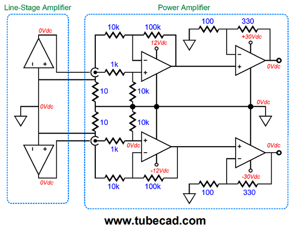
He is not alone. I wish I had a dollar for every email I have gotten that asked if my Aikido line-stage amplifier could drive a 12in woofer. (About ten dollars would have accrued and I could buy another six-pack of Odell's fine beer.) Okay, returning to the differential input on a stereo power amplifier, here is the correct arrangement.
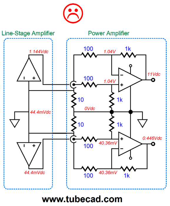
The 1.1V of DC signal leaving the top line-stage amplifier get amplified by 10 by top the solid-state power amplifier. All the DC voltage and current remains localized to the top interconnect, and no current flows through the bottom interconnect ground wire or shield. This is precisely what we want to happen. In contrast, the following arrangement of part values doesn't work.
Everything looks good, or at least it seemingly does. We even get the right amount of DC gain from the top power amplifier, but where did the big DC offset at the bottom power amplifier's output come from? In terms of voltages, all the resistors conform to the correct ratios. But in terms of current, a whopping big imbalance is present. Don't see it? It is found in the bottom resistor in the two-resistor voltage divider not matching in value the bottom resistor in the power amplifier feedback loop, 1k versus 100 ohms. Look back at the happy-face version and note that the two resistor equal 1k. These two resistor must match in value, as both see the same voltage drop, which implies the same current flow, which further implies a voltage null at the input RCA jack's ground lug. If the zero-volt null does not obtain, an offset voltage will develop at the ground lug. Let's look at the current path in the top two amplifiers.
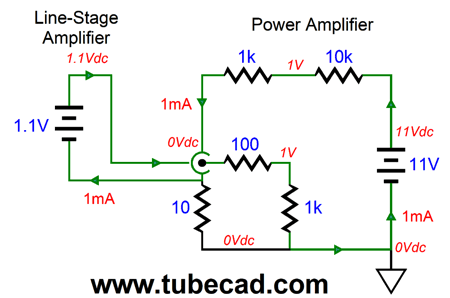
Note how no current flows through the 10-ohm resistor; instead, the current flows through the line-stage amplifier's output, down the interconnect, into the two-resistor voltage divider, up into power amplifier, then through the two negative feedback resistors, entering the RCA jack ground connection, and zipping down the interconnect's ground wire. Okay, I know that having one line-stage amplifier and one power amplifier in the circuit will confuse many, so let's replace them with two batteries.
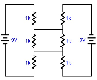
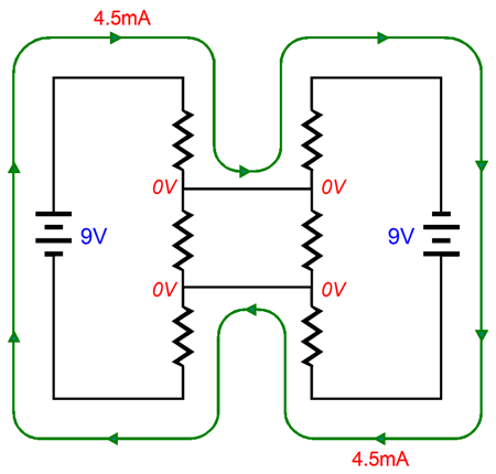
Once again, the 10-ohm resistor is oblivious to the voltages and current flows. Still not seeing it? Okay, lets get really simple and use two 9V batteries and six 1k resistors.
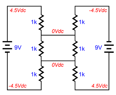
Note the battery polarities. Question: How much current flows through the two middle resistors? Did you guess 3mA or 4.5mA? The correct answer is 0mA. No current flows through these middle resistors. Here is schematic with the voltage filled in.
Note the 0V at both ends of the middle resistors, which means that no current can flow. A proof can be found in removing the two middle resistors and seeing that the same voltage relationships obtain. Here is the actual current path taken.
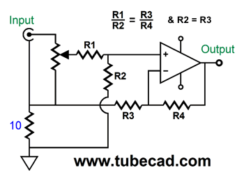
By the way, I am using the conventional viewpoint of current flowing from positive to negative, in contradiction to the actual path taken by electrons. (Old timers get weird when the conventional current viewpoint is criticized.) As I understand it, the US Navy electronic teaching program long ago abandoned conventional current and only uses electron current flow. Does it matter? Mostly no, as most know about the two viewpoints and the history about it. But it is certainly far easier to explain how a triode works if you follow the electrons, as they boil off the cathode and flow up to the plate, instead of them sprinkling down from the plate. So, I must amend my schematic from 2016's post number 357. Resistor R2 and R3 must share the same value. (By the way, while you are at it, check out posts 356 and 355.)
Once again, the problem is that, even when we abide by the formulas, this solution must be implemented by the power amplifier's maker. Now, if I were making solid-state power amplifiers, I would try using two FET-based buffers, so I could sidestep the feedback resistor current problem.
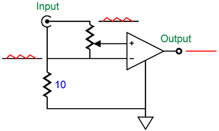
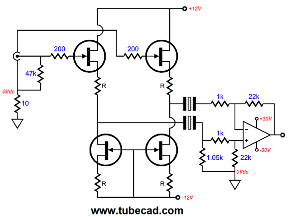
The FET grids, much like a triode's grids, present a staggeringly high input impedance, so the signal source and the 10-ohm to ground do not even know that the FETs are there. The power amplifier is still configured as a differential amplifier, so any common-mode noise will be ignored; in addition, the 10-ohm resistors prevent cross-feeding of ground currents back to the signal source. The funny looking capacitors are non-polarized electrolytic types. (OF course, large valued film capacitors could be used, say at least 10µF.) Another possibility would be to use two gain stages.
Each channel in the solid-state stereo power amplifier holds two gain stages in cascade. The first amplifier runs off of +/-12V regulated power-supply rails, while the second runs off of +/-30Vdc unregulated rails. The first amplifier delivers a gain of 10 (+20dB); the second, 4.3 (+12.7dB). What I like about this two-stage approach is that when the second amplifier clips—and all amplifiers clip—the first doesn't, so it does not have to recover, as it never lost its mind. Moreover, the second amplifier can be configured as a current-feedback type. Once again, these types of solutions must be implemented by the power amplifier's maker. This brings us back to using an output transformer in the line-stage amplifier.
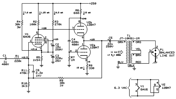
Jensen Tube Circuit
Really? Needlessly complex, isn't it? Where are the essential grid-stopper resistors? Why was resistor R4 included? Why didn't the negative feedback loop extend to the other side of the output coupling capacitor? Sadly, it is easy to make complex and just okay, but simple and effective is difficult. What are our goals? Here is a quick list: low distortion, low output impedance, high PSRR, high input impedance, no negative feedback loop, and big output voltage swings, in spite of the low 600-ohm external load. A good choice would be the SRCFPP topology.
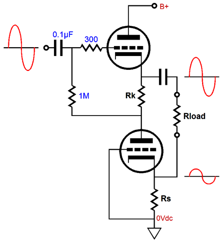
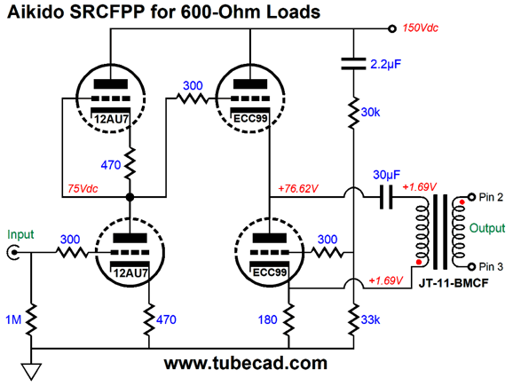
This a push-pull buffer stage that offers the same power output that a White cathode follower would, but also adds the ability to sneak some Aikido mojo into the works through the bottom triode's grid. The following complete design adds just nine resistors and two capacitors to the two tubes and output transformer.
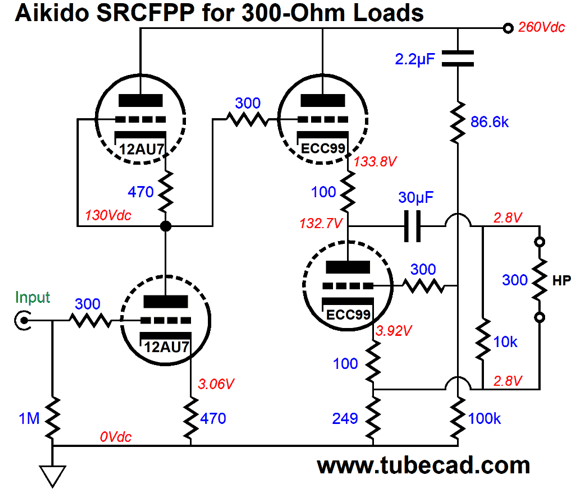
The SRCFPP output stage ensures balanced push-pull operation of the ECC99 triodes. Aikido mojo enters the picture with the addition of the 2.2µF capacitor and two-resistor voltage divider. The 12AU7 provides the signal gain. Notice: No electrolytic capacitors or negative feedback loops were used in the making of this circuit. In addition, the output transformer is a 1:1 type, so we can expect much better performance from over the 11k:600 version used in the Jensen example. Unless you own some pro audio gear, it is unlikely that this circuit's intended load impedance of 600 ohms will be of much use. But then again, some headphones present 600-ohm loads. On the other hand, 300-ohm headphones are more common.
In fact, if we are willing to balanced connectors, we can dispense with the output transformer and make small OTL headphone amplifier.
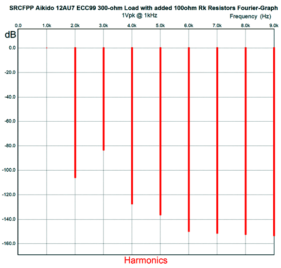
Like the SRPP and White cathode follower, the SRCFPP topology must be configured and optimized for the load impedance. This is achieved by carefully selecting the current-sense resistor value. In the White cathode follower this resistor is the plate resistor; in the SRPP, the resistor between the bottom plate and the top cathode; and in the SRCFPP, the cathode resistor, which in this example is the 249-ohm resistor. So why are the two 100-ohm cathode resistors there? I wanted to limit the idle current to a lower value and I sought some distortion reduction, although I had to pay by giving up some damping factor, as the output impedance must be higher due to their inclusion. Without the added cathode resistors, the idle current goes up from 11mA to about 15mA and the output impedance goes down from about 200 ohms to 100 ohms. I ran some SPICE simulation with the added cathode resistor and the distortion came in at about 0.01% with 1Vpk at 1kHz with the 300 ohm load and it puts out at least 6Vpk before leaving class-A operation. The balance was excellent, which becomes obvious from examining the following Fourier graph. Note the 2nd harmonic.
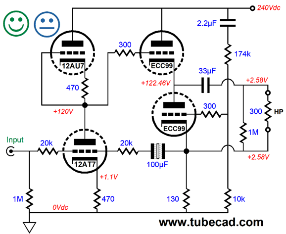
Basically, the greater the reduction in 2nd harmonic, the better the balance between output tubes. As I cannot leave well enough alone, I wondered what else could be doe to this circuit. How about converting it into something closer to a current-out amplifier? The following variation uses an inverting negative feedback arrangement to increase the output impedance to over 700 ohms.
Why? It may sound better to some. Why not everyone? Everyone has his own preference. I remember passing a room at a stereo show that had just ended its lock-door demonstration of of some loudspeakers. Audiophiles poured out of the room with two polar opposite opinions: half bemoaned the travesty they had to endure, while the other half rejoiced in hearing the best sound of their lives. Who was right? Everyone was. Some men prefer blonde woman; others, brunettes; others still, men.
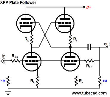
Here is the situation I find myself in. Ever since I posted my XPP circuit, I have gotten super enthusiastic emails that extolled the circuit's sonic signature. At the same time, I am sure that many built the circuit and did not find it to their liking, but didn't email me. I am inclined to believe that something similar will happen with the circuit above: some will love it, others won't. Returning to the problem of keeping each channel's audio signal confined to itself, we face the house-ground problem.
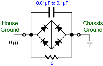
More Potential Problems One workaround is to use a House-Gnd circuit with both audio devices.
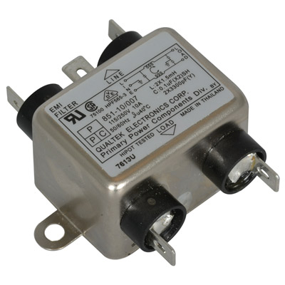
The DC connection is made to the house ground through 10-ohm resistor and the ultra-high-frequency AC connection is made through the small ceramic capacitor. If a fault does occur and the AC live voltage connects to the chassis, two rectifiers will engage and limit the chassis voltage to about 1.4Vdc and the house fuse will blow. Doesn't the 10-ohm resistor still cause grounding problems? If the interconnect ground wire offers only a few milliohms of resistance, we should be okay, as the two 10-ohm resistors will present thousands of times more resistance. While on the topic of wall-socket problems, I should mention a paradox. You add an RFI (Radio Frequency Interference) filter to your system and it can either makes things much better or much worse or do nothing. What is going on here? First, let's make sure we all know what sort of RFI filter I am talking about.
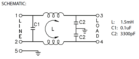
The filter shown above is meant to be situated within the chassis. Similar filters are built into the power cord receptacle. Inside, we often find a circuit like the one shown below, although some are far more complex.
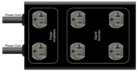
The capacitors and mutual inductor help filter away high-frequency noise. I have added these types of filters to some of my high-voltage power supplies with excellent results. (I once lived near a radio transmitter and I could hear the broadcast on my wall phone and phono preamp and see the visual distortion on my TV screen. The best solution was to move.) At the same time, many have told me that adding these filters "killed" their power amplifier performance or made their system sound brittle. I can see where the filter might limit the big power amplifier's ability to quickly charge its power supply capacitors. And the filter might actually make high-frequency problems worse, if the high-frequency problem originated in the audio device. In other words, what if the wall voltage was clean, but the CD player or the line-stage amplifier's power supply created high-frequency hash that would normally be shunted away into the wall socket, but is now trapped from exiting by the filter. (Although the two capacitors on the right side of the mutual inductor should pass on this hash to the house ground.) Actually, this problem is more likely when many audio devices share a single filter, say one in a AC strip. Here is my proposed workaround.
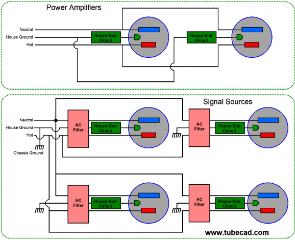
Two power cords leave the terminal strip box, one for powering the power amplifiers and one for all the signal source devices. Here is the schematic.
Note that all the sockets get a House-Gnd circuit, but only the signal source side attaches its house-ground connections to the enclosure. In addition, each signal-source socket gets its own RFI filter, which will help prevent back-feed from one device to the other. I like this setup, as we could add two on-off switches: one for the power amplifiers and one for the signal sources. At start-up, we would first engage the signal sources, then the power amplifiers. At turn-off, the opposite sequence. While on the topic of high-frequency filters, we could add an isolation transformer, but with a twist.
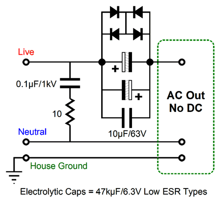
Big toroid transformers are sold with four identical winding, which allows us to either step 115Vac to 230Va or step down 230Vac to 115Vac or to isolate 115Vac to 115Vac. If we add a capacitor and use this arrangement, then only one primary will perform the power transference to the secondary winding. What does the other primary winding do? It only engages in the presence of high-frequencies, as the capacitor only passes those frequencies. Since the primary winding are wired up in anti-phase, the high-frequencies cannot pass, as they buck each other through the two primary windings. I believe that this scheme was created by Menno van der Veen. One last problem we might encounter is DC on the wall voltage. This can be a big deal, as many transformers cannot sustain a prolonged DC current flow. (Older I & E trans were so sloppy in their magnetic structure that an implicit air-gap exists, which protects the transformer core from saturation.) I believe that this might explain why the same amplifier might sound glorious at your house, but not at your friend's house. The workaround is to AC couple the wall's AC voltage through some capacitors.
Note the high capacitance and low voltage rating for the capacitors. As long as the residual DC is not more than about 1.4V, the diodes do not engage and the capacitors block the DC current flow. The 10-ohm resistor and 0.1F capacitor are there to convert RFI into heat. Remember that energy cannot be destroyed, only transformed.
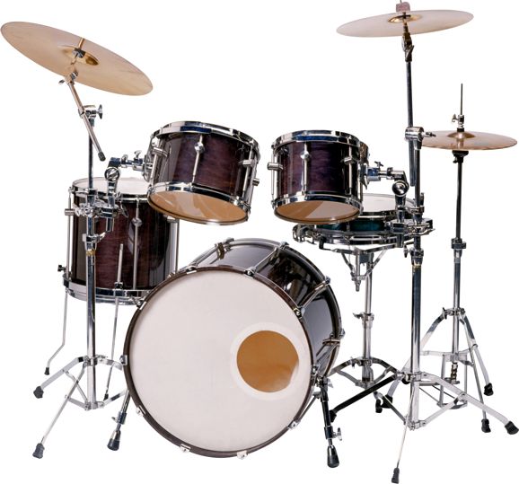
Music Recommendations, Drum Music
I like to hunt through the genres of music that Tidal offers. While searching through new jazz albums, I was struck by how many drum-centric albums appeared in the first ten selections.
Retrograde is a jazz album that would sound quite avant-garde, if it didn't sound so old fashion, something like what John Coltrane or Ornette Coleman might have produced in their more out-there moments over half a century ago. Nonetheless, the drums really do come across with vitality and presence. Try the second track, Abyss Before Zero, to give your system a workout.
Mark Kavuma's new album, Kavuma, first track begins with a drum roll. His entire album was worth hearing.
Jamie Saft's album, Blue Dream, offers some fine drum and bass playing. The 2nd, 5th, and 9th tracks open with drums. This is another enjoyable album, which I will add to my playing list.
Lou Harrison's 2003 album, Drums Along The Pacific, isn't new and isn't jazz, but it is drum centric and Tidal does offer it. Give the second track, Simfony #13, a listen. //JRB
User Guides for GlassWare Software
For those of you who still have old computers running Windows XP (32-bit) or any other Windows 32-bit OS, I have setup the download availability of my old old standards: Tube CAD, SE Amp CAD, and Audio Gadgets. The downloads are at the GlassWare-Yahoo store and the price is only $9.95 for each program. http://glass-ware.stores.yahoo.net/adsoffromgla.html So many have asked that I had to do it. WARNING: THESE THREE PROGRAMS WILL NOT RUN UNDER VISTA 64-Bit or WINDOWS 7 & 8 or any other 64-bit OS. I do plan on remaking all of these programs into 64-bit versions, but it will be a huge ordeal, as programming requires vast chunks of noise-free time, something very rare with children running about. Ideally, I would love to come out with versions that run on iPads and Android-OS tablets.
//JRB
|
|
John Gives
Special Thanks to the Special 66
I am truly stunned and appreciative of their support. In addition I want to thank
All of your support makes a big difference. I would love to arrive at the point where creating my posts was my top priority of the day, not something that I have to steal time from other obligations to do. The more support I get, the higher up these posts move up in deserving attention. Only those who have produced a technical white paper or written an article on electronics know just how much time and effort is required to produce one of my posts, as novel circuits must be created, SPICE simulations must be run, schematics must be drawn, and thousands of words must be written. If you have been reading my posts, you know that my lifetime goal is reaching post 1,000. I have 566 more to go. My second goal is to gather 1,000 patrons. I have 934 patrons to go. Help me get there.
Only $12.95 TCJ My-Stock DB
Version 2 Improvements *User definable Download for www.glass-ware.com |
||


| www.tubecad.com Copyright © 1999-2018 GlassWare All Rights Reserved |