| John Broskie's Guide to Tube Circuit Analysis & Design |
|
26 September 2018 Post 440
Balanced Systems
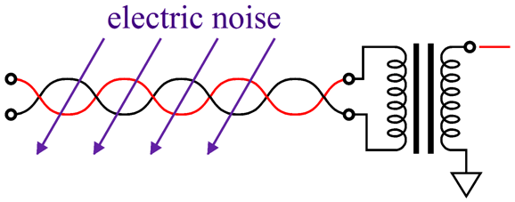
We live in an amazingly noisy electrical world. The sun spits out radio frequency interference, as does lightning. Computer power supplies, light dimmers, car ignition systems, vacuum cleaners, industrial equipment, neon signs, cell phones, and a few hundred thousand other electrical devices all add to electrical circuitry being dirtied by electromagnetic induction and electrostatic coupling. In my house alone, over 20 WiFi and Bluetooth enabled devices are found.
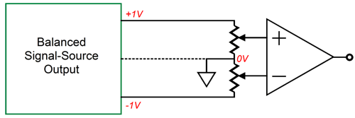
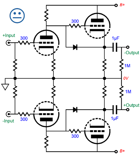
Balanced audio sidesteps much of this electrical pollution due to its common-mode signal rejection, whereby a signal common to both phases, such as extraneous electrical noise, gets rejected. On the other hand, a balanced system that fails to provide common-mode signal rejection is not delivering the true potential of a true balanced system. For example, the following circuit accepts a balanced pair of input signals, and it puts out two output signal in opposite phase, but does not deliver any common-mode signal rejection.
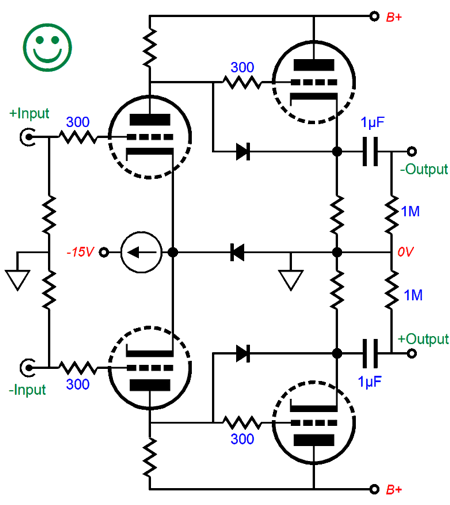
If the same input signal is presented to both grids, both triodes will amplify the shared signal. In contrast, the following balanced circuit will largely reject the common-mode signal.
The constant-current source and the bridging of the two cathodes made all the difference. A common-mode signal becomes invisible to the two grids, as the bridged cathodes simply follow the common-mode signal and the triodes maintain a constant-current draw, so no change in plate voltage occurs, so in turn no output signal is developed. By adding an input 1:1 transformer to the defective balanced circuit, however, the circuit is transformed in to a fully balanced circuit, as the input transformer's intrinsic common-mode signal rejection saves the day.
The problem with input signal transformers is their high cost and limited frequency bandwidth. While the high cost is truly regrettable to most, it could be viewed as feature hardcore audiophiles; moreover, the truncated frequency bandwidth can actually prove a feature, as subsonic and ultrasonic signals can cause audio-system headaches. For example, warped LPs and RFI only subtract from the musical content. Moreover, a good input transformer can solve problems, such as ground loops and house-ground loops, better than any other approach. I must admit that I used to be profoundly anti signal transformer, but I have made a complete reevaluation of their merits and disadvantages. I now firmly believe that a good signal transformer can be a blessing. My first experiences with signal transformers were poor due to my experimenting with poor signal transformers that I had pulled from old clunker electronic gear. These were cheaply made transformers with dismal core material and no shielding. In contrast, the fine signal transformers made by Altec, Cinemag, Jensen, Lundahl, Tango, and others. Although expensive, deliver excellent performance. One potential problem we face with signal and tube-based gear is the relatively high impedances and resistances in tube circuits. Unlike capacitors, which thrive in high-impedances applications, transformers work best with low impedances. The 600-ohm termination standard in professional audio was imposed to allow signal to work better. Ideally, a tenfold or hundredfold decrease in impedance would make it far easier to use signal transformers. Think about it: in a large auditorium, filled with a thousand lights, lights that do no simply turn on and off, but are slowly brought to life with power dimmers; and filled motorized curtains and miles of electric cabling, the lower the termination impedance, the less electrical interference can seep into the desired signal. With solid-state gear, low impedances are easy to realize, but not so with tube gear. For example, a 12AX7-based cathode follower will struggle to drive a 10k potentiometer. In other words, we need to ensure that our tube-based gear is up to the task of driving the signal transformer. Many will argue that we needn't brother, as balanced, low-impedance-terminated gear only makes sense in a professional-audio application, not in a home. I used to believe this as well. I no longer do, as our homes are no longer as electrically-noise-free as they once were. Here is an example that I am sure I have mentioned before: I was at a buddy's house, listening to his excellent stereo system, when I heard a buzzing sound sully the sonic glory. I had heard a similar buzz before and I asked him if his wife was home. She was. I then asked to see if she had turned on a light dimmer partially. She had. He turned it off and the buzz was gone. A month later, we are listening away again and the same buzz entered the sound. His wife wasn't home. He looked out his window and pointed to the house next door, explaining to me that his neighbors light dimmers also pollute his system. I assume that they both shared the same power company transformer on the telephone pole. Perhaps some fancy line conditioner would have solved the problem, but I bet a completely balanced system could have sidestepped the buzz.
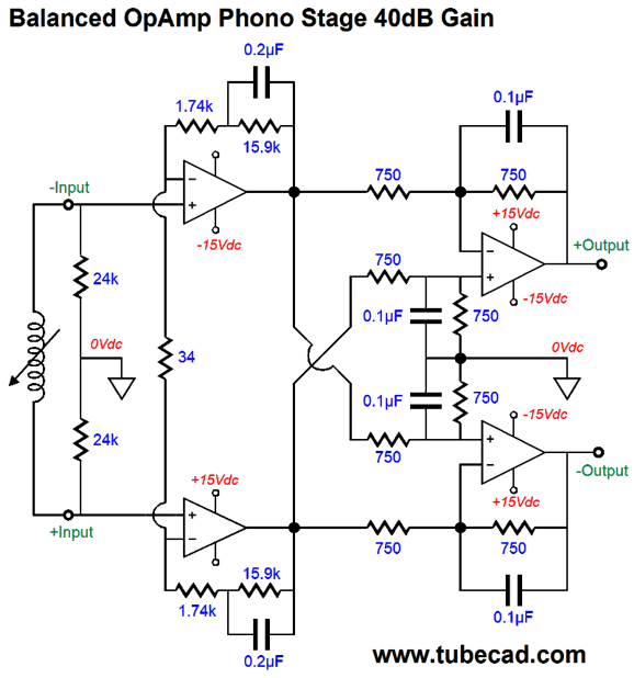
Balanced Phono Preamps One design that came to mind was the following, which uses two stages.
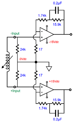
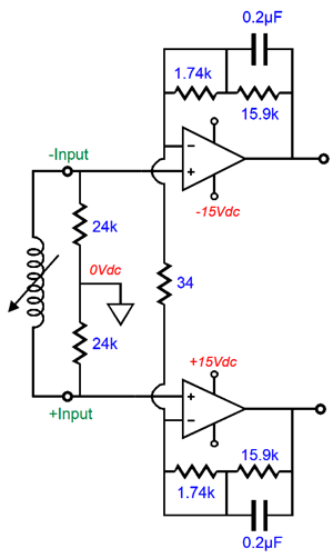
The two input OpAmps provide all the gain and establish the 50Hz to 550Hz RIAA equalization. The problem with this topology is that its common-mode-rejection ratio (CMRR) is equal to its gain. Still, this is a huge improvement over the following variation, which offers no CMRR.
Note how two resistors are used and how their nexus goes to ground. In contrast, the single-resistor version puts out the common-mode signals at unity gain.
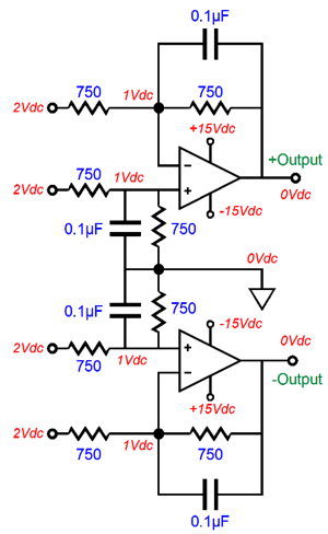
They way we achieve a higher CCMR is with the second stage, which consist of two differential unity-gain amplifiers.
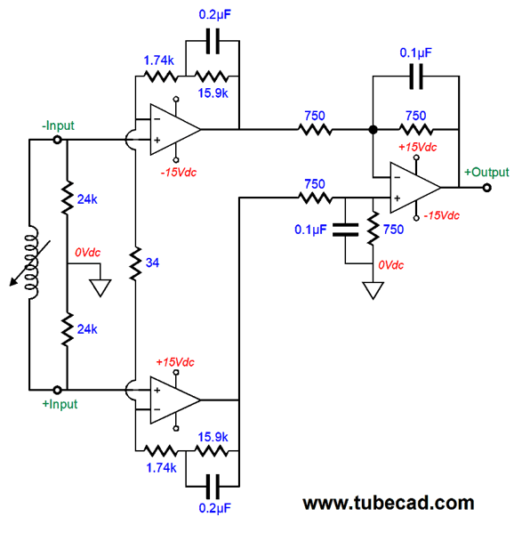
As long as tightly matched resistors are used throughout, we can achieve a high CMMR. In addition, these differential amplifiers set the 2122Hz RIAA equalization by encompassing a low-pass filter on the balanced input signals. If we want an unbalanced output signal, we can simply use a single OpAmp in the second stage.
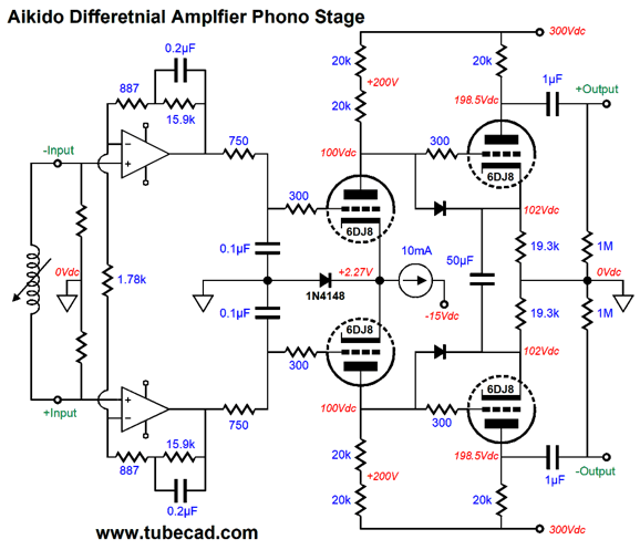
Okay, let's now move on to a hybrid balanced phono stage. The design uses the input stage from the previous solid-state design and uses a passive RC filter to realize the 2122Hz (75µS) RIAA equalization.
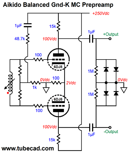
The constant-current source that loads the the two joined cathodes grants the triode-based differential amplifier its stellar CMRR. In other words, the OpAmp portion only gets partially there, while the differential tube stage furthers the CMRR.
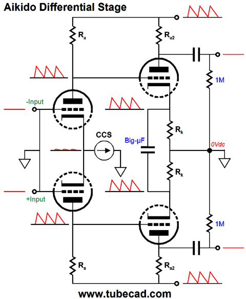
The "Aikido" aspect of this circuit is found in the last stage, which undoes the first tube differential's extremely poor PSRR, i.e. next to none. See post 431 for more details on the Aikido differential amplifier. By the way, Note that no negative power-supply rail was used in the circuit shown above. This might prove a problem with the solid-state constant-current source, as it might become voltage starved. If you are using a step-up transformer, the following workaround gives the grids a small positive voltage to increase the cathode voltage, giving the constant-current source more voltage to work within.
By the way, be sure check out post 327 for this interesting variation that does not use a constant-current source.
No step transformer is used in this example—but it could be. Adding an input transformer will add common-mode signal rejection.
Going Horizontal
How well does this circuit work? Extremely well, in terms of THD. Here is the SPICE-generated Fourier graph.
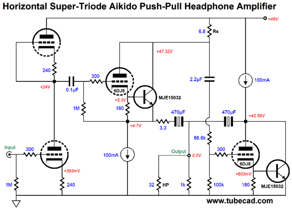
This represents less than 0.1% THD. The one problem with this circuit, much like the standard White cathode follower, is relatively poor PSRR. We can overcome this failing by making an Aikido push-pull amplifier.
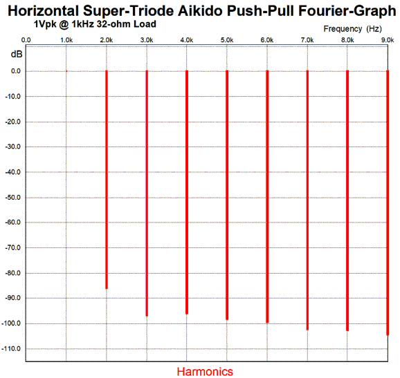
Note the 2.2µF capacitor and the two-resistor voltage divider that feeds the rightmost triode's grid. The input stage leaks 50% of the power-supply noise at its output, so we feed a portion of this noise slightly greater than 50% to the rightmost triode's grid, which will force a ripple null at the output. Here is its Fourier graph.
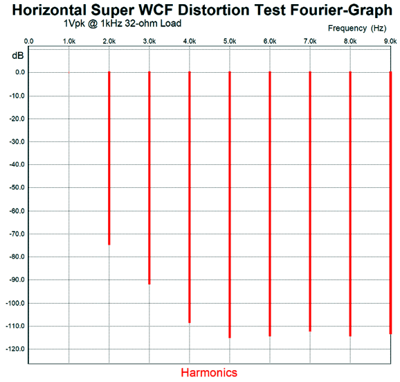
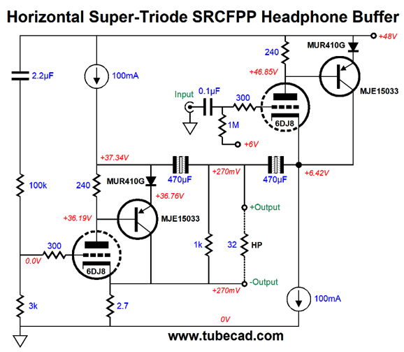
The 2nd and 3rd harmonics are lower with the input stage in place, but all the other harmonics are higher. Interesting. Do not forget that this circuit is not just a buffer, but a gain stage. Now, it's time to go horizontal with the SRCFPP.
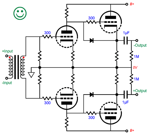
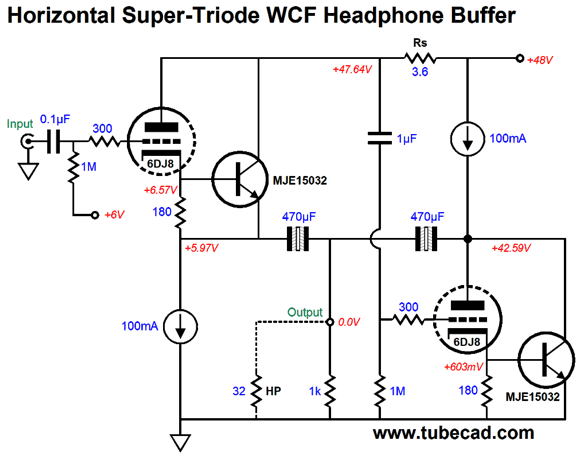
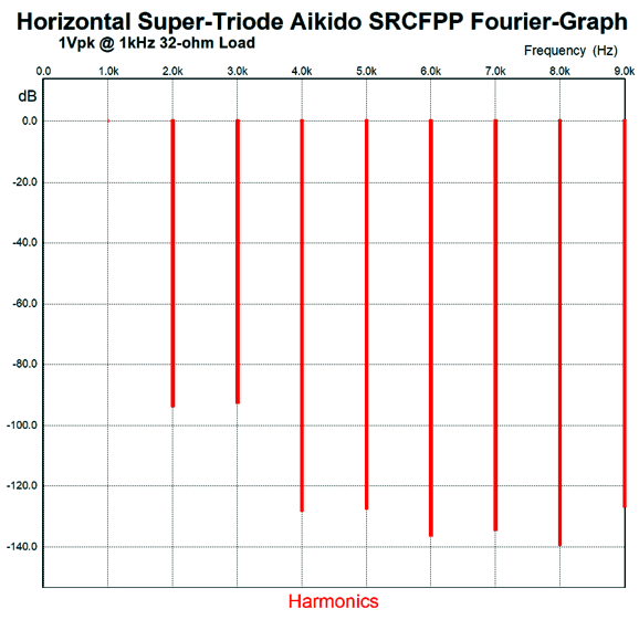
Once again, the constant-current sources allow the horizontal move and save the day. Transistors are tweaky devices due to their screaming transconductance, as an extra 0.1V on the transistor gate makes for a huge increase in current conduction, which is why emitter resistors are so often used. In this circuit, the MUR410G rectifiers offer very little effective series resistance, so they cannot save the day. The constant-current sources, on the other hand, set strict idle current limit. The THD is wonderful, coming in at below 0.01%.
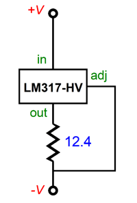
The output impedance was less than 10ohm in SPICE simulations and the PSRR was at least -40dB, if not closer to -60dB. All of these circuits belong to the trinity of lazy push-pull circuits. And all made use of 100mA constant-current sources, which implies a peak output current swing of 200mA, which into a 32-ohm load implies a peak voltage swing of 6.4Vpk, a peak voltage we are not likely to actually realize, as the constant-current sources only allow for about a 3Vpk swing before they are voltage starved. Speaking of the constant-current sources, the simplest way to implement would be to use an LM317-HV, which is good for up to 57V of voltage differential.
The 12.4-ohm resistor sets an idle current flow of 100mA. If a plain LM317 is used, we should place a 30V zener in parallel with the constant-current sources.
Music Recommendation:Duets by Kevin Eubanks, Stanley Jordan Well, when I heard Kevin Eubanks and Stanley Jordan guitar duet of Summertime, I had to hear the rest their Album, Duets. Not only is the music intensely satisfying, the recording is exemplary. Highly recommended. With Tidal, you must search for "Kevin Eubanks," not "Stanley Jordan," as Tidal does not list this album in Jordan's list of albums. //JRB
User Guides for GlassWare Software
For those of you who still have old computers running Windows XP (32-bit) or any other Windows 32-bit OS, I have setup the download availability of my old old standards: Tube CAD, SE Amp CAD, and Audio Gadgets. The downloads are at the GlassWare-Yahoo store and the price is only $9.95 for each program. http://glass-ware.stores.yahoo.net/adsoffromgla.html So many have asked that I had to do it. WARNING: THESE THREE PROGRAMS WILL NOT RUN UNDER VISTA 64-Bit or WINDOWS 7 & 8 or any other 64-bit OS. I do plan on remaking all of these programs into 64-bit versions, but it will be a huge ordeal, as programming requires vast chunks of noise-free time, something very rare with children running about. Ideally, I would love to come out with versions that run on iPads and Android-OS tablets.
//JRB
|
|
John Gives
Special Thanks to the Special 66
I am truly stunned and appreciative of their support. In addition I want to thank
All of your support makes a big difference. I would love to arrive at the point where creating my posts was my top priority of the day, not something that I have to steal time from other obligations to do. The more support I get, the higher up these posts move up in deserving attention. Only those who have produced a technical white paper or written an article on electronics know just how much time and effort is required to produce one of my posts, as novel circuits must be created, SPICE simulations must be run, schematics must be drawn, and thousands of words must be written. If you have been reading my posts, you know that my lifetime goal is reaching post 1,000. I have 560 more to go. My second goal is to gather 1,000 patrons. I have 934 patrons to go. Help me get there.
Only $12.95 TCJ My-Stock DB
Version 2 Improvements *User definable Download for www.glass-ware.com |
||


| www.tubecad.com Copyright © 1999-2018 GlassWare All Rights Reserved |