| John Broskie's Guide to Tube Circuit Analysis & Design |
|
14 November 2018 Post 446
Two-Amplifier Cascade
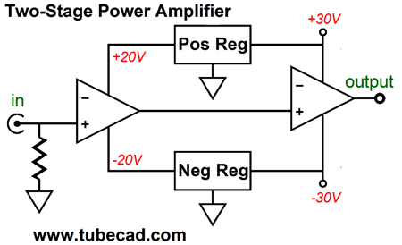
Well, I am convinced that the two-amplifier cascade performs better in actual use. Moreover, with two cascading amplifiers, each can be optimized for its intended task. The input amplifier never sees a 4-ohm to 16-ohm load or long lengths of loudspeaker cable; instead, it sees a fixed load impedance, probably in the tens of thousand ohms. The output amplifier no longer has to deliver all the signal gain and it can be optimized for big voltage and heavy current delivery. In fact, we might be able to get away with only two stages within the output amplifier, rather than the typical three stages (input, VAS, and output stage). How we should distribute the ratio of gain between amplifiers is an interesting question. If we desire equal gain from each amplifier, both amplifiers need only deliver a gain equal to the square-root of the total desired gain. For example, if we need a final gain of 25, each amplifier should put out a gain of 5. Of course, we can alter the ratio, say a gain of 10 from the input amplifier and a gain of 2.5 from the second amplifier. Hell, we could get a gain of 25 from the input amplifier and unity gain from the output amplifier. With this last arrangement, however, both amplifiers would at least need to run off the same power-supply rail voltages; although a case could be made for running the input amplifier on higher rail voltages, if the output amplifier held enhancement-mode MOSFETs in the output stage, for example. On the other hand, if the input amplifier delivers a gain of 5, this amplifier could run off far lower power-supply rail voltages, as only +/-5Vpk voltage swings would be needed from its output, say bipolar rail voltages of only +/-8Vdc. In addition, lower power-supply rail voltages for the input amplifier allow us to use voltage regulators that run off the higher power-supply rails that feed the output amplifier.
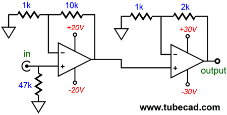
I must argue for higher rail voltage for the input amplifier, as I never want the input amplifier to clip. For example, if the input amplifier offers a gain of 5, I would use +/-20Vdc power-supply rail voltages, in spite of the tiny +/-5Vpk output voltage swings. When I said never clips, I meant it. I fully expect the output amplifier to clip, which will only cause problems local to that output amplifier. In contrast, when a typical solid-state single power amplifier clips, problems arise throughout the amplifier, not just the output stage. When the output amplifier recovers from its clipping, it will still see a large clean input signal.
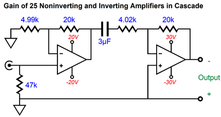
One hidden advantage to the two power amplifier in cascade arrangement is that both amplifiers can be inverting types, which results in no phase inversion at the loudspeaker, as the two inversion cancel. Mind you, phase inversion is not an insurmountable problem, as we only need to flip the connections at the loudspeaker terminals. But creating a single, high-power inverting amplifier is tough, as the high power implies high gain and high gain implies a big ratio between negative feedback resistors values, which in turn implies a lower-valued input resistor and higher-valued feedback resistor than we would like. For example, say we desire an input resistance of 100k. Well, the negative feedback resistor would then have to be 2.5M to get a gain of 25. (By the way, 25Vpk into 8-ohms equals 39W; 200W, on the other hand, requires a peak voltage swing of 56.6Vpk.) The problem is that 2.5M is crazy big, so much so that any stray capacitance will kill the high-frequency response. In addition, many solid-state power amplifier become squirrelly with a negative feedback resistor value above 30k. But with two inverting amplifiers in cascade, the feedback resistor ratio falls dramatically. For example, with a gain of 5 each, the input amplifier can use the 100k input resistor value and a 499k negative feedback resistor value, while the second power amplifier can use 1k and 4.99k values. (This becomes a bigger feature if a current-feedback topology is used in the output amplifier.)
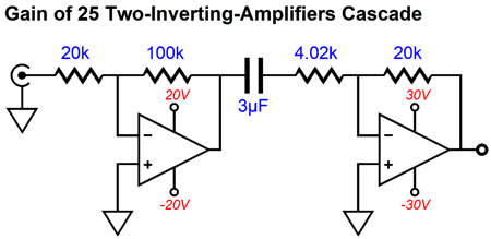
Note the single coupling capacitor, which is a film or PIO type, not an electrolytic type. Even if the input amplifier exhibits a large DC offset, either due to the input signal containing DC voltage component or due to the amplifier itself giving rise to the DC offset, the coupling capacitor blocks the Dc voltage. The output amplifier uses all its considerable open-loop gain at low frequencies to eliminate the DC offset at its output, as the coupling capacitor prevents any two-resistor voltage division from occurring. By the way, we can get away with a single coupling capacitor with a cascade of non-inverting to inverting.
Note that both amplifiers deliver a gain of 5. Also note the need to flip the loudspeaker cable phase, as the OpAmp signal inverts the input signal's phase. Another possible, but secret, advantage to the two-amplifier cascade is that we can turn off the OpAmp amplifier and use the input amplifier as a headphone amplifier, as a gain of 5 is probably ideal for this application. If 16-ohm headphones must be driven, the input amplifier can drive a unity-gain buffer stage. I may be alone in this, but the dual use seems a fun feature. Surely, you are not going to listen to both headphones and loudspeakers at the same time. (I used to run my subwoofers while listening to headphones. The sub crossover was a low 80Hz, which prevented my neighbors from localizing the source of the bumping thuds. My running gag was to let friends listen to the headphones and subs, but not tell them about the subs. As soon as I detected the move to remove the headphones, I would mute the sound. Invariably, the listener would exclaim, "Damn, that's the best bass I have ever heard from a headphone; it made my whole body shake.")
Tubes Enter the Picture
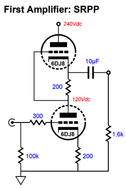
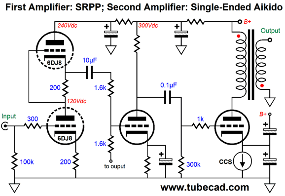
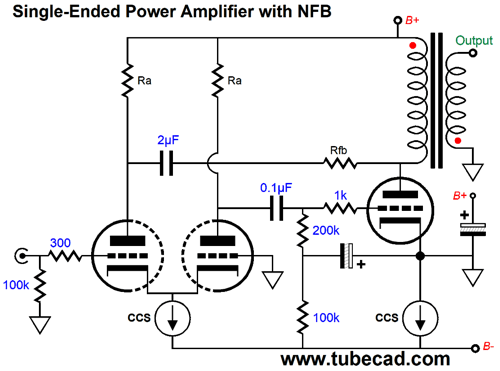
The output amplifier's inverting negative feedback results in an input impedance roughly equal to the 1.6k resistor value, which is low enough to warrant the SRPP circuit as the input amplifier. The 6DJ8 and cathode resistor values were picked to ensure balanced push-pull operation into this low input impedance. By the way, in the absence of SPICE, we can resort to math and a hand calculator. The formula for the optimal resistor value for the top cathode resistor (Rak) is Rak = (rp + 2Rload) / mu If we solve for Rload, the load impedance, we get: Rload = (muRak - rp) / 2 Where mu is the triode's amplification factor; rp, the triode's plate resistance; and Rload, the load impedance.
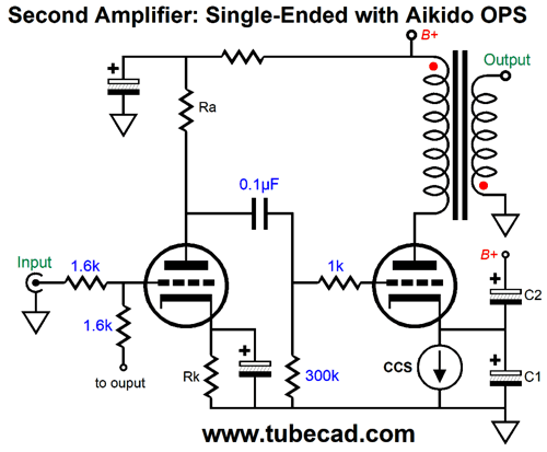
Now, the second amplifier holds a single-ended output stage that embodies some Aikido mojo, as the two capacitors that attach to the cathode inject just enough power-supply noise to create a power-supply noise null across the output transformer primary, which in turn results in an enhanced PSRR at the loudspeaker. The single triode input stage is a simple grounded-cathode amplifier with a bypass cathode resistor. The two 1.6k resistors define an inverting negative feedback loop that results a near unity-gain output. With the 1.6k load impedance, the 6DJ8-based SRPP stage realizes a gain of 8, so the total gain will come in at nearly 8. A peak voltage swing of 8V across an 8-ohm load equals 4W of power. Why so little power? The single triode output tube. If we use a more powerful output triode or several in parallel or a beefy pentode, we could get easily twice the peak voltage swing and four times as much output wattage (16W). In this case, we would replace the 1.6k that attaches to the output with a 3.2k negative feedback resistor.
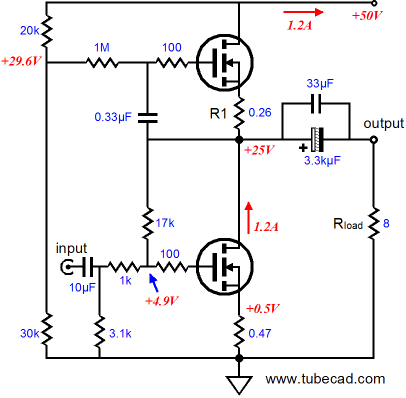
Another amplifier with similarly low input impedance is the Zen single-ended power amplifier. Due to the power MOSFET's high input capacitance, low-resistance negative feedback resistors must be used, if we wish to maintain high-frequency bandwidth.
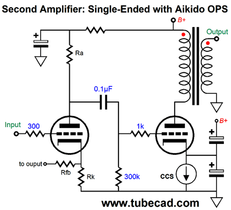
On the other hand, if we use a single-ended input amplifier, rather than the push-pull SRPP, we get a much higher gain. For example, a 6DJ8-based Aikido stage will deliver a gain of 16. Since this first amplifier gives us all the gain we need, we can use the following high-input-impedance second amplifier.
Note that the input triode's cathode resistor terminates into the amplifier output. In other words, the output transformer's secondary provides a current path to ground for the input triode. I know it looks a bit confusing, but this setup is not that different from the typical setup, like the following.
Negative feedback resistor Rfb forms a two-resistor voltage divider with the cathode resistor and limits the amount of output signal delivered to the input triode's cathode, which results in higher gain. But with the single cathode resistor terminating into the output, 100% of the output signal is returned to the input triode, resulting in unity gain at the output. In other words, we are using all the negative feedback we can. By the way, the Aikido output stage could be replaced by a pentode output stage.
The pentode, unlike the triode, presents a truly high plate impedance, so in a single-ended output stage it exhibits a naturally good PSRR, but far worse output impedance and higher distortion, both of which the negative feedback will work to undo.
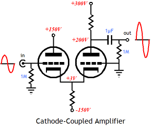
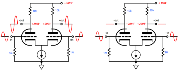
Cathode-Coupled Input Stages
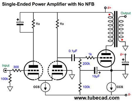
No negative feedback loop is employed; instead, we just rely on the triode's intrinsically low distortion and low output impedance. Ground is wherever the output tube's cathode voltage falls. In other words, the power supply is floating, as it makes no direct connection to ground. This means that each channel must get its own independent floating power supply. This also means that the B+ voltage effectively becomes the center of this amplifier's universe; in other words, the amplifier is B+ referenced. This explains why the output tube's bypass capacitor terminates into the B+ voltage and why the left plate resistor (Ra) is bypassed to the B+ voltage and not ground; it also reveals why the 100µF capacitor is needed, as it shields the cathode-coupled amplifier and output tube from the all the noise that resides below the two constant-current sources. Think of it as the thinking-man's Ultra-Path. If we want to add a negative feedback loop, we can. We can use the cathode-coupled amplifier's second grid, but we will have to flip the output transformer's secondary, as we need the phase inversion. If we fail to get the phasing right, we will end up with positive feedback and wild oscillations.
Alternatively, we can apply negative feedback at the cathode-coupled amplifier's left plate.
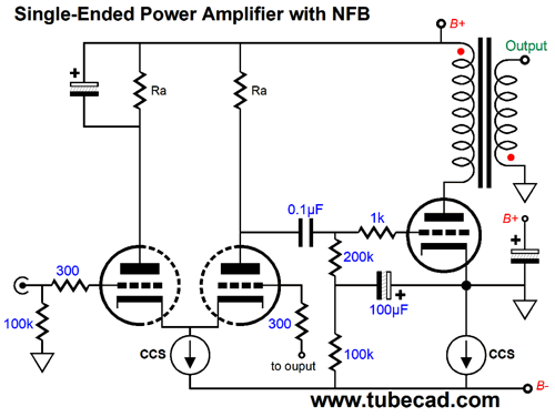
The big problem with negative feedback and transformer-coupled output stages is that the transformer is an electrically messy device. It is a vastly complex device, filled with primary and secondary DCR, leakage inductance, multiple capacitances, and non-linear core material. The amazing thing is that so many transformer-coupled tube amplifier do sound good. So, if we can keep the negative feedback loop on the primary side of the output transformer, our odds go up for having an easy time of it.
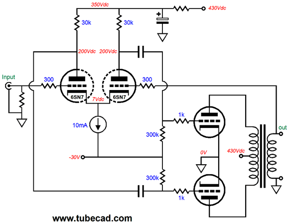
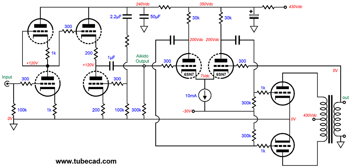
Push-pull Second Amplifier
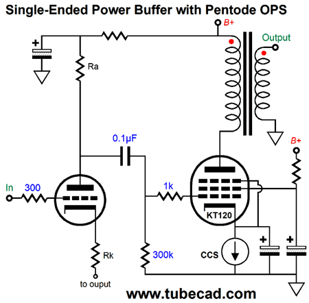
As configured, this is a simple push-pull power amplifier with a negative feedback loop. Normally, a single 6SN7 would prove insufficient to the task of driving the push-pull output stage, as too little gain could be realized. But in a two-amplifier cascade, the input amplifier greatly unloads the second amplifier from having to deliver lots of gain. For example, 1Vpk of input signal would enter the input amplifier and come out as 20Vpk, which if delivered to an 8-ohm load would yield 25W of power. In other words, the output amplifier may not need to develop any gain at all. In which case, we can build a unity-gain power buffer for the output amplifier.
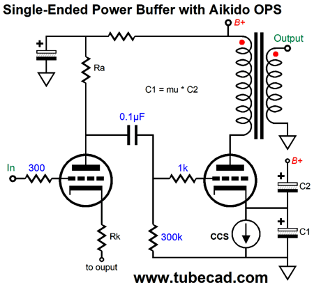
An Aikido gain stage is used as the input amplifier and it is followed by the power buffer. If more gain is needed, we can replace the 12AY7/6072 with a 12SL7 or 12AT7/ECC81 or 5751. If less gain is needed, which is likely, we can use a 6N1P or 6DJ8 or 12AU7. Where things get tricky is where truly high power output is realized, say 56.6Vpk (200W into 8 ohms). With such high output swings, the differential input stage will bottom out, crashing into the negative power-supply rail voltage. The only two workarounds that I can think of are either to use a bigger negative power-supply rail voltage, say -60V, or to let the output amplifier develop some gain, say 3 to 8, and use a lower mu input triode in the Aikido gain stage. We could use power pentodes in the output stage instead of the triodes.
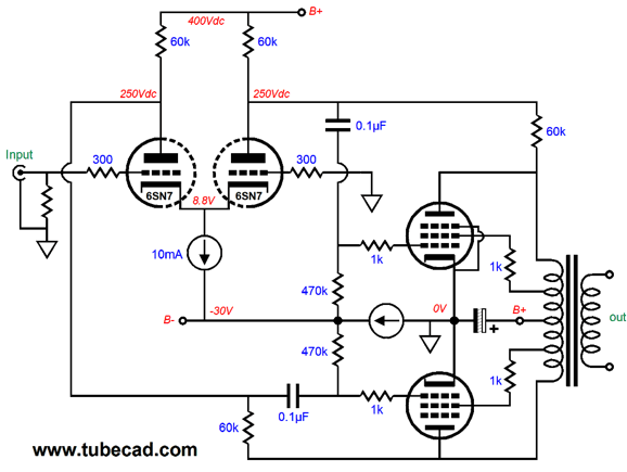
Note how the negative feedback is taken at the primary side of the output transformer, not the secondary. Also note how this amplifier's true signal reference is the B+ connection and how a floating power supply is used. Returning to the triode output stage, here is the entire amplifier.
The second amplifier operates as unity-gain power buffer, so the first amplifier must provide all the gain.
Alta Fedeltà PDF Downloads
Music Recommendation: European Jazz Last time, I recommended Florian Weber's album, Lucent Waters. While searching for other albums by Weber albums at Tidal, I noticed that he had partnered with Markus Stockhausen to produce an album, Alba.
Markus Stockhausen is a German trumpeter and composer; moreover, he is the son of composer Karlheinz Stockhausen. Markus is definitely far less well-known than he should be, as he is one great jazz player.
One of his albums of his that I truly enjoy is Far into the Stars. In addition, the recording is excellent and the album shows off your stereo system extremely well. Both Albums are available at Tidal. //JRB
User Guides for GlassWare Software
For those of you who still have old computers running Windows XP (32-bit) or any other Windows 32-bit OS, I have setup the download availability of my old old standards: Tube CAD, SE Amp CAD, and Audio Gadgets. The downloads are at the GlassWare-Yahoo store and the price is only $9.95 for each program. http://glass-ware.stores.yahoo.net/adsoffromgla.html So many have asked that I had to do it. WARNING: THESE THREE PROGRAMS WILL NOT RUN UNDER VISTA 64-Bit or WINDOWS 7 & 8 or any other 64-bit OS. I do plan on remaking all of these programs into 64-bit versions, but it will be a huge ordeal, as programming requires vast chunks of noise-free time, something very rare with children running about. Ideally, I would love to come out with versions that run on iPads and Android-OS tablets.
//JRB
|
|
John Gives
Special Thanks to the Special 71
I am truly stunned and appreciative of their support. In addition I want to thank
All of your support makes a big difference. I would love to arrive at the point where creating my posts was my top priority of the day, not something that I have to steal time from other obligations to do. The more support I get, the higher up these posts move up in deserving attention. Only those who have produced a technical white paper or written an article on electronics know just how much time and effort is required to produce one of my posts, as novel circuits must be created, SPICE simulations must be run, schematics must be drawn, and thousands of words must be written. If you have been reading my posts, you know that my lifetime goal is reaching post 1,000. I have 554 more to go. My second goal is to gather 1,000 patrons. I have 929 patrons to go. Help me get there.
Only $12.95 TCJ My-Stock DB
Version 2 Improvements *User definable Download for www.glass-ware.com |
||


| www.tubecad.com Copyright © 1999-2018 GlassWare All Rights Reserved |