| John Broskie's Guide to Tube Circuit Analysis & Design |
|
10 December 2018 Post 449
Happy Hanukkah
Happy Hanukkah
Retro Super Class-A
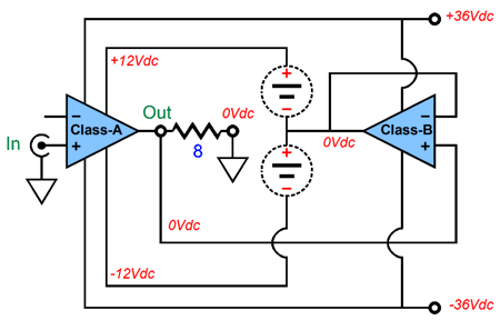
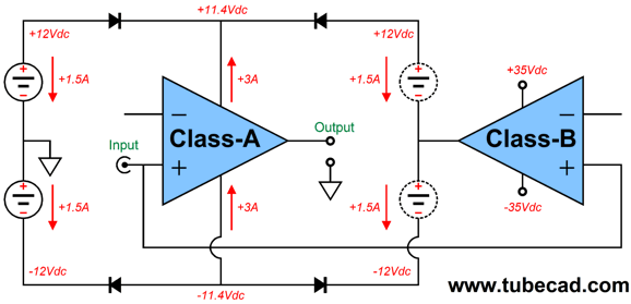
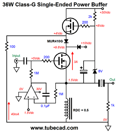
At idle, the class-A amplifier might idle at 3A, while the class-B amplifier idles at only 100mA. The class-B amplifier's input signal is the class-A amplifier's output signal. As speaker sees music signal, the loudspeaker's flow of current gets passed on to the class-B output stage. Here is an example, which uses a DC output voltage of 8V from the class-A amplifier.
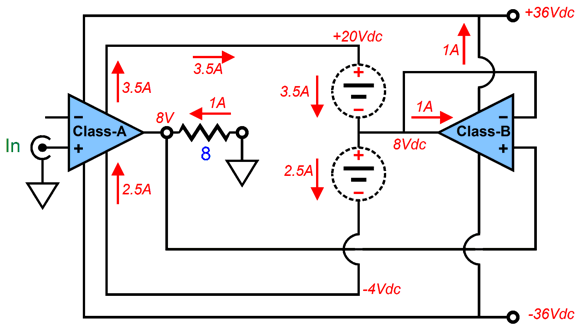
Notice that the bottom half of the class-A amplifier's output stage sees it current flow lessen to 2.5A, while the top half sees its rise to 3.5A. The delta, the difference, , i.e. 1A, between these two is what the speaker sees; and the top half of the class-B amplifier's output stage sees it current flow rise by at least 1A. This amount of current against the 28V voltage drop across the top half of the class-B amplifier's output stage produces 28W of heat dissipation. In other words, although the top half of the class-B amplifier's idle current is low, it must be robust enough to sustain big current swings. Also note that the input and driver stages run off the +/-36V rails. This is essential, as the input signal is referenced to ground, so the input stage's negative power-supply rail must never go positive. Here is an example wherein the entire class-A amplifier sees only the floating power-supply rail voltages:
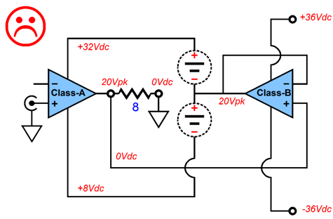
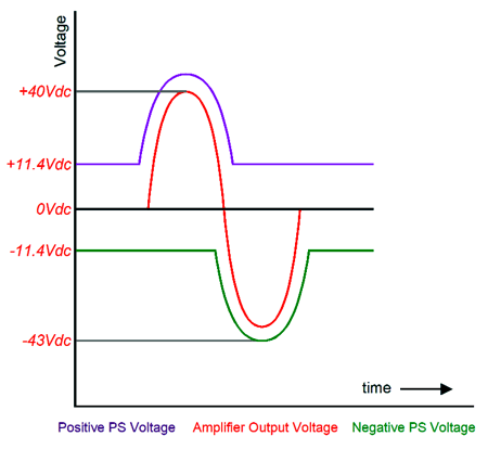
The floating power-supply rails are lifted up 20V, which causes the class-A amplifier's negative power-supply rail to go positive relative the the input signal, which the input stage cannot handle. Now, note how the input and driver stages never see a positive voltage in the following schematic.
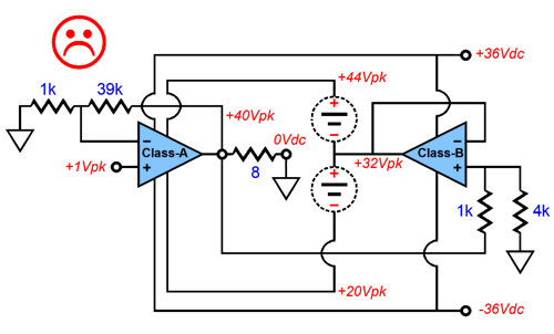
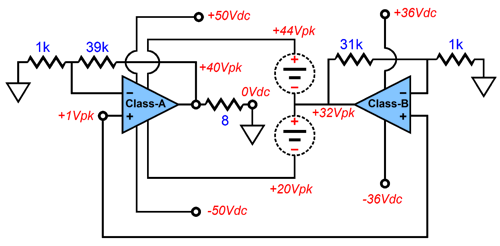
Okay, now let's say that our goal is the extract the maximum output wattage from the super class-A amplifier. With the +/-36Vdc power-supply rails, we assume that the class-B amplifier from the schematic above can swing peak output voltage swings of +/32V. To this 32V of peak voltage we add the floating power supply's +12, making a total positive rail voltage of 44Vpk for the class-A amplifier's output stage. Now, if the class-A amplifier were able to swing peaks of 40V, the power output into an 8-ohm load would be 100W, as 40²/(2Rload) equals 100W. There's a problem, however, as the class-A amplifier's driver stage cannot swing that high, as its positive rail voltage is only 36Vdc.
One workaround would be to give the class-A amplifier's input and driver stages higher rail voltages, say +/-50Vdc.
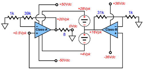
Now, this super class-A amplifier can sustain a peak voltage swing of 40V into the speaker. We have to be careful not to make a workaround that only works at one target voltage. In other words, what happens at lower output voltage swing, say half as much?
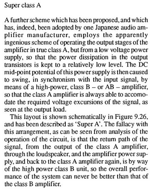
From the schematic above, we can see that all is well, as the class-A amplifier's output stage is not, with +8V of headroom, voltage starved. I should mention that John Linsley Hood, in his book, The Art of Linear Electronics, didn't think much of the super class-A arrangement. Here is what he said:
Page 173 I hate to disagree with one of my heroes, but I am sure that he was wrong here. Perhaps, in terms of frequency response, his argument would prove valid; or if the class-B amplifier exhibited gross phase shift, he would be right. In terms of THD, however, I cannot see how he could be right, as the class-A amplifier's negative feedback loop will work to keep its output in line with its input signal, which it will do as long as the class-A amplifier has sufficient power-supply voltage to accomplish its goal; the class-B amplifier is actually part of its power supply. What about tubes? Couldn't the small class-A amplifier be tube-filled? Perhaps it could, but it would require same fancy fiddling. For example, let's imagine a 10W class-A pentode-based push-pull amplifier with transformer coupling. Okay, now we must use a class-B to bump up the B+ as needed to deliver bigger watts, say 100W. But here is the important part: we never need to bump down the B+ below its idle value.
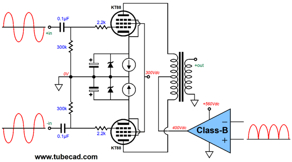
In other words, when the speaker sees a negative voltage swing, the B+ still needs to climb for bigger watts. Of course, an OTL output stage would be entirely different. But with a center-tapped primary on an output transformer entirely different from an OTL. So, what we need to do is to rectify the input signal sent to the class-B amplifier. This also means that the class-B need not be a push-pull type; in fact, a single-ended amplifier will do. One possible arrangement would be to implement a class-G arrangement.
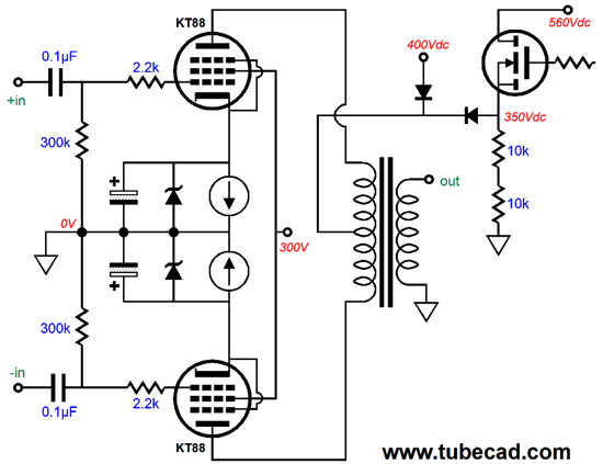
Note that a single N-channel MOSFET is used as the class-B amplifier. Also note that two power-supply rail voltages are used: 400Vdc and 560Vdc. Because the class-G nature of the setup, the MOSFET will get hammered when the MOSFET's source rise a tad above 400V, as the all the current being drawn by the output stage will suddenly flow through the MOSFET. For example, assuming that each constant-current source draws 100mA, the MOSFET will see its 18mA idle current slam up to 200mA. Not shown was the rectifier circuit, nor the driver circuit for the MOSFET. Ready for this? Many NOS tube signal diodes languish unsold, unused, unloved. We could use two of these vacuum tube diodes and the two signals coming off the phase splitter's output to feed a single triode's grid, and whose plate would drive the MOSFET's gate. According to my quick, back of an envelope, calculations revealed, we might go from 25W to 50W, with the right primary impedance. Getting 25W of class-A power from a pair of KT88 or KT120 tubes is easy, but getting 50W would otherwise be impossible. The 300Vdc that feeds the pentode screens should be extremely well-filtered or regulated. By the way, a pentode's screen offers far more control over the pentode's plate in the conduction of current through the pentode. In short, this might be an interesting audio amplifier arrangement.
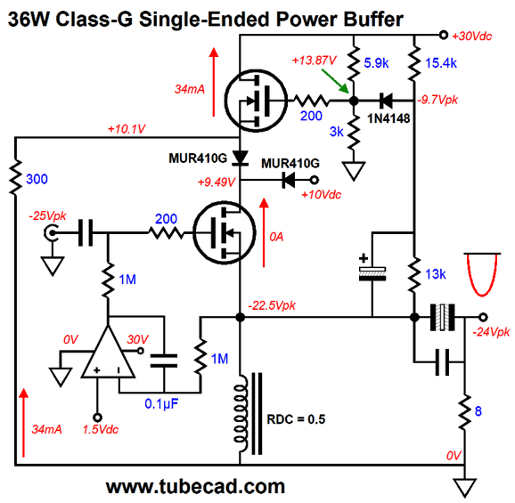
Class-G Super Class-A Amplifier
Since both bipolar power supplies offer the same voltage, both will share equally the current flow into the class-A amplifier. As the class-A amplifier's output signal swing un and down, so too will the class-B amplifier's output, which will expand the rail voltages going to the class-A amplifier. At the same, the rail voltage will hit a floor voltage, below which they can go no lower.
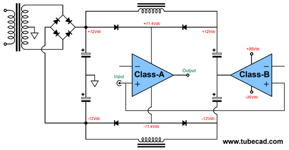
In this regard, this class-G version differs radically from the previous super class-A designs. In other words, we do not give the class-A amplifier's input and driver stages higher bipolar power-supply rail voltages. One way we could implement this scheme, without having to deal with multiple secondaries, is the following idea of mine. The two chokes allow DC current flow into the two capacitors that attach to the class-B amplifier's output. AC voltage swings, however, cannot be passed by the chokes. I must mention that this setup only works well with music playback, not sustained signal-generator output, as the floating capacitors are likely to suffer some discharge with prolonged steady sine-wave output. On the other hand, this setup will allow us to use a single secondary with even a stereo power amplifier.
The center-tap goes to ground and the outer taps go to the +/-35Vdc rails.
Class-G and Inductive Loads
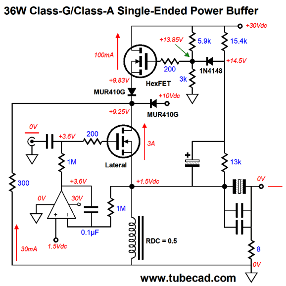
In general, MOSFETs are quite robust, but they have their limitations. For example, for most power MOSFET, the maximum gate-to-source voltage is +/-20V. Now, look at the schematic above and look for a potential problem. Can you spot it? The problem is that the inductive loading allows big negative swings of up to -24Vpk with an 8-ohm load. The top MOSFET, in contrast, cannot swing its source below ground potential (0V), so a very real danger exists when the speaker cable opens, unloading the inductor when the bottom MOSFET cuts off entirely. Such is the danger of the inductors. The workaround is to impose a hard lower limit to the gate voltage downward fall, which will not only protect the MOSFET's gate, it will prevent it from shutting off. Okay, now look at the following workaround.
Note how the 1N4148 will cease being forward biased when the output goes just a few volts negatively. But first, let's look at a big positive output swing.
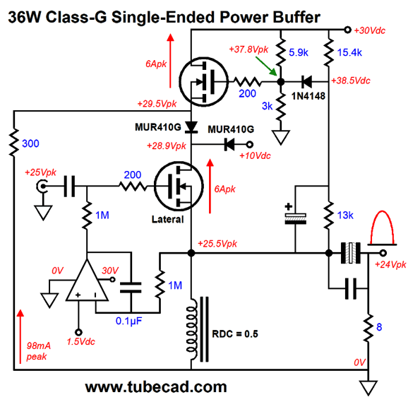
Okay, let's now look at a big negative output swing.
Notice how the 1N4148 is no longer forward biased and how the top MOSFET continues to conduct.
Music Recommendation: Nitin Sawhney's Live at Ronnie Scott's Imagine an album that somehow combines blues, country, flamenco, folk, funk with Indian ragas. If nothing else, the recording is excellent. Listen to the first track all the way through, before passing judgment. And if track seven, The Conference, does not bring a smile to your face, your eggnog needs more whiskey. Both Albums, Water and Live at Ronnie Scott's, are available at Tidal. //JRB
User Guides for GlassWare Software
For those of you who still have old computers running Windows XP (32-bit) or any other Windows 32-bit OS, I have setup the download availability of my old old standards: Tube CAD, SE Amp CAD, and Audio Gadgets. The downloads are at the GlassWare-Yahoo store and the price is only $9.95 for each program. http://glass-ware.stores.yahoo.net/adsoffromgla.html So many have asked that I had to do it. WARNING: THESE THREE PROGRAMS WILL NOT RUN UNDER VISTA 64-Bit or WINDOWS 7 & 8 or any other 64-bit OS. I do plan on remaking all of these programs into 64-bit versions, but it will be a huge ordeal, as programming requires vast chunks of noise-free time, something very rare with children running about. Ideally, I would love to come out with versions that run on iPads and Android-OS tablets.
//JRB
|
|
John Gives
Special Thanks to the Special 70
I am truly stunned and appreciative of their support. In addition I want to thank
All of your support makes a big difference. I would love to arrive at the point where creating my posts was my top priority of the day, not something that I have to steal time from other obligations to do. The more support I get, the higher up these posts move up in deserving attention. Only those who have produced a technical white paper or written an article on electronics know just how much time and effort is required to produce one of my posts, as novel circuits must be created, SPICE simulations must be run, schematics must be drawn, and thousands of words must be written. If you have been reading my posts, you know that my lifetime goal is reaching post 1,000. I have 554 more to go. My second goal is to gather 1,000 patrons. I have 929 patrons to go. Help me get there.
Only $12.95 TCJ My-Stock DB
Version 2 Improvements *User definable Download for www.glass-ware.com |
||


| www.tubecad.com Copyright © 1999-2018 GlassWare All Rights Reserved |