| John Broskie's Guide to Tube Circuit Analysis & Design |
28 January 2019 Post Number 454
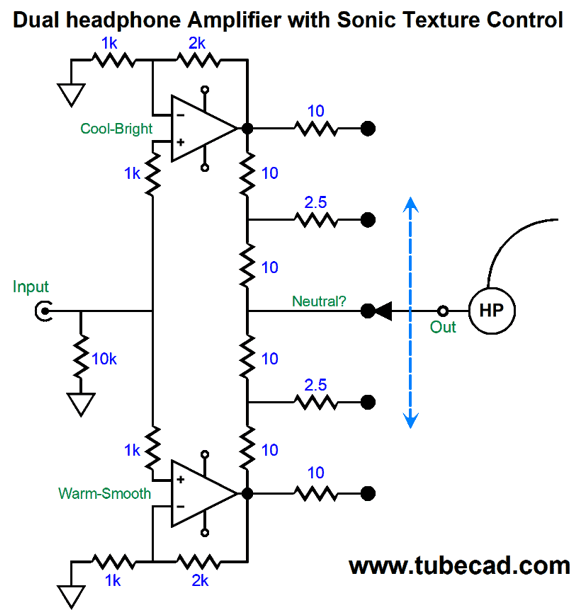
A Failed Successful Experiment In post 451, I described a means by which we could select a sonic fingerprint for our headphone listening by using two headphone amplifiers with diametrically opposed sonic overlays, one sounding warm and sweet, the other sound cold and hard.
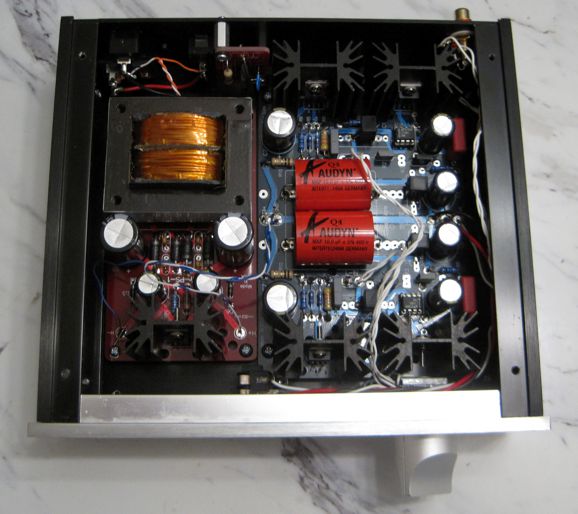
Well, I was keen to try this setup. I had already built up a sweet-sounding headphone amplifier, in spite of it being entirely solid-state and tube free. Thus, all I needed to do was build up its evil twin that would sound very solid-state. I used metal-film resistors and bulk-foil resistors in the feedback loops. I used OpAmps that slew at 1,000V/µs. I used German polypropylene bypass capacitors. I used a Tr-PS-1 regulator and transformer power supply, setup for +24Vdc of output. Alas, this new headphome amplifier, too, sounds sweet, very tube like. Dang. It's delicious, not a menacing alter ego. Double dang. Now, I have two sweet-sounding headphone amplifiers. I can listen to either all day long. What went right, when I wanted it to go wrong?
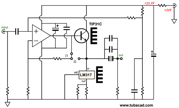
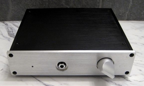
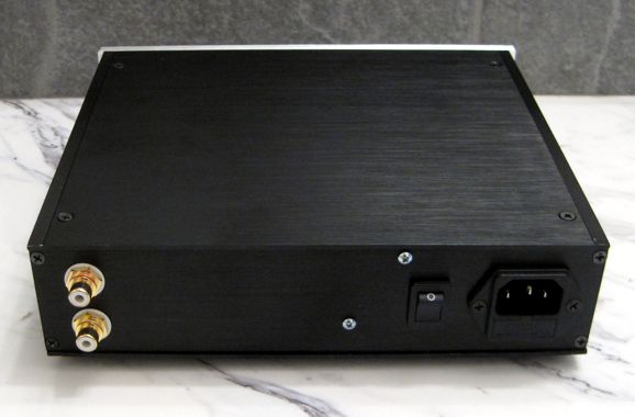
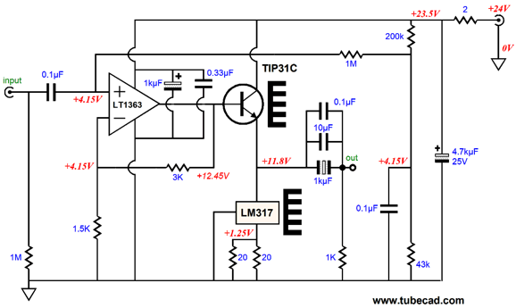
The circuit holds a single-ended output stage, which consists of an NPN power transistor and constant-current source. The two feedback resistor string terminates directly into ground; thus, DC current flow through them and forces the OpAmp to operate in a more single-ended fashion. The idle current through the transistor and CCS is a robust 125mA per channel. The negative feedback loop extends only to the transistor's base, not the emitter. The gain is just 3 (+9.5dB). I managed to squeeze everything thing, which included a regulated 24Vdc power supply and House-Ground PCB into a small enclosure from China.
The box came with all the holes pre-drilled or punched, which helped a lot.
It was a crazy tight fit. Needlessly tight. I am cursed with the ability to stuff much into small containers. I wish it were otherwise. Just because I can fit so much into so small a box does not mean that I should. I wish that I had picked an enclosure several inches wider and deeper, as I would prefer to put some distance between power sully and amplifier PCB. Still, the headphone amplifier is silent.
Here is the schematic with the part values I used.
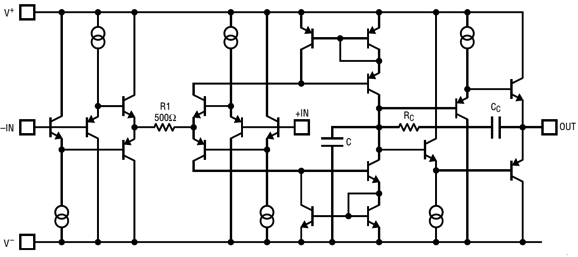
The Linear Technology (i.e. Analog Devices) LT1363 is an interesting OpAmp that uses a current-feedback topology. Here are its features from its datasheet:
Its internal topology consists of three diamond circuits, one of which is used to drive the low-impedance inverting input; another of which is used as the output stage.
To my ears, my new headphone amplifier using the LT1363 sounds much like the Texas Instruments TPA6120A2 stereo 3W headphone amplifier OpAmp, which slews at 1300V/µs. I believe the TI OpAmp was originally intended for video amplifier use, but someone hooked up headphones to it and it found a new use. Here is the amazing thing, how is that the most advanced and fastest solid-state amplifier sounds like tubes that were made almost one hundred years ago? My original sweet-sounding headphone amplifier used the exact same circuit and PCB, but held carbon-film resistors and different bypass capacitors. It also used the OPA627, which is the unity-gain stable version of the OPA637. Okay, back to my question, What went right? My guess is that the ultra-fast LT1363 helped a great deal, as did the feedback-free, single-ended output stage. (My initial reaction was: Mercy, this sounds single-ended.) In my new version, I used an Alps carbon-film volume control, which is no longer being made, as far as I can tell, which is a shame, as it sounds quite good and is tiny. So, how am I going to alter my second headphone amplifier to get to a more strident-sounding flavor? A different OpAmp would be a good start and enclosing the output stage within the negative feedback loop would probably help by erasing some of the even harmonic distortion. Perhaps, the bulk-foil resistors and carbon-film potentiometer will have to go as well.
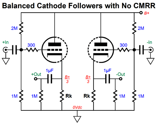
Balanced (Differential) Cathode Followers
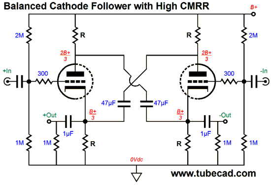
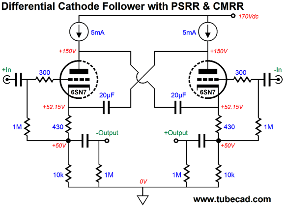
This is why I invented the Broskie cathode follower (BCF), as wanted to attain CMRR and low output impedance from a balanced unity-gain buffer circuit. Another alternative to just using two cathode followers is to use the balanced cathode follower from post 371.
The cross-coupled 47µF capacitors lock the two triodes together, so that balanced input signals easily pass, but unbalanced signals common to both inputs are ignored.
The output impedance is a bit paradoxical, as when measured from output to output yields a low 140 ohms, but when measure from ground to either output we measure a high 2550 ohms. Effectively what we have here is cross-coupled split-load phase splitters. While the CMRR is good, the circuit shown above's PSRR is poor, coming in at only -6dB, far worse than the typical cathode follower. One workaround is to replace the plate resistors with constant-current sources (CCS), which will shield the follower from the power-supply ripple.
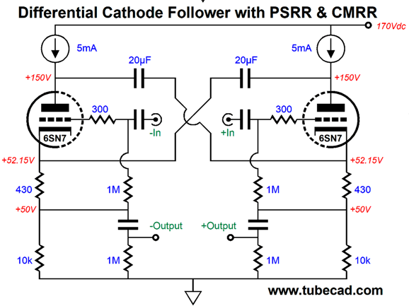
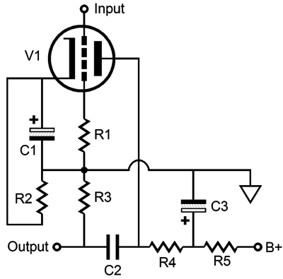
Okay, as I look at the schematic above, I am troubled by how complicated it appears. Back in post 300, I gave an example of how a familiar circuit can appear strange and undecipherable when drawn in a non-standard fashion. What do you think about the following circuit? Is your mind blown? Have you ever seen anything like it before?
I am going to force you to follow the link to post 300 to see it redrawn. Okay, now let me redraw the differential cathode follower.
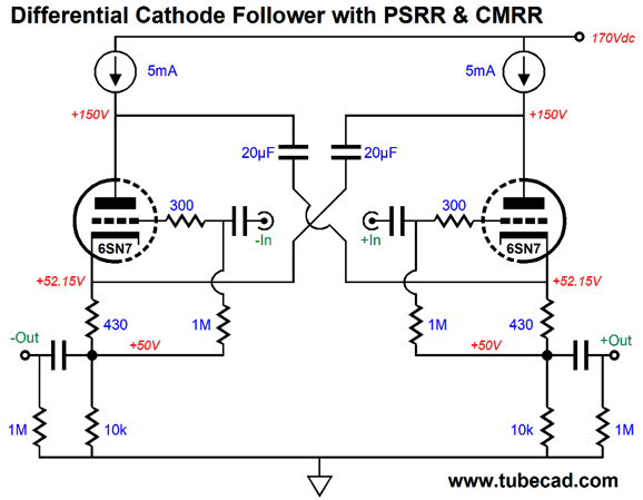
Better, but still a tad confusing. Here is my last try.
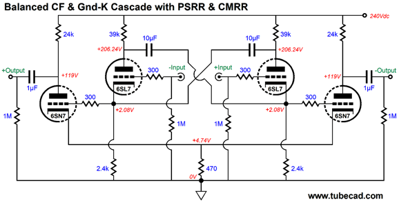
Since we read from left to right, this last version probably makes the most sense to out mind. Well, all of this was a preamble to a circuit I should have shown in my last post: the balanced cathode-follower and grounded-cathode amplifier cascade with high PSRR and high CMRR.
Strangely enough, this was the first rough sketch I made, but I then forgot about it. I have since modeled it in SPICE and the results are gratifying. My goals were to achieve a low input capacitance and a good PSRR and CMRR—along with using a 6SL7 and 6SN7.
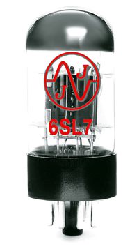
JJ is now making a 6SL7, which I have bought, but yet to test.
A New Use for a New Audio Product
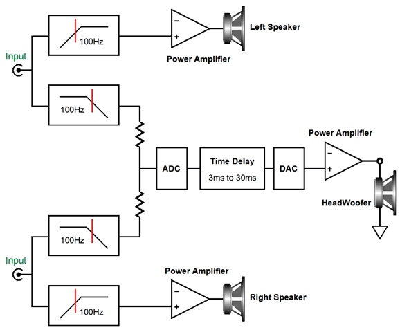
Alas, there one flaw to Budi's reasoning: time. It takes time for the sound leaving your main speakers to get to your ears, but very little time for the sound leaving the the HeadWoofer to arrive. Sound travels roughly at 1 millisecond per foot and the ear complains if two sound sources differ by more than about 3 milliseconds, which was discovered back when talkie movies were introduced and they discovered that the tweeter had to be within that 3 millisecond time-alignment window with the woofer or the viewers would complain of the tap dancers on the screen double-tapping each step. Of course, the best setup is perfect time alignment. About ten years ago, I visited a friend of a friend and beheld his mega-expensive stereo system. He used two huge subwoofers that were fed from two bridged stereo amplifiers that put out about 500W each in that mode. (My quick estimate was that just his subs and amplifier and active crossovers alone cost well over $10,000.) He placed the two subwoofer at the sides of his listening chair and used them as tables.
So how did it sound? Well, it sounded just the way he wanted it to sound. MASSIVE BASS. I asked him to reduce the bass level for me and the bass still seemed majorly off to my ears, sounding as if it were tuned to a different station. At the time, I blamed the active crossover, but a better guess would be that the time discrepancy was far to great, with the bass hitting the ears far before the rest of the sound did, as the main speakers were at least fifteen feet away. (Here is the small paradox: he listened primarily to jazz, folk, and classical music—all of it non-electronic in nature, being acoustic in the extreme, which made the time-lag even more painful.) In other words, I have already heard the HeadWoofer with speakers idea and I found the non-time-aligned results wanting. The workaround would be to impose a time delay on the HeadWoofer's input signal equal to the time it takes the main speakers to reach your ears. Ideally, an active crossover would be used to impose a high-pass filter on the signal going to the main speakers, which could be purposely flow-frequency-limited, say small mini monitor types; and impose low-pass filter upon a stereo-to-mono blending of the stereo signal for the HeadWoofer.
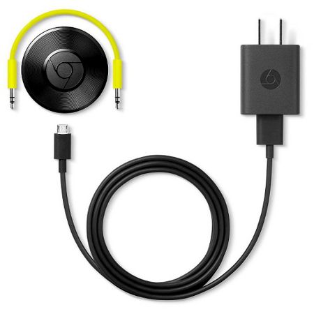
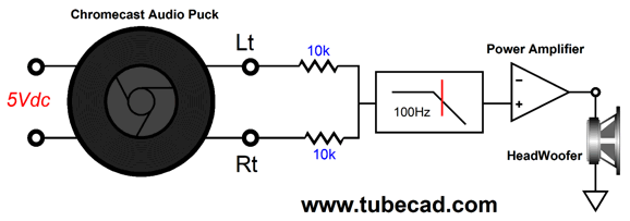
If you are running a music server signal source, then the cheapest and easiest approach would be to use a Google Chromecast Audio puck.
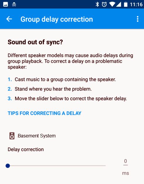
I beat the poor Google Chromecast Audio puck to death in posts past, such as post 383 and post 384 and post 388 as I came up with many possible uses for the tiny WiFi DAC, which now cost only $15. The puck is controlled by an app that allows you create groups of pucks and to apply time delay to a desired puck. We can easily adjust the time delay on the fly. (I believe the delay can range from zero to 100 milliseconds.)
But is the Chromecast Audio puck HiFi? The internal DAC is a 24-bit/96KHz type, which although not cutting edge, is plenty good enough for frequencies below 100Hz. But what about the main speakers?
The Chromecast Audio puck offers two outputs: stereo analog and digital optical. Thus, by using an optical link to an expensive and fancy DAC, we can bypass the DAC within the Chromecast Audio puck. In other words, a proof of concept would not be that hard to test.
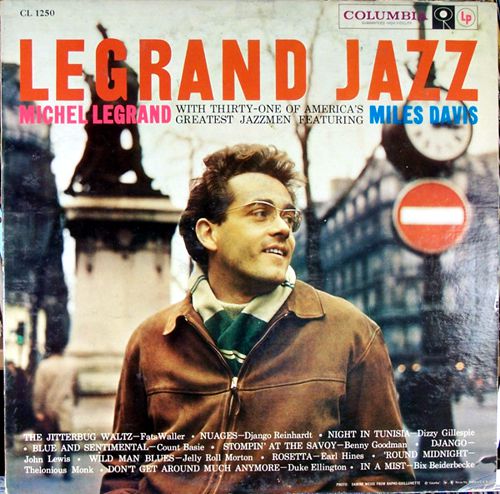
Music Recommendation: Michel Legrand's LEGRAND JAZZ
//JRB
If you enjoyed reading this post from me, then you might consider becoming one of my patrons at Patreon.com
User Guides for GlassWare Software
For those of you who still have old computers running Windows XP (32-bit) or any other Windows 32-bit OS, I have setup the download availability of my old old standards: Tube CAD, SE Amp CAD, and Audio Gadgets. The downloads are at the GlassWare-Yahoo store and the price is only $9.95 for each program. http://glass-ware.stores.yahoo.net/adsoffromgla.html So many have asked that I had to do it. WARNING: THESE THREE PROGRAMS WILL NOT RUN UNDER VISTA 64-Bit or WINDOWS 7 & 8 or any other 64-bit OS. I do plan on remaking all of these programs into 64-bit versions, but it will be a huge ordeal, as programming requires vast chunks of noise-free time, something very rare with children running about. Ideally, I would love to come out with versions that run on iPads and Android-OS tablets. //JRB |
John Gives
Special Thanks to the Special 74
I am truly stunned and appreciative of their support. In addition I want to thank the following patrons:
All of your support makes a big difference. I would love to arrive at the point where creating my posts was my top priority of the day, not something that I have to steal time from other obligations to do. The more support I get, the higher up these posts move up in deserving attention. If you have been reading my posts, you know that my lifetime goal is reaching post number one thousand. I have 546 more to go. My second goal is to gather 1,000 patrons. I have 926 patrons to go. Help me get there.
Support the Tube CAD Journal & get an extremely powerful push-pull tube-amplifier simulator for TCJ Push-Pull Calculator
TCJ PPC Version 2 Improvements Rebuilt simulation engine *User definable
Download or CD ROM For more information, please visit our Web site : To purchase, please visit our Yahoo Store: |
|||
| www.tubecad.com Copyright © 1999-2019 GlassWare All Rights Reserved |
