| John Broskie's Guide to Tube Circuit Analysis & Design |
29 April 2019 Post Number 463
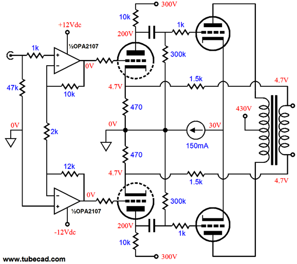
Okay, I admit that this sounds like a crazy idea, as the tube-based amplifier will be huge and cost a fortune. Or would it? What if we limit the bandwidth to 20Hz to 200Hz? What if we use a toroid power transformer as the output transformer, as 500VA toroids can be had for less than $60? What if we used high-voltage OpAmps to drive the output tubes? Four KT88 output tubes can easily deliver 100W in pentode mode. Negative feedback works well with low frequencies, but not high-frequencies, so the high-voltage OpAmps can tightly control the amplifier's output. Or, we might forgo the OpAmps and build something like this.
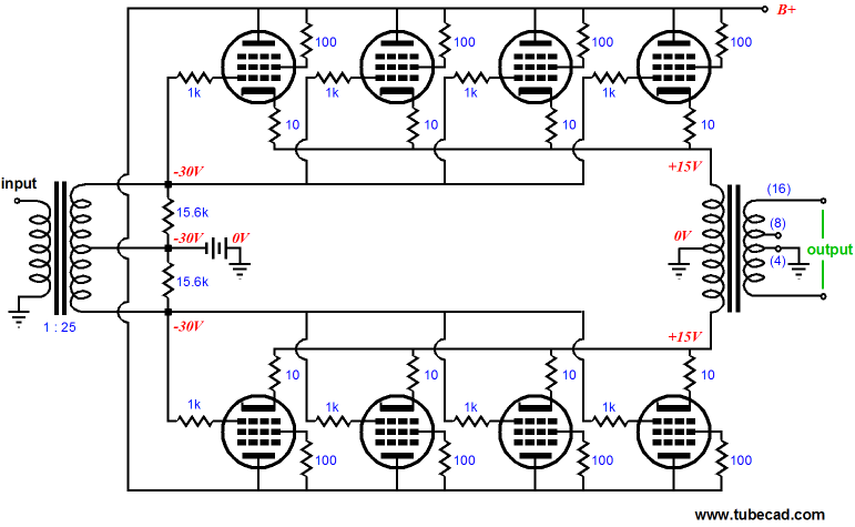
Once again, we would usea toroid power transformer as the output transformer. And due to the limited bandwidth of only 20Hz to 200Hz, we could probably get away with using a flat-pack power transformer as the input signal transformer. Note that this amplifier works in cathode-follower mode. The remaining question is: Would the tube-based subwoofer amplifier sound better than the solid-state class-D subwoofer amplifier? It just might. At the other extreme, we could give each loudspeaker its own internal solid-state amplifier and external switcher power supply, say a 48V switcher with 10A of output current. Since this power supply would be monopolar, we would have to use both an input coupling capacitor and an output coupling capacitor.
Or would we? What follows is a topology that effectively creates a bipolar power supply out of a floating monopolar supply. The key word in that last sentence was "floating," i.e. not grounded. In other words, if the putatively "floating" switching power supply attaches its negative output terminal to the house ground, it's not floating. Check and measure first, don't swear later.
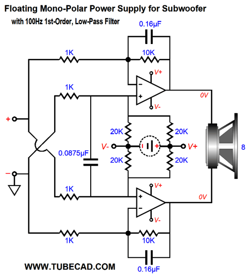
Yes, it looks quite balanced, which it is at its output. But look at its input, where we see a ground connection. Of course, we could remove the ground symbol and treat the input as being balanced as well. (In theory, two channels could share the same floating power supply, but I wouldn't be inclined to do it.) As far as each of the two amplifiers are concerned, the 8-ohm subwoofer is a 4-ohm load, so unless the amplifiers are robust enough to drive a 2-ohm load, do not use a 4-ohm subwoofer. (At the center of the voicecoil, 0V falls, no matter how much voltage swing the positive and negative terminals see.) I remembered this arrangement when I was thinking about the Headwoofer for headphone listening with a deep bass boost. For that application, we might get away with 1st-order low-pass filter at 100Hz.
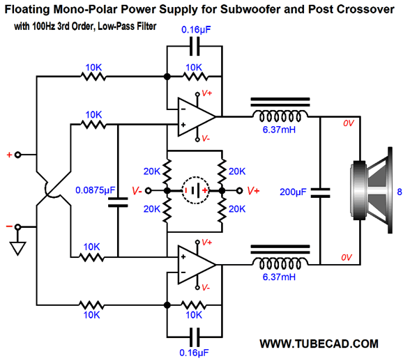
If a steeper we could cascade a differential 2nd order low-pass filter with a Q of 1 in front of the two power amplifiers or we could add a passive filter after the two power amplifiers.
Note that inductors are chosen to match a 4-ohm load, but the capacitor was selected to work with an 8-ohm load. (If we had used two 400µF capacitors in series, the right value for a 4-ohm load, the two would reduce to 200µF, as capacitor in series are like resistors in parallel.) Of course, using the passive crossover brings back the problem of big inductors and capacitors. By the way, with a 48V floating power supply and a differential output, we should easily be able to get 40Vpk output swing across the 8-ohm subwoofer, which would translate into 100W. In contrast, a bipolar power supply with +/-24Vdc power-supply rails and true ground connection would yield only 20Vpk voltage swings and 25W. Nonetheless, a Headwoofer could probably get away with a 24V floating power supply, as 25W going to a woofer inches away from your ears would prove plenty loud. One workaround to the shallow 1st-order crossover is to create a faux ground and use the same balanced power amplifier setup.
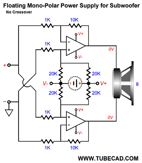
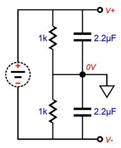
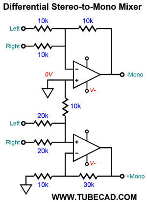
This simple circuit splits the monopolar power supply into to positive and negative power-supply-rail voltages. This circuit cannot work with a single power amplifier, as the ground cannot sustain big current or low-frequency swings. The next step is to create a balanced summing circuit that will combine the left and right channel signals into a single mono signal for the Headwoofer or subwoofer.
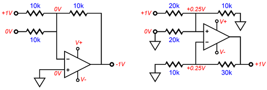
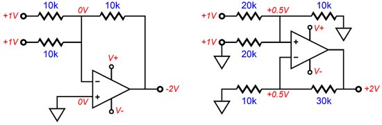
The top half of the circuit is a simple inverting mixer (or summing) circuit. If the left channel presents 1Vdc and the right channel presents 0Vdc, then the mixer output will be -1Vdc; if both channels present 1Vdc, then the output will be -2Vdc. The bottom half of the circuit is more interesting, as it is a non-inverting mixer. The implicit assumption is that the left and right signal sources deliver a low output impedance at their outputs, so when no signal is present they resemble dead shorts to ground.
If the left channel presents 1Vdc and the right channel presents 0Vdc, then the 1Vdc will be voltage divided down to 0.25Vdc, as the right channel's 20k resistor is effectively in parallel with the 10k resistor to ground, making a parallel resistance of 6666 ohms.
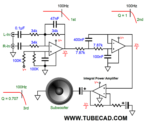
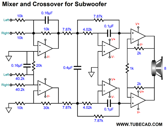
The OpAmp's negative feedback resistors set a gain of 4, so the OpAmp's output is +1Vdc. If both channels present 1Vdc, then the output will be +2Vdc, as the two 20k resistors are effectively in parallel, making a 50% voltage divider with the 10k resistor to ground; the voltage divider presents 0.5Vdc, which the OpAmp amplifies up to 2Vdc. With top and bottom mixer circuits combined, we get a balanced mixer output. Next, we add a 100Hz, 1st-order, low-pass filter to both mixer sections and then cascade into an MFB differential 2nd-order 100Hz filter with a Q of 1. The multiple feedback filter (MFB) is far better than the Sallen-and-Keys type, due to its inverting nature.
At the very right are the two power amplifiers that actually drive the subwoofer. In this example, their gain is 5. (Your guess was either 2 or 3, right?) Imagine that instead of one 1k resistor, we had used two 500-ohm resistors, with their nexus going to ground. Well, the gain would then be equal to (2k + 500)/500 or 5 or +14dB. Of course, less or more gain might be needed. The key point is that the differential arrangement allows us to bypass the problem of ground with a monopolar power supply. Of course, there are times when we must resort to an old-fashion bipolar power supply. The advantage that the standard full-wave center-tap rectified power supply offers is that it is crazy reliable. In contrast, the switching power supply offers a lighter, smaller, cheaper, more flexible solution. And flexible they are, as most accept a wall voltage between 90Vac to 260Vac and still deliver the specified output voltage within 2%. Alas, as they are vastly more complicated, they are less reliable. By the way, they do make switcher power supplies in modular form that are meant to be mounted in an enclosure. Two low-voltage switchers can be placed in series, which will create a bipolar power supply. Here is the thing: I am happy to place switcher power supply modules within a metal chassis, but I worry about doing the same within a wood enclosure. Why? The metal acts as a heatsink, so the convection air currents within the metal enclosure spread the heat throughout and the metal box radiates heat, cooling the parts inside. Wood, in contrast, is a great thermal insulator. In addition, speaker enclosures are often filled with fiberglass or polyester or wool batting. Great for keeping you warm; bad for keeping you cool. Then there's the danger of the wood catching on fire, should the switcher power supply go up in flames. Paranoia persists because it persistently pays off.
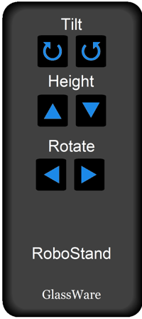
I still think that someone should make a powered speaker stand that comes with a remote, so we could adjust the toe-in and height and backward tilt from our listening chairs. I called this the RoboStand back in post 279. Well, the active speaker stand would be a great place to house an external power supply for the speaker's integral power amplifier. The question to ask now is, Is it possible to use a monopolar power supply in a floating configuration and not use input and output capacitors? It is.
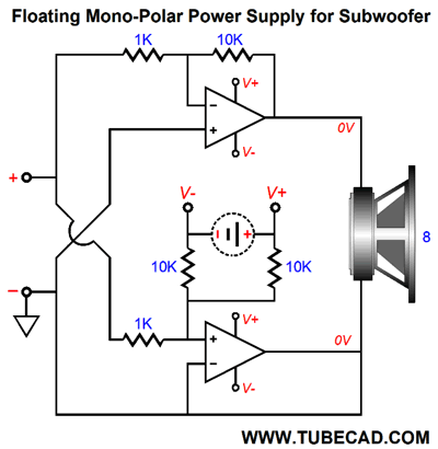
Using a Floating Power Supply with Grounded Input and Outputs
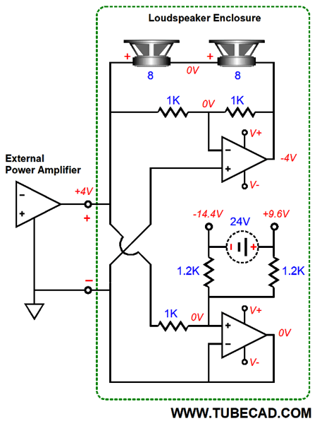
The input is grounded. The output is grounded. The top power amplifier is configured as a simple inverting amplifier. The bottom power amplifier seems to be either doing nothing or going to blow up as its output is shorted to ground. In truth, the bottom amplifier is effectively in series with the top amplifier and what it drives is the floating monopolar power supply. Let's add some representative DC voltage at idle.
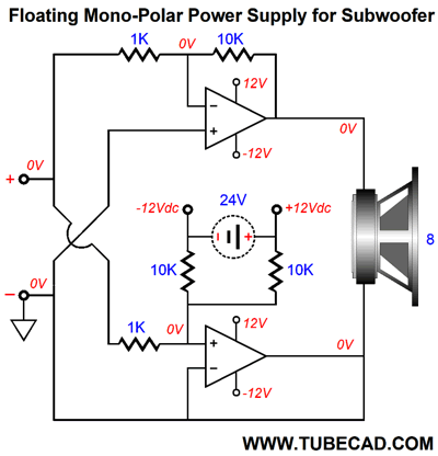
The floating power supply's 24Vdc seems puny, seemingly implying output voltage swings no greater than +/-10Vpk if we are lucky. This peak voltage implies only 6.25W into an 8-ohm load. But the arrangement yields an output closer to +/-20Vpk and 25W. How is that possible? The answer is the the floating power supply moves with the top amplifier output voltage swing. As the top amplifier's output swings positively, so, too, the floating power supply's relation to ground alters, making the voltage division favor the positive voltage.
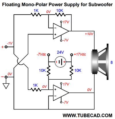
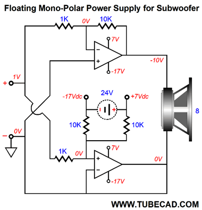
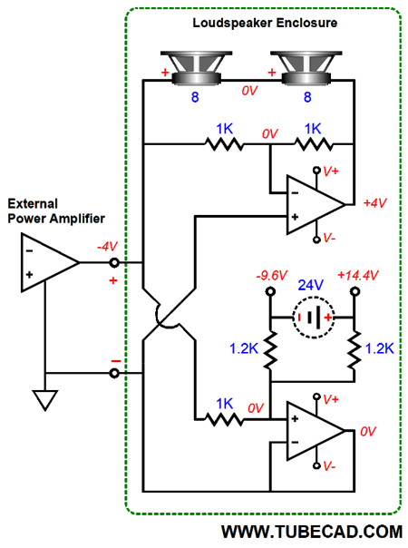
The -1Vdc input voltage causes the top amplifier to invert and amplify the voltage to +10Vdc. The bottom amplifier is effectively also an inverting amplifier, appearances to the contrary. Its gain is 5, not 10, so the floating power supply must shift positively by 5Vdc, which gives the top amplifier more positive power-supply rail voltage to work with. A +1Vdc input voltage forces both the top and bottom amplifier to go negative.
The floating power supply shifted negatively by -5Vdc, which gives the top amplifier an extra -5Vdc negative power-supply rail voltage. Because the two power amplifiers are effectively in series, the voltage drops add up. For example, if the amplifier's output can swing within 2V of the power-supply rail voltages, then the two 2V voltage drops will add together and make a 4V voltage drop. In other words, in this example with the 24V floating power supply the peak output voltage swing would be +/-20V. Note that we didn't have to use either an input or output coupling capacitor, which is a huge plus. Bear in mind, however, that any DC offset at the input will get amplified at the loudspeaker. My assumption is that either a tube-based OTL with a coupling capacitor or typical transformer-coupled power amplifier will be used, so no DC offset will or can be present.
A Word About SPICE The workaround was to create SPICE models of OpAmps that deliver the expected behavior for most uses. Of course, when the maker designed the actual OpAmp, the electrical engineers did make huge and complex SPICE circuits that did include most if not all the internal parts. They were willing to wait for results to pour out. When I first ran SPICE simulations on this circuit, I got crazy results. I was sure that my cutting and pasting was at fault, as node designaters get copied as well and resulting circuit hold shorts that you cannot see in the schematic. That wasn't it. It was the Burr-Brown OpAmp model. I replaced it with an Analog Devices AD843 model and the expected results resulted.
The moral here is that although SPICE is marvelous, you get the most out of it when you already know the results. Or, rather, when you are able to know when SPICE has gone off the rails. Many do not. I get SPICE created circuits from readers that rely on SPICE getting it wrong to work. In general, any SPICE circuit that uses constant-current source is suspect. A quick test is the set the power-supply voltages to zero and then see if you get output voltage swings. If you do, ponder how that is possible with no power source. Have you created something out of nothing or has some SPICE shortcut fooled you? For example, in SPICE, vacuum tubes are modeled as variable current sources, when in fact they are variable resistances. On its own, a triode does not generate any current flow. In SPICE, it can. Okay, having said all that, I must admit that SPICE had proved useful, as it made me realize that my first attempt at the circuit had the bottom amplifier set to the same gain as the top amplifier, i.e. 10. A mistake. A gain of 5 was far better, as we do not want either the positive or negative rail voltages to get too close to 0V, as the amplifier's input stage needs a certain amount of voltage headroom within which to work. Now, if a 48V floating power supply were used, we would bring the bottom amplifier's gain up something closer to the top amplifier's gain.
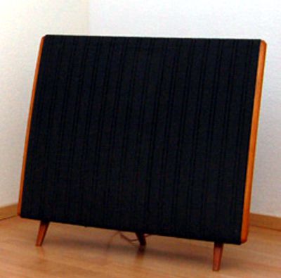
Tribute to Quad 57
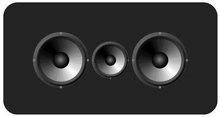
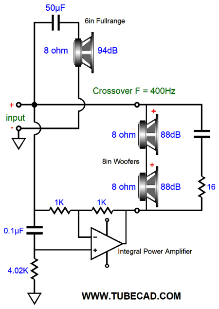
My mind returns to the Quad model 57 electrostatic loudspeaker. I loved this speaker at first listen. It sounded so right and it revealed the sonic differences between amplifiers instantly, whereas most box loudspeakers sounded muddled by comparison. In college, I built several dipole loudspeakers with dynamic drivers that I had hoped to capture some of the Quad's coherence and delicacy, but without its physical fragility. My friend owned a pair of Quads and he sat, as the music swelled to a crescendo, in nervous fear of an arc. Well, I would like to resume this quest today. I would like to assemble a dipole loudspeaker that uses a single 6in fullrange driver from 400Hz up and two 8in woofers below 400Hz in the original Quad 57 configuration, with the woofers straddling the fullrange.
Dayton makes a fullrange 6in that offers an SPL of 94dB at 1W. Most HiFi woofers fall far short of that efficiency, with 88dB being closer to average. Well, two 88dB woofers placed in parallel will deliver 94dB with 2.86Vpk of signal, as the emitting surface has doubled. Alas, the impedance has halved, so the power delivered has doubled. (Normally, doubling the power only gives a 3dB boost.) On the other hand, if we place the woofers in series and double the applied voltage swing, we get the same 6db boost, but at the same peak current flow.
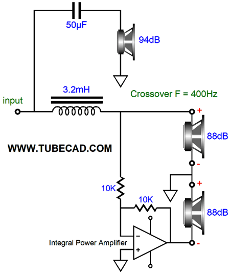
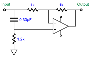
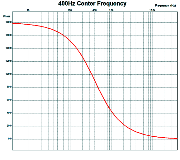
The external flea-powered tube amplifier drives the fullrange completely and it drives the two woofers half the way with the integral power amplifier driving the other half of the way. The integral power amplifier inverts its input signal, so each woofer sees the same voltage that one woofer would see with only the flea-power amplifier. The crossover inductor's value matches an 8-ohm load, not a 16-ohm load, as the nexus between the woofers is effectively grounded, as zero volts develop there. Ideally, I would want to use a first-order crossover, as it delivers a flat phase and places less stuff between the signal. In addition, I would love to lose the inductor. This brings me back to the phase-shifting circuit that I have shown here before in post 261 (well worth checking out).
DC voltages and low frequencies are inverted at the integral power amplifier's output. In contrast, high-frequencies are delivered in phase with the input signal. The frequency response is flat.
But as far as the two woofers are concerned, they see a first-order low-pass filter at 400Hz. Think about it: if the flea-power amplifier's output voltage gets inverted at the integral power amplifier's output, the woofers see twice the external amplifier's output voltage. But if the flea-power amplifier's output is not inverted and is presented at equal magnitude, the woofers effectively see zero voltage, as there is no voltage differential across their terminals.
The flea-power amplifier is still producing the high-frequencies, but they are invisible to the woofers. The flea-power amplifier's input signal can be filtered, say with a 100Hz first-order high-pass filter, so that the loudspeaker could be augmented with a subwoofer. Another possibility would be to use the integral power amplifier's output to augment the fullrange's output.
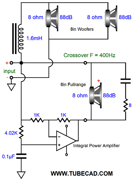
The two 8-inch woofers are placed in parallel and enjoy a 6dB boost in SPL, but do present a 4-ohm load, which explains why the crossover inductor is seeemingly low in value for a 400Hz crossover frequency. The phase shifter resistor and capacitor have been flipped, so the fullrange sees a 400Hz high-pass, first-order filter. DC voltages and low frequencies are in phase at the integral power amplifier's output, so the fullrange cannot see them as it sees no voltage differential. The 8-ohm fullrange appears a 4-ohm load to the external power amplifier, so the entire speaker impedance is 4 ohms. By the way, they do make 4in and 5in fullranges with efficiencies of about 88dB, so this setup might prove more useful than I expected. Here is where the grounded input and output two-amplifiers with a floating power supply come in handy.
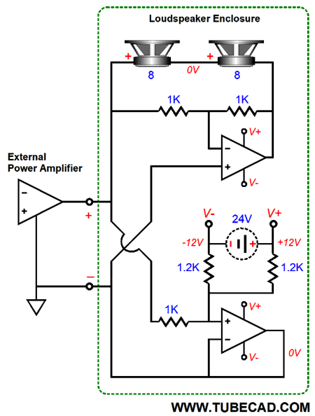
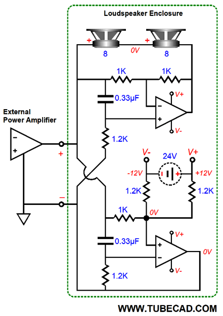
The 24V floating power supply powers both integral power amplifiers. The phase-shifting circuitry is not shown, for clarity's sake. If it helps, imagine that the two drivers are fullranges, one firing forward, the other rearward. In this arrangement, the loudspeaker's impedance would appear as 8 ohms to the flea-power amplifier. Note the two 1.2k resistors that attach to the 24V floating power supply. You might imagine that two 2k resistors would prove better, but they do not. We do not want the power-supply rail voltages to move as much as the top amplifiers output does. Thus, the two 1.2k resistor from a 600-oh resistance in series with the 1k resistor and reduce the bottom amplifier's gain to 0.6 rather than unity gain. Now, let's look at what happens when the flea-power amplifier puts out 4Vpk (1W into 8 ohms).
The flea-power amplifier is putting out 4Vpk, while the integral inverting power amplifier does the same, but inverted, so each speaker driver sees 4Vpk across its terminals. The result is that we get a 6dB boost in SPL from our flea-power amplifier and integral power amplifier.
As long as the flea-power amplifier does not put out more than 25W, the 24Vdc floating power supply can keep up with it. On the other hand, if the external power amplifier delivers up to 100W, then a floating 48Vdc power supply should be used. Okay, it is now time to show the phase-shift low-pass crossover in place.
I know that some readers are thinking, why not just pad the fullrange by -6db, so this elaborate setup can be bypassed and a conventional loudspeaker can be made by anybody marginally skilled? Sure, but you will get no power boost and you will still have the large inductor in series with the woofers. (Two 4-ohm woofers would be used for a final 8-ohm impedance. Or, if you are willing to have a 16-iohm loudspeaker, two 8-ohm woofers would be used and an 8-ohm series resistor would be placed in series with the fullrange. This 16-ohm would work well with tube amplifiers that offer a 16-ohm tap on the secondary.) By the way, the woofers do not have to be used as dipoles, as they could each get their own back enclosure, as at frequencies below 400Hz, they will radiate fairly omnidirectionally. In other words, the reflected sound would still present the same frequency spectrum as the front radiation, albeit with some phase shift. But then, all of a dipoles rear radiation is out of phase. Beside the reflected sound will bounce about and make a phase stew, with some frequencies hitting your ears in phase, while most will be phase shifted. In other words, do not worry about reflected phase, worry about reflected frequency spectrum. Your average front-firing dynamic loudspeaker is omnidirectional at low frequencies, but severely directional at high-frequencies.
When I first heard MQA unfolded by my DAC, I thought, "Sure it sounds great, but perhaps too great, like a beautiful a woman seen at a distance, but who close up reveals gobs of makeup. Well, after hundreds and hundreds of hours to listening to MQA and plain 16-bit FLACK files and high-resolution files, I have to admit that I still like MQA and I don't think that I am being duped. And even if I am, who cares? I will now quote myself from five years ago, in post 311.
Music Recommendation: Female Singers
My answer was Aldous Harding. Her name just plopped instantly out of my mouth, with neither deliberation nor habit to explain it. She asked what was so special about Harding's singing and my answer was that her songs haunt me long after I hear them. This New Zealand singer sings with many different voices and all her songs have an unsettled quality, as if each song were a new exploration by her and she herself didn't know what she would encounter or end up. I cannot think of any other singer like her. I have seen her compared to Kate Bush, but that is too much of a stretch for me, but I can see why the comparison is made. Well, Aldous Harding has new album, Designer, which appears on Tidal.
It's a bit more upbeat than her last album, Party, and I plan on listening to it over and over again. Most audiophiles already know Shelby Lynne due to her album, Just a Little Lovin' and her cover of the song, "The Look of Love." I like her a great deal, but I hadn't paid much attention to her lately, so I went hunting on Tidal and I found her 2015 album, I Can't Imagine. Dang, I wish I had heard it four years ago when it came out, as it is an excellent showcase for her immense talent, both as a songwriter and singer.
Her songs span several genres, from country to pop to alternative. Tidal offers this album in MQA and it sounds great. I stumbled across the next album at Tidal and I am glad I did, as it delivers almost two hours of fine female singing, from singers both famous and not so famous...or not yet famous.
//JRB
If you enjoyed reading this post from me, then you might consider becoming one of my patrons at Patreon.com
User Guides for GlassWare Software
For those of you who still have old computers running Windows XP (32-bit) or any other Windows 32-bit OS, I have setup the download availability of my old old standards: Tube CAD, SE Amp CAD, and Audio Gadgets. The downloads are at the GlassWare-Yahoo store and the price is only $9.95 for each program. http://glass-ware.stores.yahoo.net/adsoffromgla.html So many have asked that I had to do it. WARNING: THESE THREE PROGRAMS WILL NOT RUN UNDER VISTA 64-Bit or WINDOWS 7 & 8 or any other 64-bit OS. I do plan on remaking all of these programs into 64-bit versions, but it will be a huge ordeal, as programming requires vast chunks of noise-free time, something very rare with children running about. Ideally, I would love to come out with versions that run on iPads and Android-OS tablets. //JRB |
John Gives
Special Thanks to the Special 80!
I am truly stunned and appreciative of their support. In addition I want to thank the following patrons:
All of your support makes a big difference. I would love to arrive at the point where creating my posts was my top priority of the day, not something that I have to steal time from other obligations to do. The more support I get, the higher up these posts move up in deserving attention.
If you have been reading my posts, you know that my lifetime goal is reaching post number one thousand. I have 537 more to go. My second goal is to gather 1,000 patrons. I have 918 patrons to go. Help me get there.
Support the Tube CAD Journal & get an extremely powerful push-pull tube-amplifier simulator for TCJ Push-Pull Calculator
TCJ PPC Version 2 Improvements Rebuilt simulation engine *User definable
Download or CD ROM For more information, please visit our Web site : To purchase, please visit our Yahoo Store: |
|||


| www.tubecad.com Copyright © 1999-2019 GlassWare All Rights Reserved |