| John Broskie's Guide to Tube Circuit Analysis & Design |
|
11 November 2019 Post 482
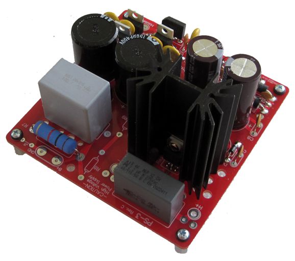
PCBs Arrive!
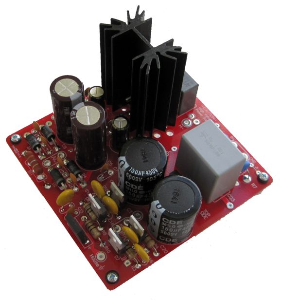
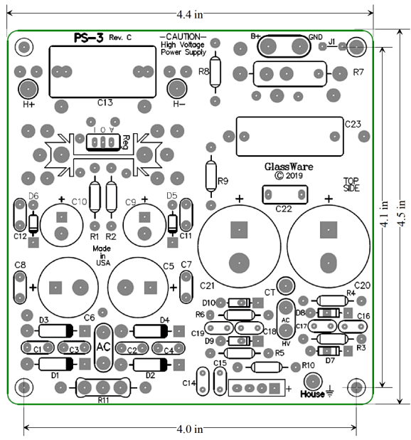
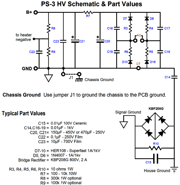
PS-3 Rev. C In the photo shown above, we see the optional HEXFRED® ultrafast soft recovery rectifiers being used. (I plan on building a new 6SN7-based headphone amplifier with this very PCB.) Well, the PS-3 is now in revision C. It's slightly larger, 4.4in by 4.5in, compared to the old 4in by 4in PCB. I had to make it larger to hold a 10µF/700V polypropylene output bypass capacitor and the LV-Regulator's circuit, which holds an input RC filter.
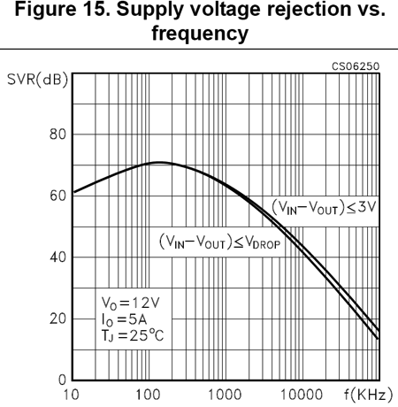
For high-quality audio work, I like to use an RC pre-filter before the voltage regulator, as it greatly unloads the regulator and improves the PSRR. Here is the graph from the LD1084's datasheet that shows its PSRR vs frequency.
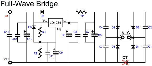
Note that it peaks at 120Hz (-72dB), which is great, but also note how at 20kHz the PSRR is only -35dB, not so good. Placing an RC filter whose transition frequency is 300Hz or lower before the regulator prevents the high-frequency droop. (In fact, some high-voltage regulator designs simply fail to work without an RC pre-filter on the raw DC voltage entering the regulator.) The LDO84 adjustable low-dropout-voltage regulator is rated for 5A of output. In the schematic shown below, we see at the low-voltage regulator's output a 2.2µF polypropylene bypass capacitor (C13).
The high-voltage power supply isn't regulated, but it does use an RC filter at its output. (Resistor R7 could be replaced with an external choke.) A house-ground circuit is implemented as well.
All in all, this is one sweet tube-circuit power supply. With the 470µF/250V capacitors and a 120Vac secondary, we get about 170Vdc before the RC filter, which is perfect for most tube-based headphone amplifiers and many line stage amplifiers. With the 150µF/450V capacitors and a 240Vac secondary we get about 330Vdc, which can power phono stages and even small power amplifiers.
The new PS-3 Rev. C is available at my GlassWare-Yahoo store and at the same price as the Rev. B version.
Tube Dream
Well, I wish we tube-loving folk had something similar, say a yearly home-built tube audio equipment contest. Where would the event be held and who would judge? Much like the ETF (European Triode Festival), which hosts a several-day event for about a hundred tube-loving attendees, the tube contest would have to be held at a retreat somewhere in the middle of America.
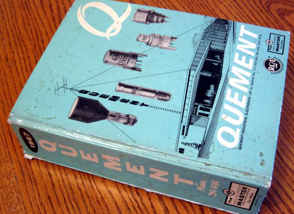
In other words, we need an American Tube Festival, where we tube-lovers would meet, talk, drink, listen, and judge audio shootouts. Imagine if such a contest were held with several categories, such as power amplifiers, line-stage amplifiers, phono preamps, headphone amplifiers, test equipment, exotica (things like tube-based equalizers and active crossovers and hybrid DACs), then each category would further subdivide into Most-Bang-per-Buck, The Absolute, Highest Craftsmanship… The sub-category I would most like to see is best retro design, i.e. a design that could have been built in 1967, with the available parts back then, had they the inspiration and insight. I have mentioned this daydream of mine several times before. Here is what I said five years ago in post 306.
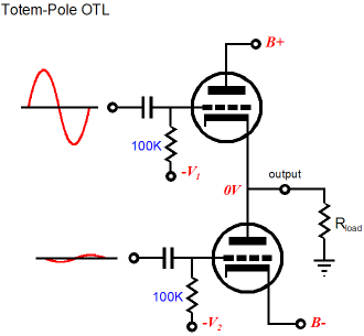
What are missing from the 1967 catalog are solid-state goodies, such as fast-slewing OpAmp, high-voltage transistor and MOSFETs, IC constant-current sources, DACs, CPUs, three-pin voltage regulators… Well, this has been a long preface for the following section, which deals with establishing balanced operation from an OTL totem-pole output stage with a differential long-tail phase splitter, as this design technique doesn't require any solid-state support.
A Different Differential Input Stage
We can use the long-tail differential phase splitter instead, as it, too, can be modified to provide the needed dissimilar drive signals. Earlier this year, in post 471, we saw how the standard differential phase splitter could be altered to provide both improved PSRR and better balanced drive signals for the top and bottom output tubes.
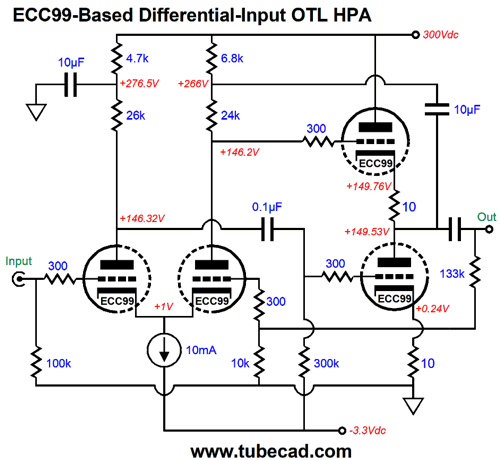
The 26k and 24k plate resistors may seem imbalanced, but this seeming discrepancy vanishes when we place 26k in parallel with 300k, which is the bottom triode's grid resistor value, and get 23.92k, only 3 thousandths off of 24k. This is a headphone amplifier, but the topology could easily be applied to a big power OTL, with many 6C33 output tubes. Remember, topology is that which stands independent from scale.
Wikipedia actual defines electronic topology quite well:
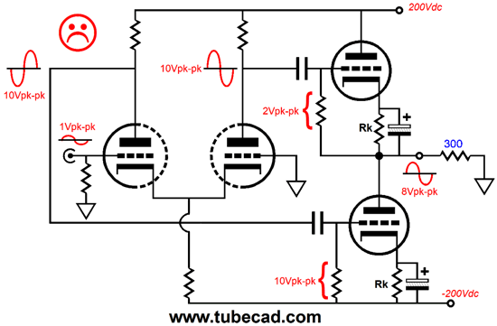
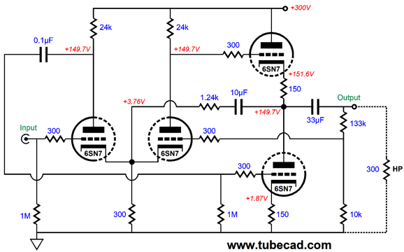
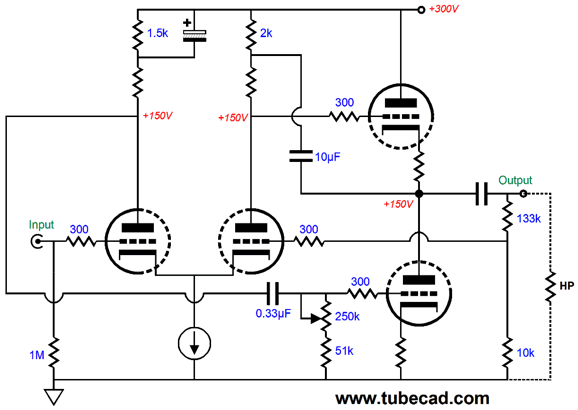
The key part in the schematic shown above is the 10µF capacitor that bridges the amplifier's output to the phase splitter, as this capacitor relays the output signal to the phase splitter, so the top output triode will see a vastly larger and exact input signal magnitude to ensure balanced operation of the output stage. Without this capacitor, the top triode would see the same magnitude of signal as the bottom output triode, which would prompt far too big of current swings from the bottom triode and too little current swings from the top triode. In other words, a balanced set of input signals would result in an unbalanced output stage operation.
Both top and bottom output tubes must see the same magnitude of input signal relative to their cathodes, not ground. Another approach was shown in post 418, where we see the differential stage's constant-current source replaced by a resistor and bridging capacitor.
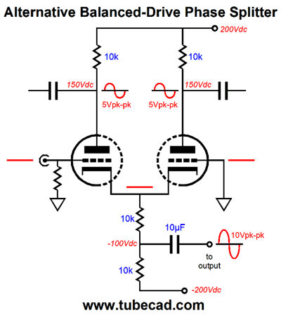
The 10µF capacitor now relays the output signal to the bottom of the differential phase splitter. In post 418, I also showed my variation that attached the signal-relaying capacitor at the top of the differential phase splitter. I vividly remember the day the inspiration hit me, as I alternated between saying to myself: BS, brilliant, BS, brilliant…
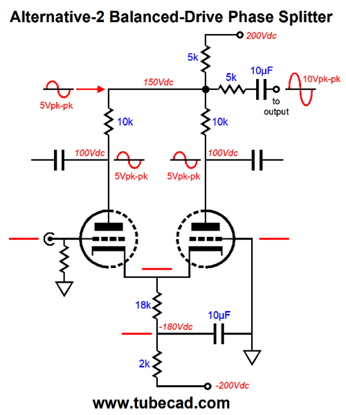
Well, what if we are not using a bipolar power supply? What if we are using a monopolar power supply? The trick then would be to place the signal-relaying capacitor and a series resistor so that the string terminated at the coupled cathodes in the differential phase splitter.
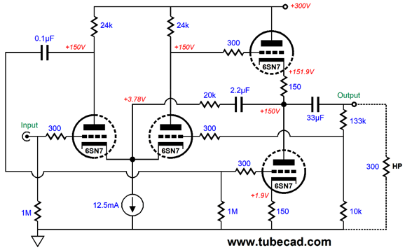
The 1.24k resistor forms a two-resistor voltage divider with the 300-ohm shared cathode resistor. The result is that balanced operation obtains between top and bottom output tubes. The downside is that the negative feedback forces us to find the optimal series resistor value with every change in negative feedback ratios. If we replace the shared cathode resistor with a constant-current source, we can use a far larger value for the series resistor.
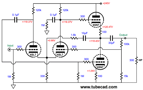
Bear in mind that the coupled cathodes follow the input signal, so the coupled cathode voltage must be high enough to support the constant-current source while the coupled cathodes bounce up and down in voltage swings. In other words, a low-mu triode should be used in the differential phase splitter. But low-mu means low negative feedback. What if want to use a high-mu dual triode, such as the 6SL7, 12AT7, 12AX7, 5751, 5691? The workaround is to return to using the shared cathode resistor in place of a CCS (or add a low-voltage negative power-supply rail).
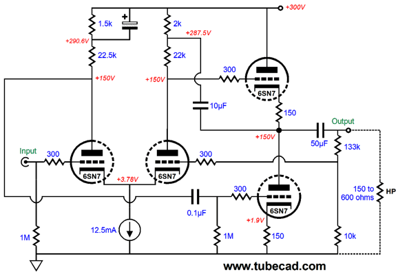
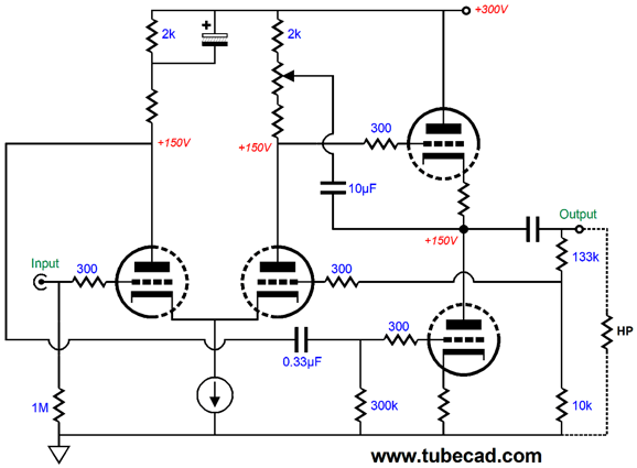
The 6SL7 offer a mu of 70 and its shared cathode voltage is only 0.66V, far too little for any solid-state constant-current source, especially when we factor in the +/-1Vpk voltage swings of the input signal. (The added 0.1µF capacitor and 1M resistor are there to restore balance and improve PSRR without shifting the DC operating points.) Here is where the year 1967 enters the picture. This circuit could have been invented in 1967… or even 1947. Is it perfect? No, but then what circuit is? It is an interesting solution to an otherwise bad situation. While evaluating the topology that returns the output signal to the top of the differential phase splitter's right plate resistor, my SPICE simulations revealed that enhanced PSRR could be had by shunting the 1.5k in the following schematic with a capacitor, rather than use the capacitor to decouple the 1.5k resistor from the B+ voltage by terminating the other end of the resistor to ground.
What is happening is that the bottom output triode must overcome the ripple that leaks through the top output triode, so the bottom triode must see more of the power-supply noise at its grid.
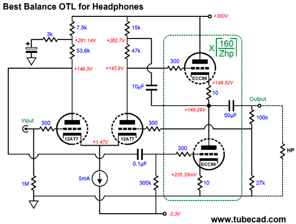
Ultimate Tube Headphone Amplifier
The 12AT7 in the differential phase splitter provides a fair amount of gain. The problem of insufficient voltage headroom at the coupled cathodes is solved by using a 3.3Vdc negative power-supply rail, which also doubles as negative grid-bias voltage for the output stage. The output stage consists of one to five ECC99 dual-triode tubes placed in parallel, so truly low headphone impedance can be driven, and driven hard. The odd looking semi-brackets are the math symbol for the ceiling function, where the closest bigger integer is found. For example, if the headphone impedance is 300 ohms, then 160/300 = 0.533 and the closest larger integer is 1. if the headphone impedance is 32 ohms, then 160/32 = 5 and the closest larger integer is 5, so five ECC99 tubes per channel would be needed. The SPICE-generated transient graph reveals the excellent balance. The output voltage swing was +/-4Vpk into 300 ohms.
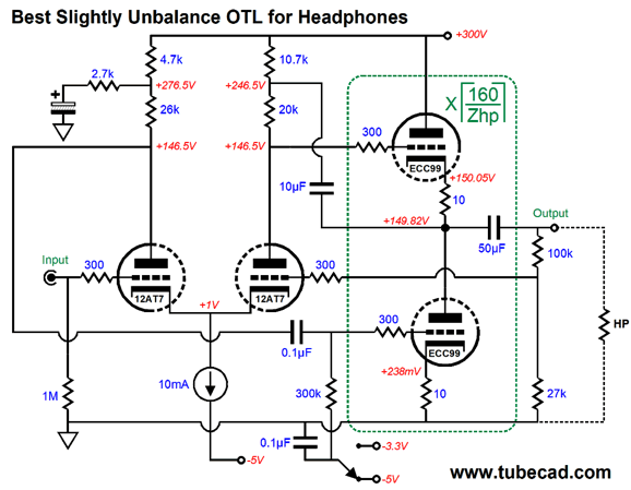
The best slightly imbalanced version looks like this.
Yes, I did sneak in some extra parts at the bottom. The toggle switch allows us to pick two idle currents for the output tubes, high and low. The get the longest life from the tubes, we choose the -5V bias voltage; to get the best sound, the -3.3V bias voltage. Okay, how did the two versions compare? In terms of THD, the best balance version easily won, but the slightly imbalanced version probably would sound better.
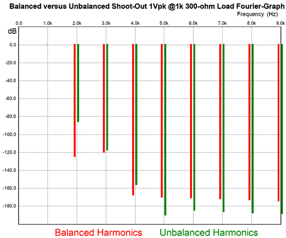
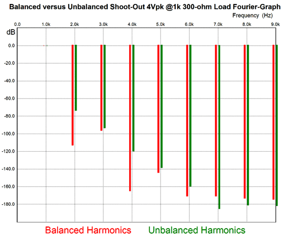
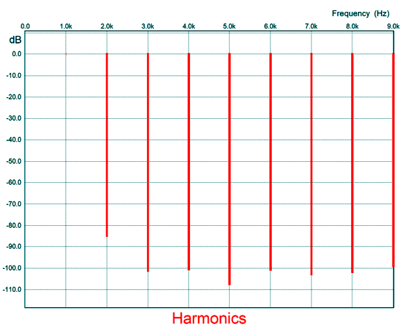
The best-balanced version's 2nd harmonic is fully -40dB down compared to the slightly imbalanced version, but note the 5th and 7th and 9th harmonics. Now, let's look at 4Vpk of output voltage swing at 1kHz.
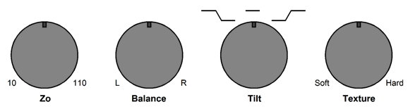
The best-balance version displays the typical push-pull harmonic structure, while the slightly-imbalanced version, in contrast, looks like a single-ended design. Okay, how do we implement a variable balance control. One easy solution is to use a potentiometer at the bottom triode. At one extreme, we get best balance; at the other, slight imbalance.
What I do not like this version, as the PSRR enhancement would also vary with the knob's rotation. A better approach would be to place the potentiometer at the top triode.
The improved PSRR still obtains. One good thing about both approaches is that no sustained DC current flows through the potentiometer's scrapper, just AC signal.
Simple MC Pre-Preamp First of all, just about every LP-loving audiophile buddy of mine who has tried an active gain stage as a pre-preamplifier for MC cartridges has returned to using a step-up transformer instead, which was something that I told him and that ended our conversation. Well, I wondered why that would be. Why did the solid-state solution ultimately fail to beat the transformer? I know that all inductive devices present their liabilities and that all high-quality audio transformers—of any kind, be they output transformers or MC step-up transformers—are hugely expensive. One thought was that the transformer sidestepped the problems that arise from power supplies and house-ground issues, but a phono cartridge is free-floating with no connection to the wall voltage. Another thought was that solid-state gain stages produced either too much noise or too brittle a sonic signature. I know that the best OpAmps offer amazingly low noise, so I assumed that the problem must lie with the sonic signature. This conclusion led me back to vacuum tubes as the possible solution. We can lower tube noise by placing many triodes in parallel.
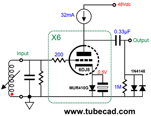
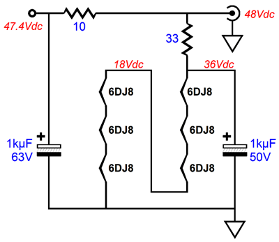
Here we see three 6DJ8 tubes used per channel, a total of six parallel triodes per channel. Six 6DJ8 triodes in parallel will be almost -8dB quieter than a single 6DJ8, which could prove decisive in a pre-preamplifier. Each triode gets its own MUR410G rectifier to establish its cathode bias, all of which could be replaced by 100-ohm resistors. The two signal diodes (1N4148) protect the following phono stage from seeing any output signal greater than 0.7Vpk. (Schottky rectifiers would offer an ever lower voltage clipping.) The 30mA constant-current source shields the triodes from the power-supply noise and allows the entire amplification factor to be realized as the output gain, which with the 6DJ8 is about 31 or +31dB. The 48Vdc power supply also powers the heater elements, as the six 6DJ8 heater element would be placed in series with a 33-ohm power resistor. In addition, the heater string should be shunted with a large-valued 50V capacitor, say 470µF/50V Panasonic FC or FM series capacitor. The power supply could be a medical-grade switcher that puts out 500mA to 1A.
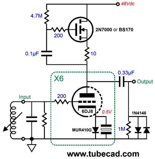
This circuit does invert the phase, so the phase should be flipped at the cartridge pins. The constant-current source could be made from either an IC regulator, such as the LM317-HV or discrete transistors. Another possibility is the following, which uses a MOSFET in a compliant-constant-current source (CCCS) configuration.
The CCCS just passes the current drawn by the six triodes, while presenting an ultra high impedance. The result of using the CCCS is high gain, far more than the 12dB requested. One workaround would be to replace the input tube in the Aikido phono stage (a 12AX7) with a 12AY7 (aka 6072) or even a 12AU7. Another possible input tube would be a 6DJ8, in both of the Aikido gain stages, which would bring to total phono preamp gain to 58dB, still more than what he wanted, but probably acceptable; this change, however, requires changing the cathode resistor values and heater element jumper wires. On the other hand, the double use of the 6DJ8 tubes would prove far quieter than the double use of 12AX7 tubes. Okay, that was my tube workaround. I then began to think about making a solid-state pre-amplifier that was more tube-like. In other words, what if we forwent the use of dual-complementary transistors, relying on single-ended amplification throughout? In addition, it would be great to use as few transistors as possible.
Two transistors and -/+12Vdc bipolar power supply and few resistors and capacitors and we are there. The circuit topology is a simple NPN-PNP compound, with the NPN transistor being in charge of the PNP transistor. The gain is 12dB, which is set by the 100- and 3330-ohm resistors. A large-valued non-polarized capacitor terminates the feedback string of resistors into ground. The coupling capacitor at the output blocks the DC from entering the following phono stage, which would upset a solid-state phono preamp that was DC-coupled at its input. What about a tube-based phono preamp? It depends, but the Aikido PH-1 or PH2 could easily function in the presence of a few millivolts of DC offset. Here is a DC-coupled version.
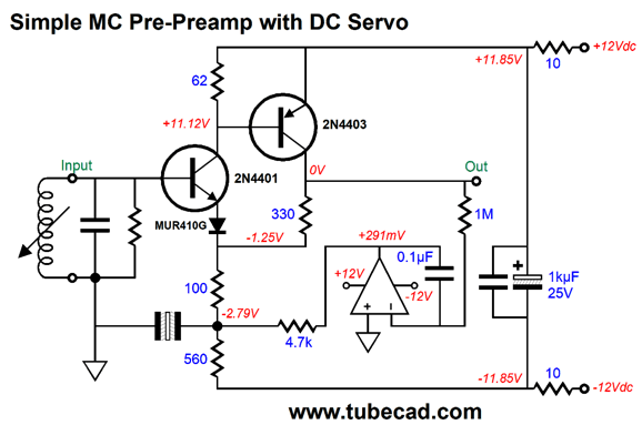
(Yes, I did sneak in a few more parts.) Placing the MUR410G in series with the 2N4401's emitter allowed us to drop the output voltage to close to zero volts. The 10-ohm resistors and 1kµF capacitor are there to post filter the -/+12V bipolar power supply, with each channel getting its own set of resistor and capacitor. One potential problem is that the transistors are very sensitive to changes in temperature, so the DC offset might drift away from 0V. One workaround is adding a DC servo circuit that would steer the output to 0V actively.
The OpAmp, which should hold a FET-based input stage such as the AD712 or LF412, varies it DC output voltage to establish a nulling of the DC offset. The OpAmps should be powered before the 10-ohm RC-filter resistors. So, how does this final circuit perform? Not bad. Here is the SPICE-generated Fourier graph.
Note the single-ended harmonic structure; furthermore, note the 3rd and 5th harmonics which are unnaturally low. The THD is better than 0.01%. This circuit is simple enough to be assembled on perf board. Unlike the six-triode pre-preamplifier, this circuit does not invert the phase.
Music Recommendation: 360 Reality Audio
In other words, Microsoft users need not apply. Microsoft and Sony have a long history of not working together; remember the video tape and DVD format wars that had the two companies in opposing camps. I always sided with Sony, as Microsoft's slogan seemed to be, "The cheapest, lowest-common denominator will make us rich far beyond the dreams of avarice."
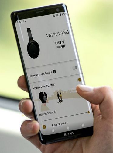
I loaded the Sony app to my Sony smart phone and used my phone to take photos of my two ears which the app then analyzed and optimized the playback of Tidal on my phone for them. In addition, the music needs to receive fancy Sony 360 encoding to make the full 360 experience happen. I own a pair of Sony ear buds, but not the right ones to take the full advantage of 360 Reality Audio experience. (This Christmas that might change for me, as the Sony WF-1000XM3 wireless noise-canceling ear buds would make a lovely stocking stuffer. My wife always faces the problem of what to get the man who has everything but common sense.) I selected a pair of Sony headphones that I thought came close to my Audioquest Nighthawk headphones. How did it sound? Interesting. The sound appeared to come as if I held the headphones off and away from my head. Nothing like 360 sound, but certainly far more spacious than usual. Here is the blurb from Sony:
Give the Sony app and the Tidal collection of 360 recordings a listen.
//JRB
User Guides for GlassWare Software
For those of you who still have old computers running Windows XP (32-bit) or any other Windows 32-bit OS, I have setup the download availability of my old old standards: Tube CAD, SE Amp CAD, and Audio Gadgets. The downloads are at the GlassWare-Yahoo store and the price is only $9.95 for each program. http://glass-ware.stores.yahoo.net/adsoffromgla.html So many have asked that I had to do it. WARNING: THESE THREE PROGRAMS WILL NOT RUN UNDER VISTA 64-Bit or WINDOWS 7 & 8 or any other 64-bit OS. I do plan on remaking all of these programs into 64-bit versions, but it will be a huge ordeal, as programming requires vast chunks of noise-free time, something very rare with children running about. Ideally, I would love to come out with versions that run on iPads and Android-OS tablets.
//JRB
|
|
John Gives
Special Thanks to the Special 84 To all my patrons, all 84 of them, thank you all again. I want to especially thank
I am truly stunned and appreciative of their support. In addition I want to thank the following patrons:
All of your support makes a big difference. I would love to arrive at the point where creating my posts was my top priority of the day, not something that I have to steal time from other obligations to do. The more support I get, the higher up these posts move up in deserving attention. Only those who have produced a technical white paper or written an article on electronics know just how much time and effort is required to produce one of my posts, as novel circuits must be created, SPICE simulations must be run, schematics must be drawn, and thousands of words must be written. If you have been reading my posts, you know that my lifetime goal is reaching post 1,000. I have 518 more to go. My second goal is to gather 1,000 patrons. I have 916 patrons to go. Help me get there.
Only $12.95 TCJ My-Stock DB
Version 2 Improvements *User definable Download for www.glass-ware.com |
||


| www.tubecad.com Copyright © 1999-2019 GlassWare All Rights Reserved |