| John Broskie's Guide to Tube Circuit Analysis & Design |
19 April 2020 Post Number 501
I Measure Time in Albums
More Upside-Down Cascode Circuits
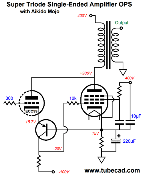
The pentode is enslaved by the triode, as the triode imposes its electrical fingerprint on the pentode. How so? The ECC99 triode's plate terminates into the pentode's plate; and this connection effectively becomes a negative feedback loop. Here is an example: we apply +1V to the ECC99's grid, which increases its current conduction, which in turn increases the voltage drop across the collector resistor, forcing the pentode's grid to experience a huge positive voltage increase, prompting a proportionally big current flow increase that will pull both plates down in voltage. By how much? The answer depends on the triode's amplification factor (mu), which for the ECC99 is 22, so by -22Vpk. At the risk of annoying some, I will repeat just what a triode's amplification factor is; it is a measure of the grid's relative effectiveness in controlling the current flow through the triode compared to the plate's ability to control the current flow. Thus, a mu of 22 means that the grid is 22 times more effective than the plate, when it comes to controlling the triode's current flow. mu = gm · rp gm = mu/rp rp = mu/gm Another way to examine this output stage is to imagine forcing the two tied plates' voltage raised by 1V due to an externally applied voltage pulse. On its own, the pentode is fairly indifferent to the tiny increase in plate voltage, as its plate impedance is so vastly high. In contrast, the triode's plate resistance is fairly low, with an ECC99's coming in at about 2300 ohms. Thus, we can expect the ECC99's current conduction to increase by 1/2300 or 0.435mA. Not that much, admittedly. But this increase in current also flows through the PNP transistor into the collector resistor, say a 16k resistor, which will create +7Vpk increase in the pentode's grid voltage. Let's assume that the pentode's transconductance is 10mA/V, so its current conduction will increase by 70mA. Considering that the pentode might have idled at 100mA, the 70mA increase is huge. In fact, it implies an effective plate resistance of 14.3 ohms, which is 161 times lower than a single ECC99. And when the output transformer translates this effective impedance at its secondary, we will have an astoundingly low output impedance. How low? Say the primary impedance is 2400 ohms and the loudspeaker is 8 ohms, this implies an impedance ratio of 300:1, so the 14.3 ohms must be divided by 300. Dang low, in other words. Missing from the schematic was the rest of the amplifier. Not much is needed to fill out the design. We could use the other ECC99 triode as the input stage, a simple grounded-cathode amplifier, which need only provide a gain of 11 to drive the output stage to full output with 1Vpk of input signal.
Aikido mojo enters the output stage through the 10µF capacitor that bridges the B+ voltage to the pentode's cathode and the transistor's base. With the 220µF capacitor, the 10µF capacitor will leak 1/23 of the AC ripple to the top of the cathode resistor. Why? We want the triode and pentode to ignore entirely all the power-supply noise. If they didn't, the output stage's amazingly low output impedance would result in almost all the power-supply noise to superimpose across the primary, which the loudspeaker would then see at the secondary. In other words, a pitiable PSRR, approaching none whatsoever. However, if the two tubes maintain a current flow oblivious to the power-supply noise, the primary will be blind to the noise and your ears will be deaf to it as well. One interesting feature to this output stage design is that pentode auto-biases nicely, due to the triode controlling the pentode. If the pentode draws too much current, the transistor's base will see the increase in voltage drop across the cathode resistor and the ECC99's cathode voltage will also rise, thereby forcing a reduction in the triode's current, which in turn will cause a decrease in the voltage drop across the collector resistor, forcing the pentode's grid voltage to drop. In other words, a simple DC negative feedback loop. The 10µF and 220µF capacitors are effectively in parallel as far as the cathode resistor is concerned. Assuming a 150-ohm cathode resistor, the capacitors shunting will extend down to about 5Hz.
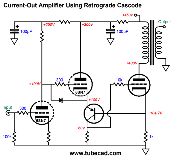
Current-Output Single-Ended Output Stage
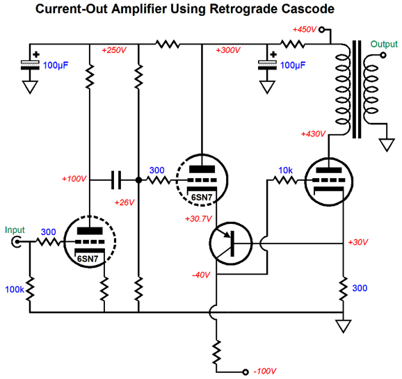
I purposely made the amplifier DC coupled internally to prevent conceptual clutter—always a good goal. If the output triode's plate terminated into the B+ voltage, rather than the output transformer's primary as shown, the circuit would be a high-performance cathode follower, with the output taken from the output triode's cathode. If we force the output tube's plate up by 1V, the output triode's would normally rise as a result, but not in this circuit, as any unexpected increase in transistor's base voltage will be countered by the triode that sits above it. The tiny increase in base voltage will be relayed to the triode's cathode, forcing a reduction in the triode's current conduction, which in turn will create a big negative voltage swing at the output tube's grid, forcing the output tube to maintain its idle current as if the positive voltage pulse didn't exist. In other words, the output tube's output impedance will seek to approach infinity. Okay, let's now see a more realistic design, one that uses an internal coupling capacitor.
The output tube's cathode voltage has been reduced to only 30Vdc and a negative power-supply rail voltage was added. A voltage drop of 30V across the 300-ohms cathode resistor implies an idle current flow of 100mA for the output tube, which against a 2.4k primary impedance further implies an output power of 12W. How so? We use the formula Power = I² × Rload/2 Thus, 0.1² times 2400/2 equals 12 watts. Perhaps, we might actually come close to realizing it, but don't bet on it . Remember, the output tube's cathode resistor is not shunted by a large-valued capacitor; instead, this resistor must see current swings from 0A to 200mA. When the output triode experiences its peak current draw, its plate voltage will fall by 240V and its cathode voltage will rise by 30V, making a 270V reduction of the idle cathode-to-plate voltage of 400V, leaving only 130V, which would not be enough for a 300B output tube to support without entering positive grid voltage territory, which this circuit does not allow, as the PNP transistor imposes a strict limit on positive grid-to-cathode voltages. See post 498 for more information on single-ended output stage limitations and losses. If we are going to get full output from this design, the output tube's cathode resistor must see its idle current double. In this example, it must go from 100mA and 30V to 200mA and 60V. In other words, a +/-30Vpk voltage swing, which implies a signal gain of 30. The driver triode, a 6SN7, delivers no closed-loop signal gain; and the input triode, also a 6SN7, cannot deliver a gain much above 15 or so. Even with a constant-current source plate load, its maximum gain would equal its amplification factor, i.e. 20, not enough for 1Vpk of input signal. The easy workaround would be to use a higher-mu input triode, such as the 6SL7. We could replace the output triode with an output pentode. I showed the triode in this schematic to make the point that the output impedance would prove high in spite of the triode's use. The internal coupling capacitor and the two-resistor voltage divider resistors that set the driver 6SN7's grid DC voltage also work to set the output tube's idle current. Here is we can add a potentiometer to adjust the output stage idle current. As the 6SN7's grid voltage rises, so, too, will its cathode voltage, which will force the output tube's cathode voltage to also follow. By the way, if the 6SN7 is missing from its socket or yet to warm up, the output tube will see a grid voltage equal to the negative power-supply rail voltage; in this example, -100V. This is a great place to start at turn-on, as the output stage idle current will come up slowly. No doubt, some of you are wondering why we cannot replace the collector resistor with a constant-current source, as that would vastly increase the open-loop gain of the retrograde cascode. We could, but we risk instability. One workaround is to add a small capacitor from the output tube's cathode to the collector, which will limit the high-frequency bandwidth and prevent excessive phase shift. No mention has been made about PSRR or Aikido mojo enhancements. None is needed. The current-out design automatically enjoys a fine PSRR figure, as the B+ voltage ripple does not prompt any change in the output tube's current flow.
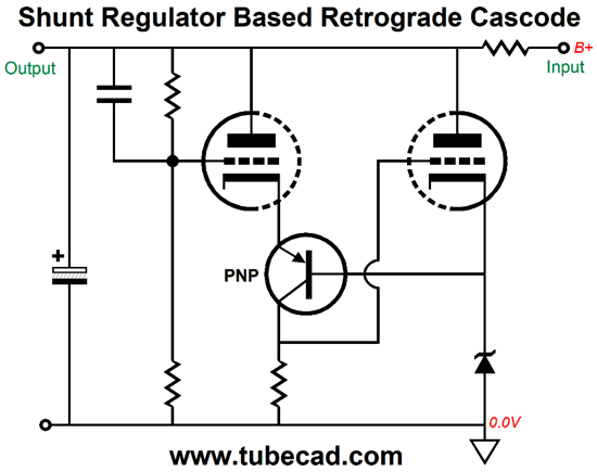
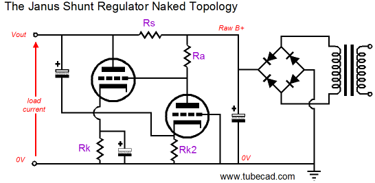
Shunt-Regulator Based on the Retrograde Cascode In nutshell, the shunt regulator is analogous to the single-ended output stage, as it must run in a form of glass-A operation. In contrast, the series voltage regulator is more like half of a class-B push-pull output stage. If the target audio circuit draws a peak variation of 20mA, then the shunt regulator's pass device must idle at least at 20mA; whereas, a series regulator's pass device can idle at whatever the powered circuit's idle current is, say 5mA, and then allow the increase flow of 20mA or more. In other words, the series regulator only delivers extra current when it's needed, while the shunt regulator must be designed to deal with the expected peak current flow. Series regulator functions most efficiently when the load current is low at idle and then vastly higher at peak demands. A good example of a wide current variation circuit would be a class-AB push-pull output stage, say an OTL amplifier's output tubes. In contrast, the shunt regulator works best with a fairly constant-current-draw load, such as a single-ended output stage or a CCDA circuit, as it must only deal with the small variation in current flow. A series regulator's pass device runs cool when the load current demand is least and runs hot when the current demand is at its highest. A shunt regulator's pass device runs hottest when the current demand is least and runs cool when the current demand is at its highest. Okay, enough overview. Here is a simple shunt regulator based on the retrograde cascode topology.
All voltage regulators require three things: a voltage reference, a pass device, and a form of negative feedback. In this design, the zener diode is the voltage reference; the triode on the right, the pass device; the left triode and PNP transistor, the negative feedback mechanism. The left triode's grid sees 100% of the output noise, but only a percentage of the output DC voltage due to the two-resistor voltage divider. The ratio between the two resistors and the zener voltage set the output DC voltage. If the output voltage climbs too high, the left triode will see its grid rise in voltage, which will prompt the triode's current flow to increase, causing the voltage drop across the collector resistor to rise substantially, forcing the right triode's current conduction rise appreciably, thereby pulling down the output voltage until it falls in line with the target voltage. Okay, lest flesh out the design with some example part values.
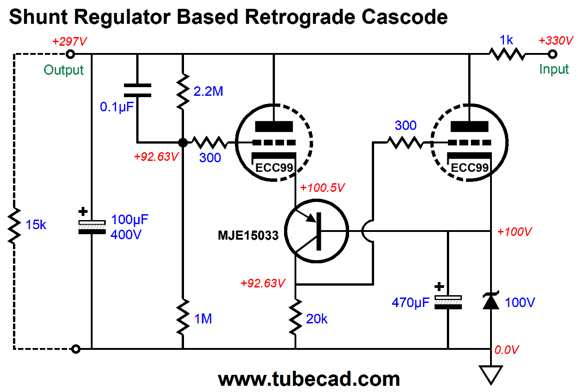
The ECC99 high wattage and high-current delivery make the tube a good choice for this task. The MJE15033 PNP transistor is a 250V, 8A, 50W transistor in a TO-220AB package; in addition, the transistor exhibits a flat current gain up to 1A and current-gain/bandwidth-product (fT) of 30MHz. The external load, represented here by the 15k resistor, draws 20mA of current. The 1k series resistor implies a current limit of 30mA, with the 300V output voltage. On the other hand, with an output voltage of 250V, the current limit rises to 80mA. By the way, we must always factor in wall-voltage variations. For example, if the wall voltage falls by 10% of its target voltage, this shunt regulator will be voltage starved, as the B+ voltage will fall by 33V, which is below the target output voltage. At the other extreme, if the wall voltage climbs up 10%, the raw B+ voltage will rise to 363Vdc, which means that the 1k resistor's dissipation will quadruple, as it will experience twice the voltage drop. Okay, let's now add a few extra bells and whistles.
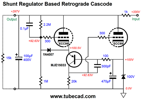
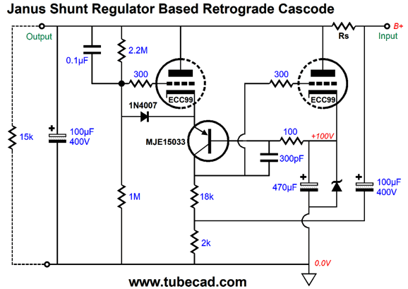
The added diode is there to protect the left triode at turn-on, as the o.1µF charges up slowly due to the 1M resistor. The added 100-ohm resistor and 300pF capacitor are there to prevent high-frequency issues from arising. If we wish to get extra fancy, we can perform a Janus transformation. As the regulator circuit stands, the regulator reacts to changes in the output voltage, which can be caused by signal-induced current variations or by raw power supply ripple. The Janus regulator, in contrast, looks both forward to the output voltage and backwards to the ripple on the other side of the series resistor.
To turn the retrograde shunt regulator into a Janus regulator requires the right triode's current conduction to anticipate raw power supply ripple and vary its flow to create a null at the output. The first step is to return the power-supply noise to the right triode's grid.
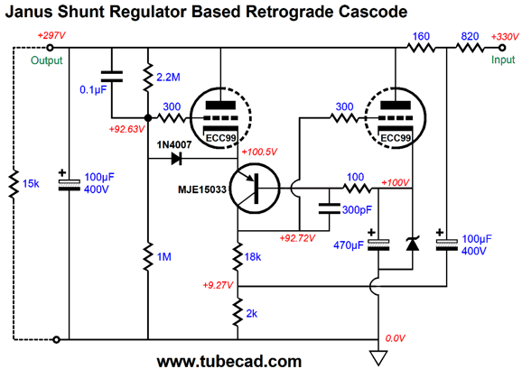
The 100µF capacitor couples the raw power supply ripple to the top of the 2k resistor and, by extension, to the top of the 18k collector resistor. This setup works due to the high output impedance presented by the collector. The next step is to use a series resistor equal to the inverse of the right triode's transconductance, which in the case of the ECC99 is about 0.0095A/V. Thus, the required series resistor would be 105 ohms. This is a relatively low value, so we add a 910-ohm resistor in series with it. Well, that was the theory. In SPICE simulations, however, the optimal values are shown below. What went wrong with the theory? A triode's transconductance is not constant across plate voltages and cathode currents. In addition, the transistor's collector's impedance isn't actually infinity due to the Early effect.
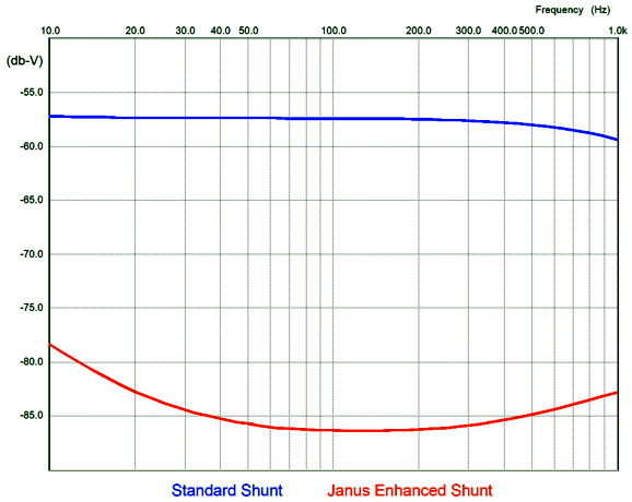
The important part value is the 160-ohm series resistor, as it complements the ECC99; use a different triode, then use must use a different resistor value. The 820-ohm series resistor is not so constrained, as we can use whatever value is needed to fill in the desired voltage drop and current flow. THe Janus modification results in a huge increase in PSRR, which went from –57dB to –86dB, which was easy to test, as I only had to delete the extra capacitor and run the test again. Here is the PSRR graph that shows how much of the raw power-supply ripple is attenuated.
So what's not to like here? The ECC99's heater element draws far more current than the 12DW7/ECC832 that the Janus regulator uses. In addition, the ECC99 heaters need to be referenced to between 100Vdc to 150Vdc. Moreover, all shunt regulators require more thought than a series regulator, which helps explain why they are not more common. Nonetheless, this looks like a promising design. (If only I owned or worked at a PCB fabrication firm, I would rip out a PCB for this design in a flash.)
DHT Heating Power Supplies
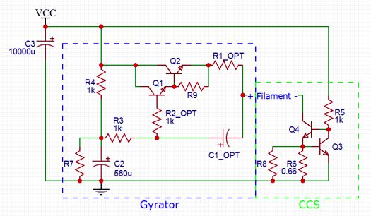
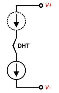
It looks complicated, but the conceptual schematic is simple.
One aspect of any constant-current source approach to heating either heater elements or DHT filaments is that the tube will last longer and suffer fewer open heater elements, as the constant-current source sets a limit to the current flow. In contrast, a fixed voltage regulator or simple AC winding will prompt a huge current-inrush, as a cold heater element or filament presents a far lower resistance than it will when hot. For example, when hot, a 2A3's filament presents 1 ohm of resistance; cold, only 0.3 ohms. Unfortunately, we run into a problem: tubes vary; for example, not all 300B tubes draw the same current with a 5V voltage drop across their filament. In other words, some means of adjusting the current will be needed, along with a voltage meter. Okay, so what do I think about the Coleman design? It seems to fail its major design goal, namely situating the filament between high-impedance paths to the floating power supply. How so? If we examine the schematic, we see the following setup.
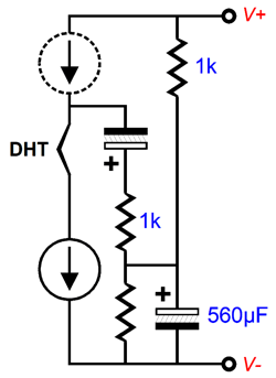
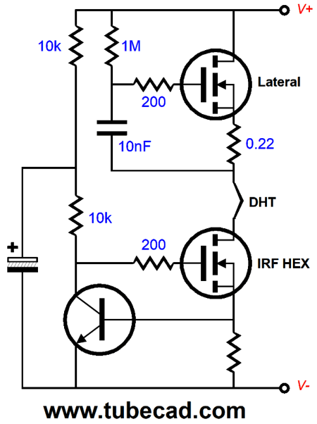
At audio frequencies, the filament sees a 1k path to the negative power-supply rail and 2k path to the positive power-supply rail. If a lateral MOSFET had been used above the filament, rather than the Darlington transistors, much larger resistor values could be used, along with a much smaller capacitor value. Sadly, this type of MOSFET is neither cheap nor readily available.
Okay, let's put on our thinking caps and devise some alternatives. One thought that immediately comes to mind is the possible use of a choke. An ideal inductor displaces not DC voltage and dissipates no heat, unlike transistors or MOSFETs.
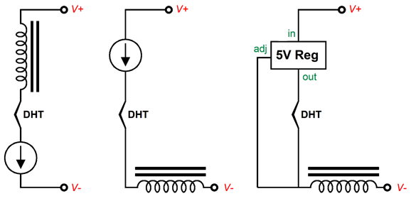
Reading from left to right, the first two circuits use a constant-current source and choke to isolate the filament from the external floating power supply. The last circuit uses a fixed-5V LDO voltage regulator also shields the filament from the positive power-supply connection, as the regulator and filament define a constant-current source, with the filament resistance replacing the usual resistor. In all these circuits, I would shunt the filament with a large-valued capacitor, say 10kµF. Another type of inductor we could use is the common-mode choke.
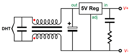
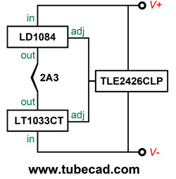
This dual-winding inductor freely passes the DC current, but bucks high-frequency hash. One danger with the previous choke designs is that chokes can function as hum magnets, if not carefully oriented in relation to the power transformers. The common-mode choke is far less sensitive. Okay, let's now get extra fancy. What if we use two voltage regulators, a positive and a negative regulator, in a vice-grip arrangement with the filament, so the filament sits between both regulator outputs? How will the regulators be voltage referenced? A good question. Here is one possible solution.
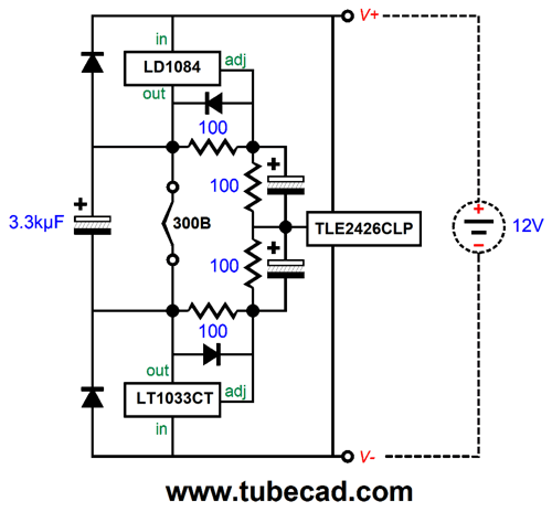
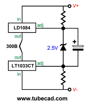
The TLE2426CLP is a rail-splitting IC made by Texas Instruments. It creates a virtual ground and bipolar power supply out of a monopolar power supply. Both voltage regulators are the adjustable types that hold an internal 1.25V voltage reference and will put 1.25V volts with a ground adjustment pin. What if you own 300Bs, not 2A3s?
It’s a tad more complicated, but not too much so. We still use the two regulators and the rail-splitter IC. What we add are many resistors, diodes, and capacitors. This design also self-centers and slowly ramps up to the 5V output voltage. I show a 12V floating power supply, but I bet it would work with just 10V. Build and test is the best procedure here. Another possible setup is the following.
By the way, remember that each DHT output tube requires its own floating power supply in most amplifier designs.Speaking of the floating power supply and its needed DC voltage, a better approach might be the following design.
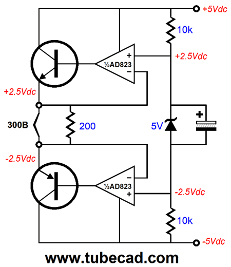
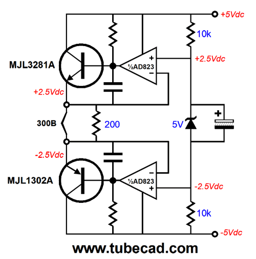
The AD823 is an interesting dual OpAmp that can swing from rail to rail, due to its FET input stage and common-emitter output stage, rather than the usual emitter follower. It also works over a crazy wide differential power-supply voltage, from 3V to 36V. Each OpAmp gets its own power transistor to control. The 5V zener (or voltage-reference IC) is shunted by a large-valued capacitor to create a slow ramp up of output voltages. This design auto centers and works with a floating power-supply voltage of only 8V. Here is more deluxe version, with added pull-up resistors and stability capacitors.
Where this design will run into trouble is with higher output currents. For example, an 845 triode's thoriated tungsten filament is powered with 3.25A at 10V. For such demanding loads, we need to switch to a different topology.
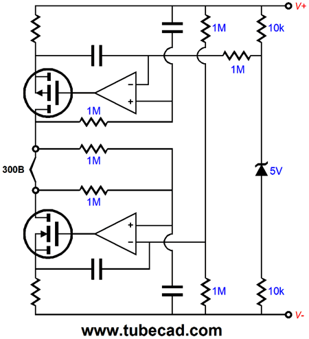
What I have created here is two compliant-constant-current sources that auto-center and maintain a fixed voltage across the filament.
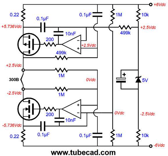
The top OpAmp and P-channel MOSFET set the voltage drop across the filament. The bottom OpAmp and N-channel MOSFET auto center the filament inside the voltage window imposed by the external floating power supply. The source resistors are relatively low-valued, as they only need to drop a fraction of a volt. (If only I were a patent attorney.) Okay, lets' flesh-out this design with workable part values.
The capacitor shunting the 5V voltage reference makes for a slow turn-on and quells whatever noise the zener creates. The 10nF capacitors are there to ensure that the AD823 doesn't run into high-frequency problems. The bottom OpAmp effectively sees each pair of its 1M resistors in parallel, which explains why the top OpAmp gets 499k resistor, rather than 1M resistors. This allows us to use 0.1µF capacitors throughout. In SPICE simulations, I used the IRFP240 and IRFP9240 MOSFETs. (Once again, if only I owned or worked at a PCB fabrication firm, I would rip out a PCB for this design in a flash.) For many, OpAmps are a no-no. Well, we can go full discrete.
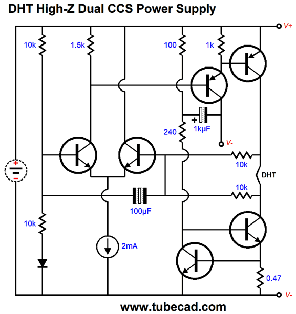
The idea here, much like the previous MOSFET-based design, is that we have dual constant-current sources with a DHT filament in between. The differential stage based on the two 2N4401 NPN transistors works to center the filament within the optimal voltage window. Here is the fleshed out circuit.
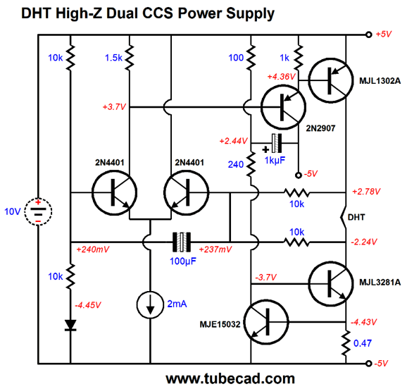
The MJE15032 transistor monitors the voltage drop across the 0.47 ohm emitter resistor. In other words, the transistor controls the MJL3281A'd current flow. The CCS could be made from two NPN transistors or we could use an LM334. Since the LM334 looks like a transistor, it might fly under the radar of the IC hater.
The circuit works with a floating power supply voltage between 8Vdc to 10Vdc. Once again, the problem with all forms of heating the filament by a constant-current source is that the current must be adjusted to yield the required voltage drop, as the tubes differ from each other and, often enough, from their published specs.
If you are getting the idea that given enough time, paper, pencil, and beer, I could come up with another 20 DHT power circuits, you are not far from right. Actually, in all honesty, I wonder if any of these trips are really necessary, as I have gotten many favorable comments for those who have bought my LV-Regulator kits for use powering their filaments in 2A3 and 300B power amplifiers.
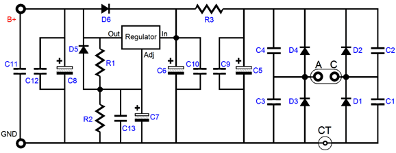
The regulator holds an RC pre-filter (R3 & C6) that scrubs away much of the rectifier hash and ripple before the LDO regulator starts to work at maintaining a fixed DC output voltage, which is why I refer to it as an audio-grade regulator. In addition, the output is shunted with a large polypropylene capacitor (C11) and a 1kµF Panasonic FM series capacitor (C8).
Music Recommendation: Easy to Remember
//JRB
User Guides for GlassWare Software
For those of you who still have old computers running Windows XP (32-bit) or any other Windows 32-bit OS, I have setup the download availability of my old old standards: Tube CAD, SE Amp CAD, and Audio Gadgets. The downloads are at the GlassWare-Yahoo store and the price is only $9.95 for each program. http://glass-ware.stores.yahoo.net/adsoffromgla.html So many have asked that I had to do it. WARNING: THESE THREE PROGRAMS WILL NOT RUN UNDER VISTA 64-Bit or WINDOWS 7 & 8 or any other 64-bit OS. I do plan on remaking all of these programs into 64-bit versions, but it will be a huge ordeal, as programming requires vast chunks of noise-free time, something very rare with children running about. Ideally, I would love to come out with versions that run on iPads and Android-OS tablets.
|
I know that some readers wish to avoid Patreon, so here is a PayPal donate button instead. Thanks. John Broskie
John Gives
Special Thanks to the Special 83
I am truly stunned and appreciative of their support. In addition I want to thank the following patrons:
All of your support makes a big difference. I would love to arrive at the point where creating my posts was my top priority of the day, not something that I have to steal time from other obligations to do. The more support I get, the higher up these posts move up in deserving attention.
If you have been reading my posts, you know that my lifetime goal is reaching post number one thousand. I have 502 more to go. My second goal is to gather 100 patrons. I have 176 patrons to go. Help me get there.
Only $9.95
The Tube CAD Journal's first companion program, TCJ Filter Design lets you design a filter or crossover (passive, OpAmp or tube) without having to check out thick textbooks from the library and without having to breakout the scientific calculator. This program's goal is to provide a quick and easy display not only of the frequency response, but also of the resistor and capacitor values for a passive and active filters and crossovers. TCJ Filter Design is easy to use, but not lightweight, holding over 60 different filter topologies and up to four filter alignments: While the program's main concern is active filters, solid-state and tube, it also does passive filters. In fact, it can be used to calculate passive crossovers for use with speakers by entering 8 ohms as the terminating resistance. Click on the image below to see the full screen capture.
Tube crossovers are a major part of this program; both buffered and un-buffered tube based filters along with mono-polar and bipolar power supply topologies are covered. Available on a CD-ROM and a downloadable version (4 Megabytes). Download or CD ROM
|
|||


| www.tubecad.com Copyright © 1999-2020 GlassWare All Rights Reserved |