| John Broskie's Guide to Tube Circuit Analysis & Design |
|
08 December 2020 Post 522
One giant step for me, but one small step for NASA*
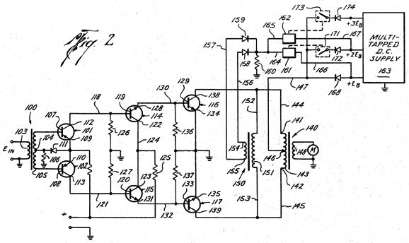
The use of the second output transformer was a brilliant move, as its primary only saw the plate-to-plate voltage swings, not the plate voltage swings relative to ground. Relative to ground, the scope traces of the plate voltages would look crazy, due to the stepped increases in B+ voltage. In contrast, relative to the plates, the sinewaves developed looked like sinvewaves. As I looked the patent schematic over, the first thought I had was,
Yes, it performs an amazing job of tracking the plate-to-plate voltage swings and isolating its secondary from its primary, but good output transformers are hard enough to find these days. My second thought was,
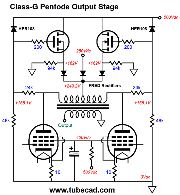
Obviously, I would have kept these two questions to myself, if I thought the answers to both were no. One idea that came to mind was that of attaching the class-G control circuitry to some preexisting part of a push-pull power amplifier, such as the split-load phase splitter.
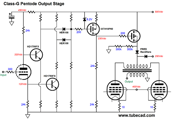
The high-voltage NPN transistors tag along with the phase splitter's two outputs. Both transistors never turn off, and they work in current anti-phase. The two HER108 super-fast diodes only become forward biased when a trip voltage is reached, which means that at idle both diodes are reversed biased and do not conduct. In addition, at idle, the high-voltage P-MOSFET, IXTH10P60, conducts a steady current that creates a voltage drop across the two 300k drain resistors that is below the 250Vdc lower power-supply rail voltage, so the only current flow through the high-voltage N-MOSFET is through the two 300k source resistors, i.e. very little. As the drive signals to the push-pull output stage grow, the HER108 diode trip voltage eventually are reached, which pulls down the P-MOSFET's gate, provoking an increased current flow from the MOSFET, which in turn forces a larger voltage drop across the two 24k drain resistors, creating a rectified AC signal for the N-MOSFET, which traces the absolute value of the plate voltage swings.
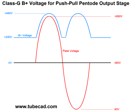
Remember that as one output pentode sees it speaker voltage drop, the other sees its plate voltage rise. In order to allow bigger plate voltage swings from the output tubes, the B+ voltage must climb for both output tubes, as they share the same connection to the B+ voltage. As the output stage nears full power output, the B+ voltage will climb closer to the 500Vdc power-supply rail voltage. Once the N-MOSFET's source voltage exceeds the 250Vdc rail voltage (plus the FRED rectifier voltage drop, say 1.2V), the output stage sees the B+ voltage decouple from the 250Vdc power-supply rail and climb with the plate-voltage swings. At all times, the output pentode screen voltage remains fixed at 400Vdc.
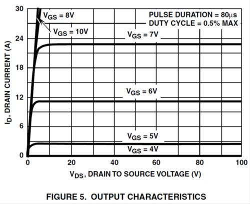
Speaking of pentodes, the output tubes should be pentodes, not triodes, as the triode's low plate resistance makes it sensitive to its plate voltage, whereas the pentode is largely indifferent to it. In other words, we want to avoid running into a glitch as the B+ voltage breaks away from its idle voltage. Note the weasel word: "largely." A pentode's plate does present some plate resistance, just far more than a triode. But how much? For example, the KT88's plate resistance is about 16k, while that of a 300B is closer to 800 ohms, 20 times lower. In contrast, an N-channel MOSFET exhibits a ruler-flat current-draw line with increasing source-to-drain voltage, which implies a vastly higher drain resistance.
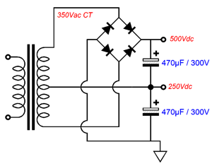
Our choice of running pentodes, however, does mean that a negative feedback loop is essential, both to lower the output impedance and the distortion. What would the power supply look like for a transformer-coupled, push-pull, class-G amplifier? Here is one possible arrangement.
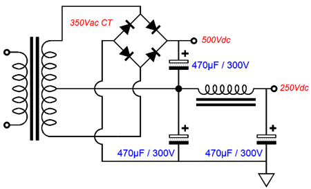
The power transformer's center-tap DOES NOT attach to ground, as it would in most tube-based power amplifiers, but to the center of the two power-supply reservoir capacitors, i.e. the 250Vdc power-supply rail. We could get much fancier, if we wished. For example, we could use either an RC or LC filter on the 250Vdc power-supply rail, but not on the 500Vdc rail, as the N-MOSFET will act as voltage regulator of sorts, as it will shield the B+ voltage from the power-supply noise, due to the two 24k drain resistors string terminating into ground and the P-MOSFET's drain presenting such a high output impedance.
Another possible arrangement would be to let the output transformer's primary drive the class-G control. One danger we want to avoid is dragging down the primary with excessive load resistance. Fortunately, MOSFETs, unlike bipolar transistors, do not require much in way of current to drive their gates. (At low frequencies this is true, but at ultra-high-frequencies, their high input capacitance does require current to charge and to discharge the capacitance.)
Two high-voltage MOSFETs are used, which simplifies the rectification circuitry. In addition, the two MOSFET instantly double the power rating, as each will only dissipate half of what one would.
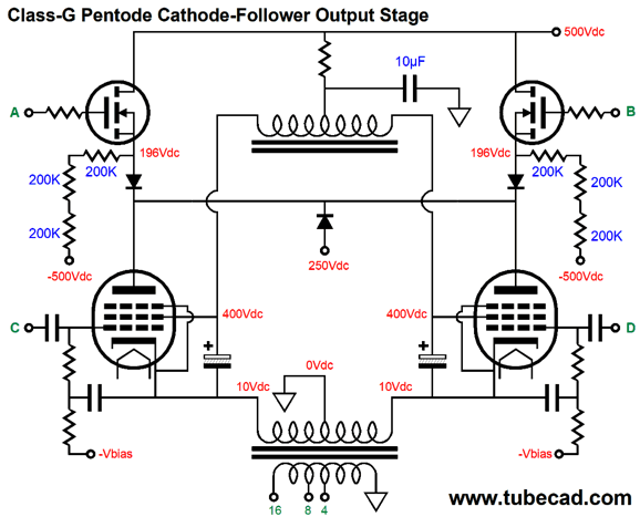
Class-G Cathode Follower OPS
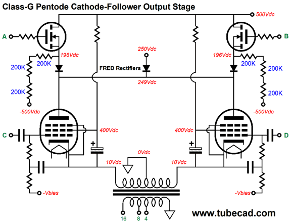
Well, we could use a portion of this huge balanced drive signal to drive the two high-voltage class-G MOSFETs. Here is a cathode follower output stage arranged for class-G amplifier operation.
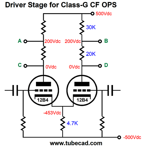
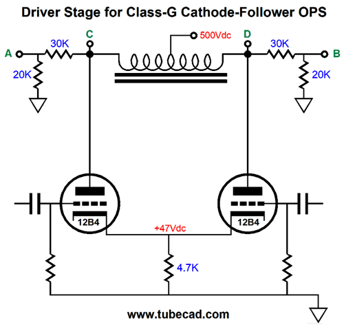
Next, we see the driver stage.
The four output signals connect to their matching letter on the output stage. At idle and low power output, the output stage runs exclusively off the 250Vdc power-supply rail. Once the drive signal reaches the trip voltage of 250V, the MOSFETs alternately engage their FRED rectifier and pull the pentode's B+ voltage up. A +/-500Vdc bipolar power supply is required, which is a hassle, as the 12B4 driver tubes will need a heater winding referenced to the negative power-supply rail. If we load the driver stage with center-tapped inductor, however, we could get away with using a 500Vdc monopolar power supply (not including the negative power supply needed for the output tube grid bias voltage).
The inductive loading allows the driver stage produce the needed +/-400Vpk balanced output to the drive the output stage. The only problem is that power-supply chokes offer too limited a bandwidth to be used here. In other words, the center-tapped inductor must be audio-grade. The workaround might be to use a low-power output transformer's primary as a center-tapped inductor. For a pentode to be used as a pentode, its cathode-to-screen voltage must be fixed, which the screen capacitors help do in the schematic shown earlier. Note, however, that these capacitors also couple the screen resistors to the cathodes in AC terms. In other words, the cathodes get the extra burden of having to drive these resistors, whic is not the case with the output transformer attaching to the plates. We can, however, replace the two resistors with a center-tapped inductor.
A single voltage-dropping resistor is used, but it sees a relatively fixed voltage drop. I am inclined to believe that we could get away with using a power-supply choke in this application, as the screen capacitors will present such a low-impedance termination. Of course, reality will perform the ultimate test. The point to this exercise is not efficiency. If we want efficiency, we would buy a class-D amplifier. No, the aim is to prolong tube life and increase peak output power. A KT88 idling under a 250Vdc B+ voltage and running an idle current of 70mA only dissipates 17.5W; under a 500Vdc B+ voltage, 35W. If we halve the dissipation, we more than double the life span.
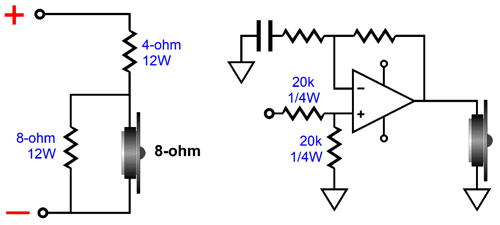
The Future of Loudspeakers and Amplification In addition, frequency tailoring is easy with active filters and DSP. Moreover, if a two-way loudspeaker held two 100W amplifiers, there is no need to worry about matching the two driver's efficiencies, as we could easily use two 1/4W resistors to pad the signal going to the tweeter amplifier. This is huge. Compare the situation with a passive loudspeaker that holds a woofer that delivers an SPL of 88dB with 2.828Vrms, while the tweeter puts out 94dB. The tweeter's output must be reduce by -6dB, which requires a padding circuit that hold two high-wattage resistors, 4-ohm and 8-ohm resistors. These resistors effectively quarters the power amplifier's output, as the tweeter only sees half of the potential amplifier voltage swing. In contrast, an active loudspeaker would pad the tweeter amplifier's input signal, halving it, while allowing the full power output to the tweeter.
Sure, I would want to listen to this sort of class-D amplifier fullrange, but from 20Hz to 2kHz I wouldn't complain. Let's be conservative and limit the class-D amplifier to the decade between 20Hz and 200Hz, which would leave 200Hz and up for tube or high-end solid-state amplification. By shifting the low-frequency cutoff up to 200Hz from 20Hz, we greatly unload the output transformer.
I have mentioned this many times before, but it's worth repeating. Long ago, I was in an electronics surplus store in Silicon Valley, where I grew up. I picked up a small, potted, power transformer and marveled at the 400VA rating. As I saw it, the transformer would be hard pressed to deliver 40VA. The label revealed the answer: the power transformer was for aircraft use at 400Hz, not 60Hz. With an input AC frequency of 400Hz, the 400VA rating was easily met. Well, if the tube-based power amplifier's output transformer only has to go down to 200Hz or so, it can also be much, much smaller. In other words, a 100W tube amplifier might sport four big output tubes and yet use an output transformer that looks as if it could only deliver 10W. Ideally, the output transformer's construction would include thicker wire and higher-quality core iron; perhaps, built-in heatsinks attaching to the bell caps would be needed. Okay, John, that's great for tube-based amplifiers with output transformers, but what about OTL and solid-state power amplifiers? A Futterman type OTL power amplifier that only had to go down to 200Hz would need only one tenth the output coupling capacitor value and that smaller capacitor could be much higher in quality as a result; think film versus electrolytic. Paradoxically enough, solid-state power amplifier designers might suddenly find that it now makes sense to use an output transformer, which would not be a step-down design that tube-based amplifiers use, but a step-up transformer.
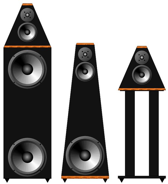
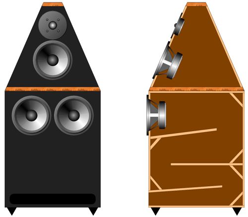
Here are the facts. Solid-state devices can unleash massive torrents of current flow. Power-supply reservoir capacitors are less expensive and more volumetrically efficient at lower voltage ratings. Output transformers perform best with lower winding ratios. In other words, we could build a solid-state 400W (80Vpk) power amplifier that ran off +/-20Vdc power-supply rails, with a step-up output transformer with a winding ratio of 1:2.5 not the 20:1 that a tube-based amplifier would use. In addition, we would use identical output devices, not complementary types, which never exactly complement each other. In other words, just N-MOSFETs or NPN transistors. With a +/-20Vdc bipolar power supply, OpAmps could drive the output stage, as they would only need to swing a few volts at their output; in addition, the OpAmps could run off regulated power-supply rails. Output transformers are intrinsically safe and offer improved impedance matching. The key point here is that this plan only makes sense with a 200Hz cutoff frequency, as bandwidth down to 20Hz at 400W requires a massive output transformer. With just a 30Hz cutoff, the output transformer should be four times heavier than the power transformer, assuming equal power ratings. Here is the idea behind the powered woofer up to 200Hz: a loudspeaker would come with its own internal subwoofer power amplifier and active crossover for the woofer. The rest of the speaker would be powered by our fancy amplifiers, with the assumption at the bandwidth only extends down to 200Hz. I can imagine such a loudspeaker being sold in two parts, as shown on the left in the image below. Or, as shown in the middle, the speaker could be made as one-enclosure unit, with the internal class-D amplifier driving the woofer.
The two-part version would allow the listener to ease his way into the high-end experience, as he might only have the resources to buy the top unit this year, and then next year the bottom unit. (Or, he might only buy the bottom half after he moves out of his small apartment into his large house.) The bottom speaker enclosure would hold the subwoofer and internal class-D power amplifier; the top speaker could be used fullrange with a fullrange power amplifier or used just above 200Hz. If used as a stand-alone speaker, as shown on the right, the highs should allow a truncating switch that would balance the high-frequency extension with the limited bass extension; but with the subwoofer in place, we flip the switch to allow full high-frequency bandwidth.
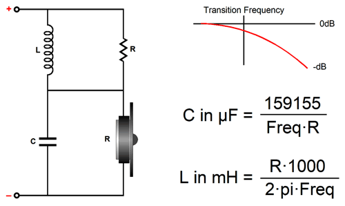
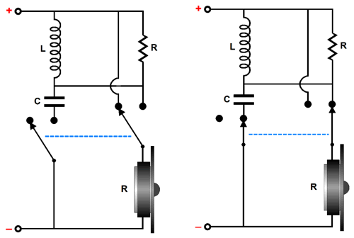
The needed switching is easy enough.
On the left, we see the tweeter running full out at high frequencies; on the right, with truncated bandwidth. In both switch positions, the load presented to the crossover is the same as the tweeter's. The highs rolloff is a soft 1st-order, -6dB per octave slope, say at 12kHz. The subwoofer speaker box need not hold a 15-inch woofer, as it could hold just two 6-inch drivers, the same driver that the top box uses as its woofer. Why? Class-D amplifiers are happier with low-ohm loads, so the two 8-ohm, 6-inch drivers would be wired in parallel. As all three 6-inch woofers share the exact same properties, the melding of the three would prove easy, as they all share the same frequency response and phase characteristics. (One driver could fire forward, while the other fired backwards from the rear of the enclosure, which would undo the enclosure's low-frequency-diffraction loss.)
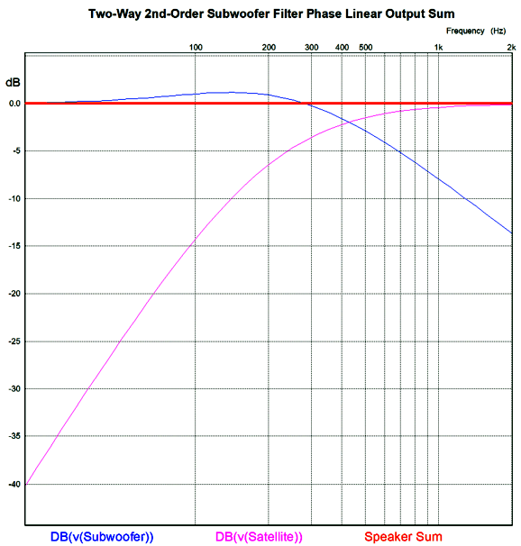
Due to the woofers being closer to the floor, their output is augmented, which could prove to be a pain in a passive speaker, as padding a woofer requires care, as high-power resistors are needed and the woofer electrical characteristics could be altered. But this is not an issue with active crossovers and internal bass power amplifier, as we just pad the input signal going to the woofer's amplifier. We could even bi-amp two 12-inch woofers, with two class-D amplifiers. The geometric-mean frequency between 20Hz and 200Hz is 63Hz, which is where we place the crossover frequency between the two woofers. Do not think of the range from 20Hz to 200Hz as just holding 180 frequencies, rather think in terms of octaves and decades, for the decade of 20Hz to 200Hz is just a significant as the one between 200Hz to 2kHz or the one between 2kHz to 20kHz. Speaking of thinking, we could think of the bottom speaker as being an active speaker stand. An industry standard might be that the frequencies above 200Hz are to be crossed over with a 2nd-order Linkwitz-Riley active filter (i.e. Q = 0.5), while the frequencies below 200Hz, get an asymmetrical, phase-flat crossover that falls away at -6dB per octave. At 200Hz, the upper speaker will be down -6dB.
Speaking of phase-flat, years ago I received an email from a reader who claimed that loudspeakers need only be flat in frequency response—not phase response —to sound good. Really? Long ago in amplifier design, it turned out that if we made a power amplifier's output flat in frequency response, we also made its phase response flat, a freebie of sorts. With loudspeakers, however, such is not the case, as a speaker can exhibit a perfectly flat frequency response, but flip and garble the phase several times across its bandwidth. Is that a problem? It only is if you have ever heard a fullrange electrostatic loudspeaker or high-quality speaker that uses only 1st-order crossovers, such as those made by Vandersteen, as the imaging can prove so breathtaking that other speakers sound twisted in comparison. Which of the following two images looks better to you?
The image on the left is chromatically accurate (i.e. its frequency response is flat), but its phase is mangled; the one on the right is phase-flat, but its frequency response is skewed. Ideally, as so often is the case, we want it all.
We all have our preferences; mine is for phase-flat, which might explain why I so enjoy headphone listening; even if the single driver's phase departs from flat, it will do so smoothly. I have know audiophiles who cannot hear stereo imaging at all, perhaps due to impairment in one or both ears, but who emphatically demand chromatic accuracy.
More Passive Crossovers
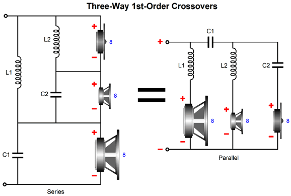
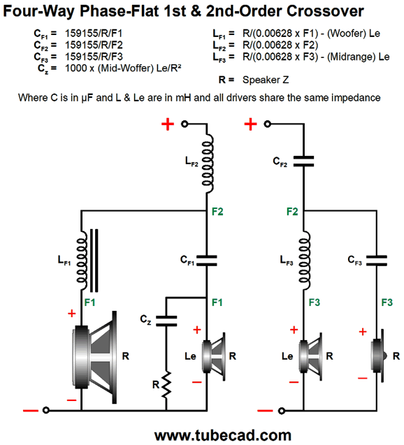
The series arrangement is more forgiving in crossover part tolerances, but requires that the same driver impedance be used throughout and it does not allow for bi-wiring. Of course, we can often mix and match parallel with series. For example, here is a hybrid parallel/series crossover for a four-way loudspeaker.
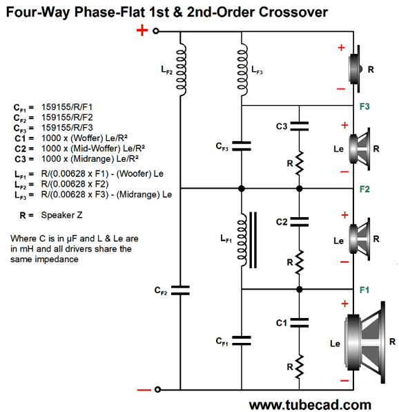
A four-way speaker requires three crossover frequencies, for example, 250Hz, 1kHz, and 4kHz. This crossover is configured as a series crossover at the center crossover frequency, then the woofer and mid-woofer see parallel crossovers, as do the midrange and tweeter. The woofer's own internal inductance is used as part of the crossover, as is the midrange's. In contrast, the mid-woofer must see a Zobel network across its leads to undo its inductance. We can also go full parallel, which allows a bi-wire setup.
In contrast, a fully series four-way crossover requires that the woofer, mid-woofer, and midrange all get their own Zobel network; thus, there is no savings in inductor millihenries to be had.
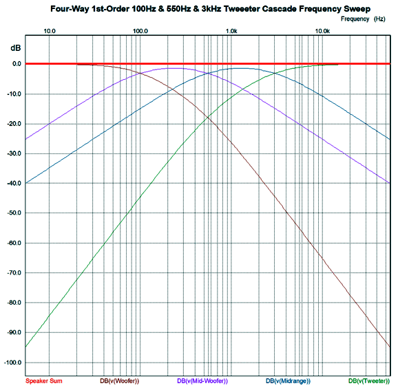
Like the previous crossover, this crossover is a 1st-order, phase-flat design, which provides progressively steeper crossover slopes for the woofer and tweeter.
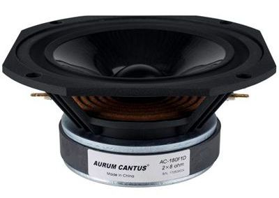
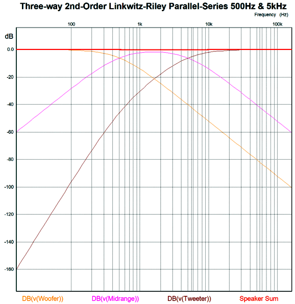
This graph applies equally to all the crossover designs. Which is better? Hard to say. Perhaps, neither outperforms the other. But I do like, however, the simplicity and inductor savings of the parallel/series version. Actually, what has been on my mind lately is the idea of using a dual-voice-coil (DVC) driver for the mid-woofer and midrange. In other words, a four-way loudspeaker that uses just three drivers. I discovered that Aurum Cantus makes an interesting dual-voice-coil mid-woofer, the AC-180F1D Mid/woofer.
With crossover frequencies of 250Hz, 1kHz, and 4kHz, the 7-inch driver would cover the heart of the music bandwidth, leaving the thumping bass for a larger woofer and the tinkling highs to a delicate tweeter. Last year, a reader asked for the math behind a three-way Linkwitz-Riley crossover. I sent him the needed formulas and a schematic, which I also meant to post here, but I forgot about them. I then remembered them, but could not find them, as I often put too much in a technical drawing file, so the file's title offers no clue to the complete contents; for example the file might be named, Class-A Autobias, but also hold crossover drawings. Well, after giving up trying to find the file, I redrew them and showed them in post 478.
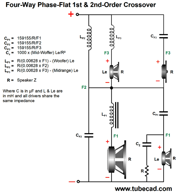
While looking through old files last week, however, I found the file. Finding the drawing I made was a delight, as it was already drawn and it looked so elegant.
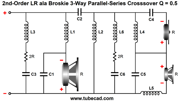
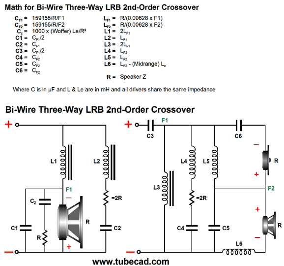
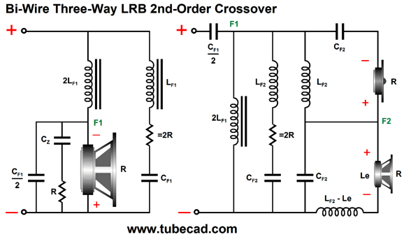
In addition, it is also a hybrid crossover that mixes parallel with series, but with 2nd-order slopes. Although this is all one needs to design the crossover, what's missing is the relations between the crossover part values, which always interest me. (I always long to see the inner logic, not just the surface appearance.) Here we see those relationships.
This crossover is not phase-flat, but it does offer far more protection for the tweeter and allows for bi-wire attachment to your amplifier.
The tweeter's initial crossover slope is 20dB per decade, but shifts to 40dB per decade as the tweeter sees the second high-pass filter between woofer and midrange. In other words, this crossover offers a tweeter cascade.
Music Recommendation: Esbörn Svensson Trio's Leucocyte I have no idea why the album is named after our blood's white cells. At the end of my first listen, I felt the urge to damn the
//JRB
*That's One Small Step for a Man—One Giant Leap for Mankind
User Guides for GlassWare Software
For those of you who still have old computers running Windows XP (32-bit) or any other Windows 32-bit OS, I have setup the download availability of my old old standards: Tube CAD, SE Amp CAD, and Audio Gadgets. The downloads are at the GlassWare-Yahoo store and the price is only $9.95 for each program. http://glass-ware.stores.yahoo.net/adsoffromgla.html So many have asked that I had to do it. WARNING: THESE THREE PROGRAMS WILL NOT RUN UNDER VISTA 64-Bit or WINDOWS 7, 8, and 10—or any other 64-bit OS. I do plan on remaking all of these programs into 64-bit versions, but it will be a huge ordeal, as programming requires vast chunks of noise-free time, something very rare with children running about. Ideally, I would love to come out with versions that run on iPads and Android-OS tablets.
//JRB
|
|
I know that some readers wish to avoid Patreon, so here is a PayPal button instead. Thanks. John Broskie
John Gives
Special Thanks to the Special 90
I am truly stunned and appreciative of their support. In addition I want to thank the following patrons:
All of your support makes a big difference. I would love to arrive at the point where creating my posts was my top priority of the day, not something that I have to steal time from other obligations to do. The more support I get, the higher up these posts move up in deserving attention. If you have been reading my posts, you know that my lifetime goal is reaching post number one thousand. I have 478 more to go. My second goal was to gather 1,000 patrons. Well, that no longer seems possible to me, so I will shoot for a mighty 100 instead. Thus, I have 10 patrons to go. Help me get there.
Only $12.95 TCJ My-Stock DB
Version 2 Improvements *User definable Download for www.glass-ware.com |
||


| www.tubecad.com Copyright © 1999-2020 GlassWare All Rights Reserved |