| John Broskie's Guide to Tube Circuit Analysis & Design |
18 January 2021 Post Number 526
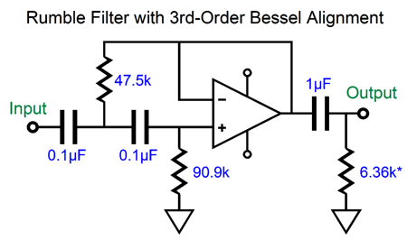
LP Rumble Filter My brother had suffered from a similar mismatch, as his stiff cartridge didn't mate well with his delicate tonearm. We wrapped several inches of solder around the cartridge end of the tonearm and all was well. My friend was stuck, as you cannot subtract mass as easily as you can add mass. What to do? My proffered solution was a rumble filter with a 3rd-order cutoff slope at 25Hz. I had memorized the math involved and soon we had all the part values needed.
He was up for it and we headed out to Radio Shack to buy a small metal enclosure, four RCA jacks, and a small perf-board. Then, we drove out to an electronics surplus store (which Silicon Valley used to be filled with), to buy some capacitors and resistors. I owned dual OpAmps that were deemed audio-grade back then (perhaps TL072s). I also owned a low-voltage bipolar power supply in its own small Radio Shack metal enclosure. About an hour of soldering later, we had a working rumble filter. How did it work? Extremely well, as his woofers no longer fought to break free of their surrounds.
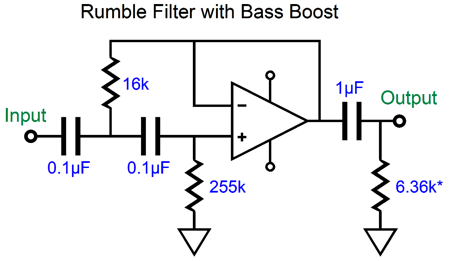
The tonearm still boogied and pranced across the LP, but the distress it caused was only visual—and only to me; remember, both the cartridge and tonearm had gotten great reviews in the audio press. So everything was also great, right? At first, yes; later, no. Few months later, he told me that the bass now seemed bit eviscerated, sounding tad thin and paltry. My solution was to switch the high-pass filter's alignment from Bessel to a peaking 3rd-order filter. All that was required was to change two resistor values. I gave him a 2dB hump at 30Hz, which then fell away at 60dB per decade. The filter's corner frequency was still 25Hz.
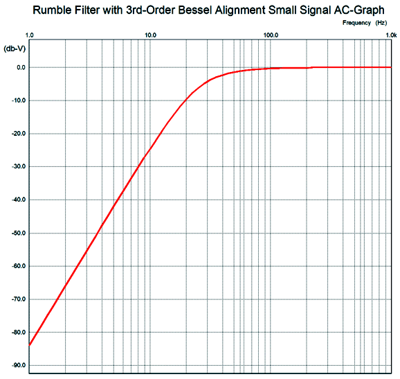
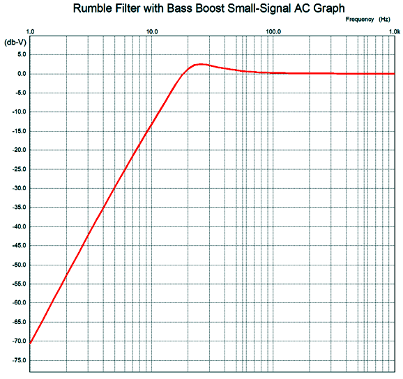
The bass bump did make a fairly dramatic improvement, considering that the 10-inch woofers would have been hard pressed to deliver much more bass. In fact, I regretted not making it peak at 45Hz and with a 6dB bump. Now that would have produced some toe-tapping bass thumps. However, since he listened primarily to classical music, I felt that some moderation was needed. How can +2dB make that big a difference? The Bessel 3rd-order filter was down about 6dB at 25Hz, so the difference was closer to +8dB, not just 2dB. About ten years later, the AD712 arrived and we swapped out the older dual OpAmp. He was delighted by the improvement, but its days were numbered, as he was moving to primarily CD listening. Here is the graph of the bumpy version.
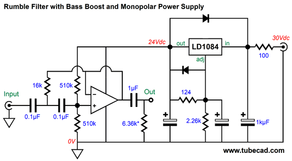
By the way with many loudspeakers, this bass bump cannot be heard, as most small 6-inch woofers fall off at 60Hz or higher. But these small speakers would still benefit from not having 15Hz warp-induced signals sent their way. Indeed, bass reflex enclosures and horn-loaded woofers would particularly benefit, as the woofers are no longer loaded adequately at these subsonic frequencies. Don't believe me? Just cover the bass-reflex loudspeaker's port with a paperback book and push the woofer in and note the resistance; then remove the book and push again and note little or no resistance. The same holds true for a horn-loaded woofer, as below the horn's low-frequency cutoff frequency, the woofer is unloaded by the horn; it will be still constrained, however, by the compression chamber behind the woofer. If I had to make the rumble filter today, I would use vastly superior OpAmps, such as the OPA627, OPA2127, and AD797 (I have heard good things about the OPA1692 in spite of it being so cheap, but it is a surface-mount device). I might forgo the bipolar power supply and opt for a regulated monopolar power supply. In other words, a switcher wallwart powering an audio-grade voltage regulator.
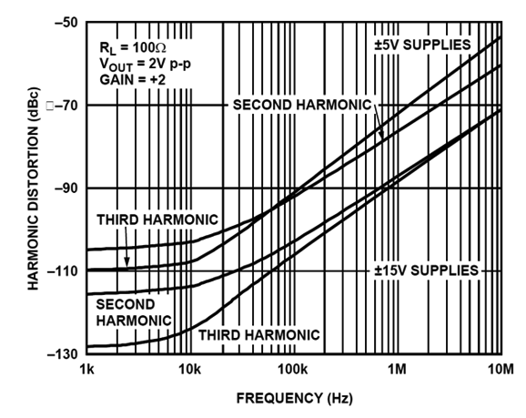
Note how the two 510k resistors are effectively in parallel; in addition, these two resistors define a two-resistor voltage divider that works to split the monopolar power-supply voltage, which allows the OpAmp's output to swing symmetrically positively and negatively. I would use high-quality, tight-tolerance capacitors throughout, not so much to establish an exact cutoff frequency, but to ensure that both channels track each other in terms of phase. A nice extra feature would be an in-out switch, so we could bypass using the rumble filter when it was not needed. The 24Vdc regulator B+ voltage may seem excessive, but it does offer some advantages. For example, the peaking is greater at the OpAmp's output than it is after the coupling capacitor at the output, so extra headroom is helpful. In addition, OpAmp distortion is often lower with higher power-supply rail voltages. Here is a graph from the AD811 datasheet.
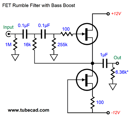
Note the substantial improvement and the further reduction of the third harmonic. Of course, nothing stops us from building a discrete rumble filter using FETs or transistors or tubes—or any combination of all three technologies. A unity-gain buffer can easily be built from FETs, as only two FETs are required per channel.
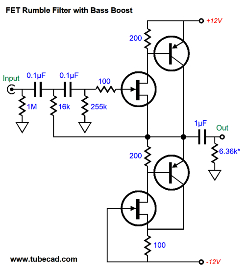
The bottom FET functions as a constant-current source, while the top FET works as a source follower. We can further hotrod this circuit by adding PNP transistors.
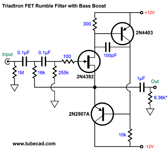
The top FET enslaves the top transistor, while the bottom FET yokes the bottom transistor's current conduction. We can even drop the bottom FET by using a triadtron topology.
The FET draws a nearly constant current, while the two transistors vary their current conduction. FETs are getting rare these days. The problem we face with transistors is that they draw base current, which against the high resistor values creates big voltage shifts. One workaround is to use a half-diamond input circuit.
Another workaround is to use skewed resistor values, which in parallel still equal the desired 255k.
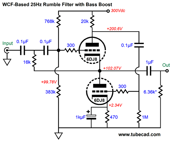
Okay, John, that's all great, but what about tubes? We can use tubes, no problem; all we need is a single cathode follower per channel. Of course, we could get fancier. Here is a White cathode follower inspired peaking rumble filter.
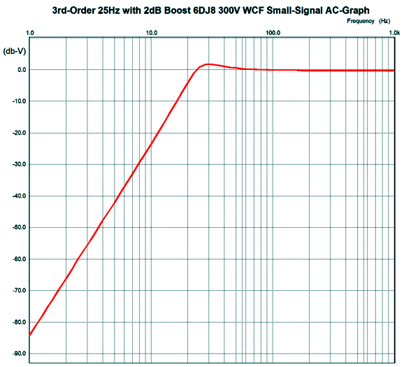
This White cathode follower is optimized for low output impedance, not equal push-pull operation; thus, the huge plate resistor value of 20k. In SPICE simulations, the output impedance came in at about 4 ohms. In fact, the top triode effectively functions as constant-current source, while the bottom triode drives the external load resistance. Here is the frequency plot.
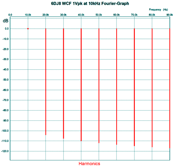
Looks just like the OpAmp version. In addition, the distortion is equally low. Here is the SPICE-generated Fourier graph for 1Vpk at 10kHz.
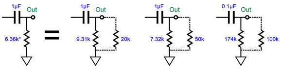
Not bad at all. I tried replacing the plate resistor with a constant-current source, but no real improvement in THD resulted. However, PSRR did improve a bit. The problem is that the PSRR is great at 1kHz, but not at the crossover frequency of 25Hz. In other words, a well-regulated power supply is required. I have yet to explain the asterisks after the 6.366k resistors. We need to factor in the line-stage amplifier's volume potentiometer's value. Typical values are 20k, 50k, and 100k.
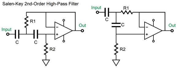
Before leaving this topic, I should say something about the Salen-Key active filter. Let's start with the 2nd-order high-pass filter.
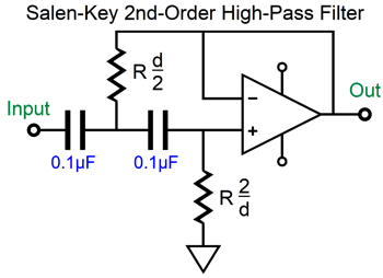
I have drawn the circuit in the two usual formats used, but the topology is identical in both. Resistors R1 and R2 set the high-pass cutoff frequency with the two 0.1µF capacitors. The larger the resistor values, the lower the cutoff frequency. The filter's damping is the inverse of its Q. So, a Q of 0.5 equals a damping of 2. The Linkwitz-Riley 2nd-order crossover Q is 0.5. The famous Butterworth filter alignment presents a Q of 0.707, so a damping of 1.414. To find the need resistor values, we use the following formula to find the 1st-order high-pass resistor value. R = 159155/C/Frequency Where C is in µFs. For example, 25Hz requires a 63,662-ohm resistor with a 0.1µF capacitor. The next step is to follow the following ratio.
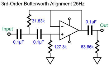
For example, if we desire a 25Hz high-pass Butterworth filter, R1 must be 63,662 times 1.414/2 or 45k; R2 must be, 63,662 times 2/1.414 or 90k. Note that the product of R1 against R2 must equal 63,662² or 405284736. This holds true for any damping or Q for a 25Hz high-pass filter. In other words, no matter what the ratio between R1 and R2 is, the product of the two multiplied against each other must equal the 1st-order resistor value squared. Since the Linkwitz-Riley 2nd-order crossover Q is 0.5, its damping is 2; and since 2/2 is 1, resistor R1 and R2 vales are the same and equal to the 1st-order resistor value. When we desire a 3rd-order filter, we can cascade a 2nd-order filter with a Q of 1 with a 1st-order filter with a Q of 0.707, which combine to create Butterworth 3rd-order filter with a Q of 0.707.
For a Bessel (Thomas) alignment, the math is different, which you can see from comparing this filter schematic to the first one shown at the top. No Linkwitz-Riley 3rd-order crossover exists, nor does it need to, as the Butterworth 3rd-order crossover sums to flat, like the 2nd-order Linkwitz-Riley.
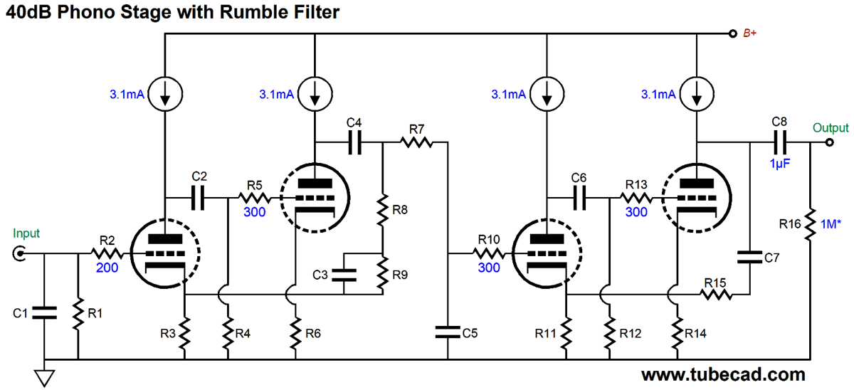
40dB Phono Stage with Built-In Rumble Filter
Since the phono stage amplifies millivolt signals up to 1Vpk, the constant-current sources need not drop much voltage, as no large output swings are required. The RIAA equalization uses both active and passive networks, active for the bass boost from 500Hz down to 50Hz and passive for the 2122Hz (75µs) low-pass filter. A subtlety here is that the input triode's cathode DC voltage passes along with the audio signal to the second two-triode feedback pair, which saves us one coupling capacitor. Nonetheless, there are four coupling capacitors from input to output, which raises the danger of low-frequency peaking because of the negative feedback—if we do not choose the part values carefully. In other words, this is not a circuit that allows us to use just any part we find in our parts bin. Capacitors C2, C4, C6, and C7 and resistors R4 and R12 must not be altered in value. The same holds true for the critical RIAA equalization parts, C3, C5, R8, and R9.
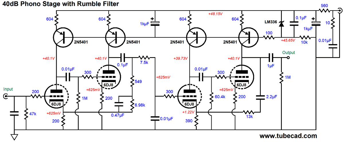
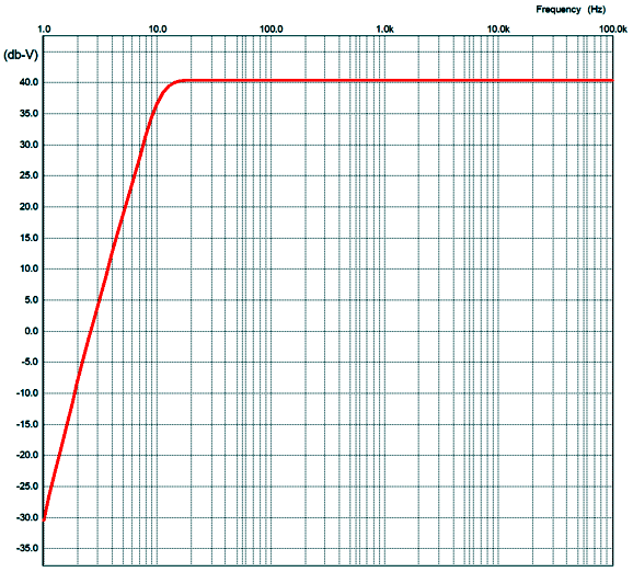
We see just how low a B+ voltage I had in mind, 56Vdc raw input power-supply voltage that goes through an RC filter (the 560-ohm resistor and 1kµF capacitor) to scrub away the high-frequency hash from a 56V switcher desktop power supply. The four PNP transistors are configured as constant-current sources. Here is the SPICE-generated frequency plot.
Note the sharp low-frequency cutoff and the otherwise flat frequency response. With DACs, we worry about the high frequencies; with phono stages, the low frequencies. Motor noise, warped records, off-center holes—all produce low frequency noise. Sometimes the loudspeaker bass reproduction creates a positive feedback with the turntable and cartridge, causing huge low-frequency problems. In fact, with some tweaking of part values, we could raise the cutoff frequency from 13Hz to 30Hz. By the way, the other idea behind this phono stage is that the 56Vdc switcher would also heat the heater elements. A four-6DJ8 Aikido line-stage amplifier would be included, so the eight heaters in series would need 48Vdc, which a separate RC filter would provide, along with zener shunts, so when the phono stage wasn't needed, the zeners would take up the current flow, which would still provide 24V for the line-stage amplifier heaters.
Music Recommendation: Totem I found an interesting interview with Romano at debbieburkeauthor.com that reveals his goals and missions. That Romano is so young impresses me all the more and fills me with anticipation of what he will produce in the coming decades. This album has made many best-albums-of-2020 lists with good cause. //JRB
User Guides for GlassWare Software
For those of you who still have old computers running Windows XP (32-bit) or any other Windows 32-bit OS, I have setup the download availability of my old old standards: Tube CAD, SE Amp CAD, and Audio Gadgets. The downloads are at the GlassWare-Yahoo store and the price is only $9.95 for each program. http://glass-ware.stores.yahoo.net/adsoffromgla.html So many have asked that I had to do it. WARNING: THESE THREE PROGRAMS WILL NOT RUN UNDER VISTA 64-Bit or WINDOWS 7, 8, and 10 if the OS is not 32-bit or if it is a 64-bit OS. I do plan on remaking all of these programs into 64-bit versions, but it will be a huge ordeal, as programming requires vast chunks of noise-free time, something very rare with children running about. Ideally, I would love to come out with versions that run on iPads and Android-OS tablets.
|
I know that some readers wish to avoid Patreon, so here is a PayPal button instead. Thanks. John Broskie
John Gives
Special Thanks to the Special 88 To all my patrons, all 90 of them, thank you all again. I want to especially thank
I am truly stunned and appreciative of their support. In addition I want to thank the following patrons:
All of your support makes a big difference. I would love to arrive at the point where creating my posts was my top priority of the day, not something that I have to steal time from other obligations to do. The more support I get, the higher up these posts move up in deserving attention.
If you have been reading my posts, you know that my lifetime goal is reaching post number one thousand. I have 474 more to go. My second goal was to gather 1,000 patrons. Well, that no longer seems possible to me, so I will shoot for a mighty 100 instead. Thus, I have 12 patrons to go. Help me get there.
Support the Tube CAD Journal & get an extremely powerful push-pull tube-amplifier simulator for TCJ Push-Pull Calculator
TCJ PPC Version 2 Improvements Rebuilt simulation engine *User definable
Download or CD ROM For more information, please visit our Web site : To purchase, please visit our Yahoo Store: |
|||


| www.tubecad.com Copyright © 1999-2021 GlassWare All Rights Reserved |