| John Broskie's Guide to Tube Circuit Analysis & Design |
29 July 2021 Post Number 541
Speaker Diffraction Loss
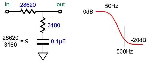
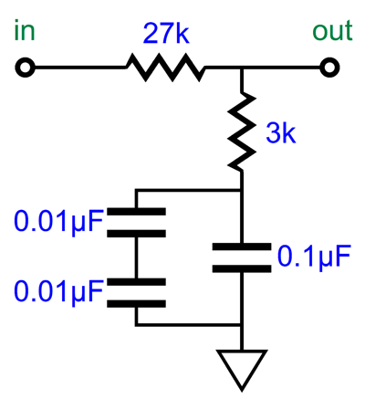
This got me thinking that we might be able to exploit the clean ratio of 9 to 1, as some of the standard 1% resistor values (the E96 set) abide by the ratio; for example, 1.8k and 16.2k, 2k and 18k, 3k and 27k, 2.7k and 24.3k. (There might be more, but I cannot readily think of them.) Of course, the bigger problem is that so few 1% capacitor values exist. In other words, we might have gotten a perfect 9:1 ratio in resistor resistances, but we now have to find a corresponding 1% capacitor value, which is not likely to be made. For example, if we use 27k and 3k resistors, we need a 0.105µF capacitor to impose the 3180µs and 318µs time constants and the 50Hz to 500Hz shelving function. Well, we could easily buy a 1% 0.1µF capacitor and then place two 1% 0.01µF capacitors in series and to make 0.005µF worth of capacitance, which we would then place in parallel with the 0.1µF to make exactly 0.105µF.
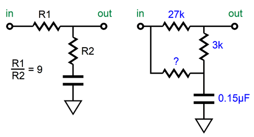
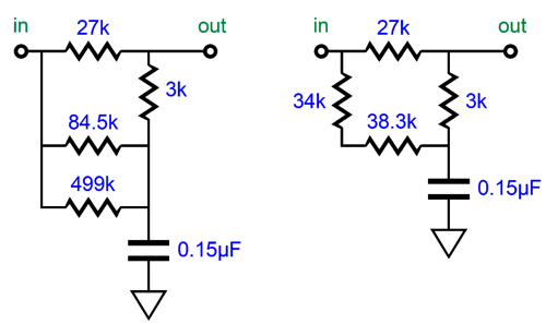
Another workaround would be to buy the nearest larger 1% capacitor value and shunt the two resistors with a third resistor. For example, Vishay makes a 1% 0.15µF polypropylene capacitor, which divided into 3180µs equals a total resistance of 21200 ohms.
The 3k and 27k resistors add up to 30k, but 30k in parallel with 72,273 ohms equals 21.2k. Sadly they do not make a 1% 72273-ohm resistor (they do, however, make an E192 0.1% 72.3k resistor). But if we use 84.5k and 499k resistors and place them in parallel, we get 72263 ohms; or if we place 34k and 38.3k resistors in series, we get 72.3k ohms.
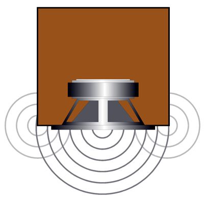
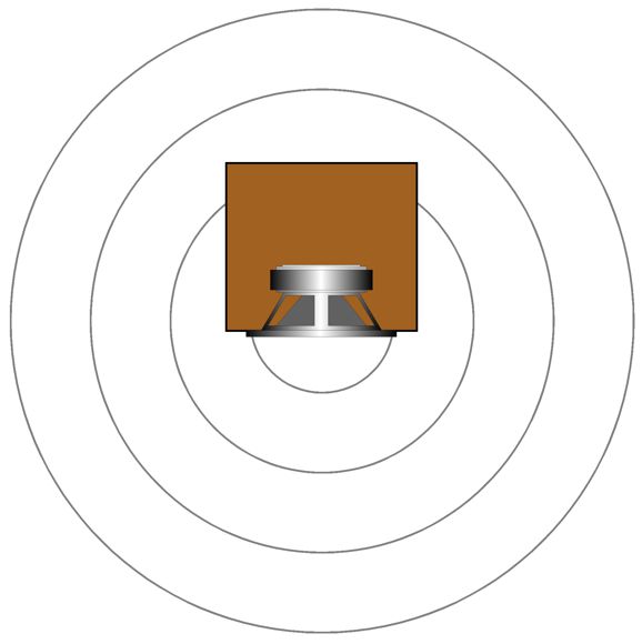
As you can see, there are many ways to trim an RIAA equalization network. The important takeaway here is that the desired 50Hz to 500Hz shelving function obtains with the shunting resistors in place. Well, as so often happens, this solution to the problem of fixed even ratios sent my mind down an entirely different path, i.e. loudspeakers. Small speaker sitting atop a stand away from the walls suffer from the problem of diffraction loss (aka speaker-baffle step response). Diffraction loss results in thinning bass response, as the loudspeaker goes from radiating primarily forward at high-frequencies (2pi), but omni-directionally (4pi) at low frequencies; in other words, half a sphere to a complete sphere. When the speaker cabinet width is greater than the wavelength of the frequency produced, the sound radiates forward; but when the width is substantially narrower than the wavelength, the speaker radiates the low frequency in all directions, which causes a -6dB drop in SPL. The lower the frequency, the larger the wavelength. At 1kHz, the wavelength is about 13.5 inches; at 100Hz, 135 inches; and at 10Hz, 1350 inches.
The web offers many solutions and formulas to work around this problem. The drawback, however, is that they often do not work. For example, we seldom suffer the full textbook -6dB drop in bass, but something less, say -4.5dB. In addition, the solution of placing a passive bass-boost network within the loudspeaker enclosure extracts an insertion loss equal to the amount of boost. In other words, if the speaker nominally puts out 90 dB with 1W of power, it will put out 84 dB with 1W with the bass-boost network. Moreover, the series resistor within the network will both get hot and will upset ( at least) the woofer's crossover filter. For these reasons, I have built small loudspeakers that used a passive shelving network between the line-stage amplifier and the power amplifier.
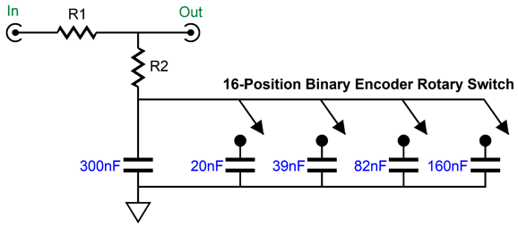
No resistors get hot with this arrangement and the amplifier's output impedance remains unchanged, but the amplifier effectively quarters in power at low-frequencies, as it must deliver twice the peak voltage. The real problem was getting the amount of bass boost and the transition frequency right, which required a huge amount of experimentation, which was not easy four decades ago. Today, we can easily use our smart phones to take SPL readings and frequency response tests. If we are willing to spend $300, we can buy a calibrated microphone and acoustic measurement system software. In other words, we can fairly accurately measure the results. This is a huge advance, but we still face the issue of building and modifying the shelving network for the optimal bass reproduction. Theory, however, has a hard time matching reality, as loudspeaker enclosures are seldom round or even square and few houses hold anechoic rooms. A speaker cabinet's rectangular front makes for complicated formulas and the room itself introduces bass boosts of its own, as the floor and back wall and nearby corner limit 360-degree radiation. Indeed, just using a taller speaker stand can undo the previously successful shelving network. Ideally, we need a piece of test equipment that would offer a wide range of transition frequencies and a varying amount of bass boost. For example, I would like to see a selectable frequency range of 300Hz to 600Hz and attenuation from -2dB to -6dB, in 0.5dB steps. Stereo is not needed in this test gear, as we need only test one loudspeaker. The last time I thought of this project, I was convinced that my binary capacitance arrangement for phono cartridge loading offered the best solution for selecting different transition frequencies. A 16-position binary encoder switch and for capacitors (20nF, 39nF, 82nF, and 160nF) would allow for making sixteen 20nF steps in capacitance (we would need a starting shunting capacitor as well, say 300nF). See post 483 for more details.
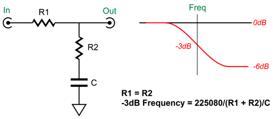
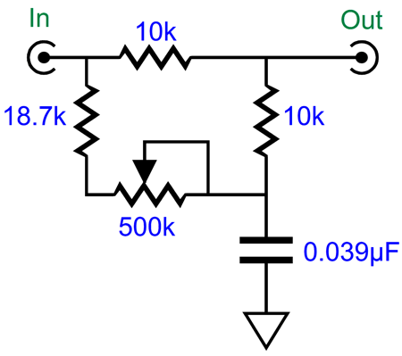
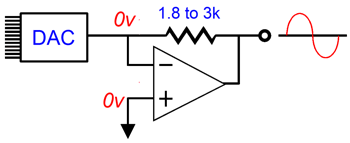
But having seen how we can shunt the two-resistor pair in the RIAA equalization shelving network, allows me to see how we could get away with not changing any capacitor values. First, let’s start by ignoring any variations in attenuation; in other words, let's assume that the textbook diffraction loss always creates a -6dB bass shelving attenuation. This makes things easy, as -6dB of attenuation results from a two-resistor voltage divider that yields 50% of the input signal at its output. Thus, all we need is two equal valued resistors soldered in series and terminated by a capacitor to ground. Next, we must find a way to shunt the two-resistor voltage divider with a varying resistance, so we can move the transition frequency up and down.
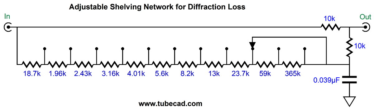
At one extreme, the two-resistor voltage divider is shunted by only 18.7k; at the other extreme, 518.7k. As we change the shunting resistance, we change the transition frequency. With 518.7k of shunting resistance, the transition frequency is 300Hz, with an 18.7k shunting resistance, 600Hz. Alternatively, we could use an 11-position stepped attenuator.
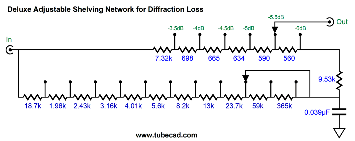
If the shelving network's transition frequency is too low, the loudspeaker frequency response will flatten but with a peak. On the other hand, If the shelving network's transition frequency is too high, the loudspeaker frequency response will still flatten but with a dip. When we hit the target transition frequency, the speaker's low-frequency response will be flat. Well, that's the theory. As I mentioned before, just where the loudspeakers are located in the room will alter bass reproduction. One great thing about the venerable Klipschorn was that the designer knew where it was going to be placed. A bookshelf loudspeaker resting on an actual bookshelf will deliver an entirely different bass response that it would sitting atop 2-foot stands four feet away from the back wall. Here is a deluxe version that includes a stepped attenuator that selects both the transition frequency and the amount of bass boost.
The added six-position rotary allows us to make 0.5dB adjustments in the bass boost.
Current-Input 2nd-order Filter
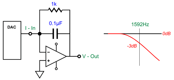
Whatever the cause, reader, Gaspard, raised an interesting question: Can the I-to-V conversion circuit that turns the DAC's current output into signal voltage hold a low-pass filter? What Gaspard had in mind was the following.
Indeed, this will impose a low-pass filter, but the capacitor value is far too high, as the -3dB down frequency is only 1592Hz. Most DACs recommend a low-pass filter frequency closer to 100kHz (some SACD playback DACs hold a 50kHz low-pass filter). For example, the AK4414 DAC's datasheet recommends a 125kHz, Q=0.692, 2nd-order low-pass filter. The circuit shown above is a 1st-order type. The interesting question is can we make a 2nd-order version that accepts input current, not input voltage? We can, but first we must look into the multiple-feedback filter (MFB). The punch line is that the MFB filter is a better active filter, which explains why it is often used in demanding audio applications, such as high-dynamic-range ADC input stages. It is slightly more complicated than the equivalent non-inverting Salen-Key filter, so it is largely unknown to most audiophiles.
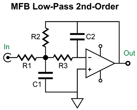
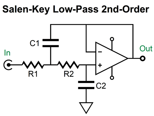
The multiple-feedback filter is based on the inverting amplifier topology, whereas the Salen-Key is based on the non-inverting topology. This makes a big difference, as the assumption behind the Salen-Key topology is that the buffer's output actually realizes absolute unity-gain; no buffers do.
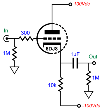
In contrast, the multiple-feedback filter relies on there being phase inversion of the input signal, which there always is. In addition, the MFB's initial RC filter (R1 and C1) are outside the OpAmp's feedback loop, so this pre-filter is essentially passive, therefore incapable of overload (other than the capacitor arcing or the resistor bursting into flames, neither are likely with typical audio signals). In short, the multiple-feedback filter does not run out of steam the way the Salen-Key filter does. Here is a simple example, using a cathode follower as the unity-gain buffer.
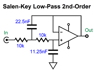
The 6DJ8-based cathode follower delivers a gain of about 1:0.91; in other words, we present 1V of input signal to the grid and we get 0.96V of output signal at the cathode. (This assumes an external load impedance of 100k.) The output impedance is about 90 ohms. Not a bad buffer, in other words. But when we try to make a Salen-Key 2nd-order low-pass filter based on this cathode follower, the results fall far short of our expectations.
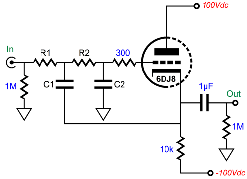
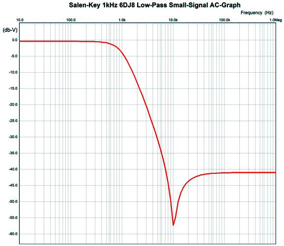
The 10k resistors (R1 and R2) and capacitors simply present too great a load to the cathode follower. Here is the SPICE-generated AC graph for this 1kHz, Butterworth 2nd-order filter.
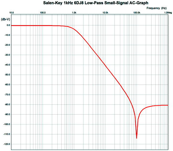
Note that the falloff starts well, but then stalls, then climbs, and the flattens to -41dB. If we replace the 10k resistors with 1M resistors and decrease the capacitor values by 100-fold, we can squeeze an extra decade of low-pass filtering.
The problem with high-ohmage resistors is increased resistor noise and, potentially, DC offsets with transistor-based circuits. Switching to an FET-input OpAmp improves performance, but it, too, runs out of steam.
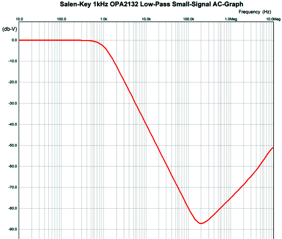
Here is the plotline for the OPA2132-based 1kHz filter with 10k resistors.
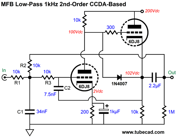
At around 196kHz, the filter falters, then climbs up at 12dB per octave. By placing a simple 1st-order RC filter after the filter, we can at least flatten the output beyond 196kHz; for example, a 1k resistor and 1nF capacitor. Okay, let's now look at the multiple-feedback filter with a simple 6DJ8-based CCDA (constant-current-draw amplifier). The CCDA inverts the input signal at its output, which allows us to use it in the MFB configuration.
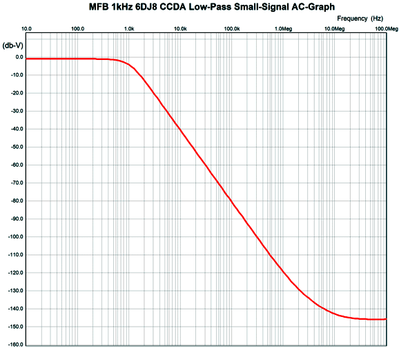
The filtering action eventually flattens, but not at the cathode follower's limit of 10kHz, but at 10MHz. Since the output is -140dB down, however, we can pretty much ignore this departure from expectations.
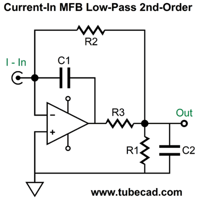
Okay, now that we have had a taste of the MFB filter, let's look at how we can reconfigure the resistors and capacitors to create a current-input version.
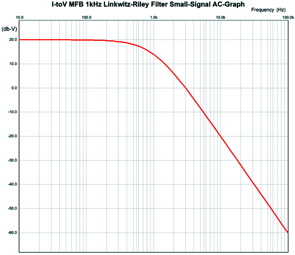
This topology creates an I-to-V conversion circuit with a 1kHz 2nd-order Butterworth low-pass filter overlay. What is the conversion ratio? One milliamp creates 10V of output, as resistor R2's value sets the ratio. By the way, we are not limited to the Butterworth filter alignment, as we can impose either a Bessel or Linkwitz-Riley alignment. For example, here is a 1kHz Linkwitz-Riley low-pass filter with a gain of 10, as 1mA of input current will produce 10V of output signal in volts.
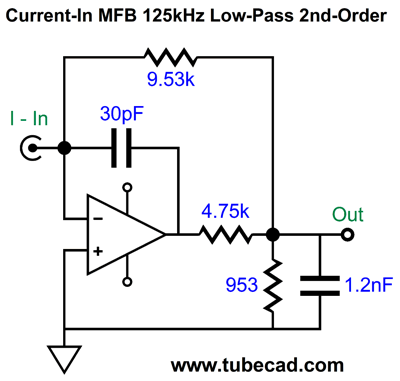
Note the 20dB baseline, which implies a gain of 10. Thus, at 10kHz, this filter is down -40dB, not -20dB. (If we desire a lower current-to-voltage conversion ratio, say 1mA to 1V, we divide all resistors and capacitors by ten.) How do we work out the needed resistor and capacitor values? For example, recalling the parameters required for the AK4414, a 125kHz, Q=0.692, 2nd-order low-pass filter, here are the values needed.
We can resort to textbook formulas:
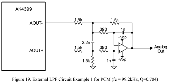
The web now fills with calculators. (Sadly, some are earnest but bogus, as the underlining math is wrong, sometimes laughably so.) In contrast, the OKAWA Electric Design website's calculators seem quite accurate, as behooves a Japanese electrical-engineering website. The downside to their calculators is that they allow the entry of many more variables, which will confuse many newbies. For example, nowhere can you select between Bessel and Butterworth and Linkwitz-Riley filter alignments. The workaround is to specify a Q of 0.577 for Bessel; 0.707, Butterworth; and 0.501, Linkwitz-Riley. Returning to Gaspard's situation, his DAC puts out unbalanced current; in contrast, most DACs now put out balanced voltage signals. If you look in the accompanying datasheets, you see MFB low-pass filters like the following.
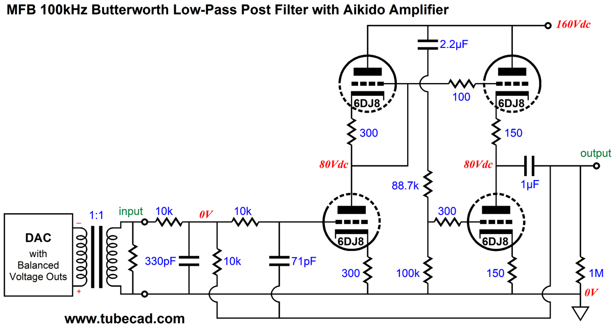
Can we translate this circuit into tubes? We could, but it would take some effort. On the other hand, we could build the following:
The OpAmp version took care of DC offset output voltages from the DAC, as teh DC offset is treated as common-mode signal; in this version, the input signal transformer does the same, as primary sees no net DC current flow, even if each output sits at 1.5Vdc. In addition, the transformer delivers CMRR and creates an unbalanced output signal. The Aikido-based MFB low-pass filter kicks in at 100kHz and delivers a gain equal to twice the output voltage from the DAC (one phase only).
Music Recommendation: Crime Of The Century I was 14 as I entered the 1970s, and I left at age 24. Those were truly formative years. At the time, I felt let down by the music of that decade, as it seemed to have failed to deliver on the promise of 1960s music. Where the 60s produced The Beatles, the 70s delivered disco. Jazz was dead. Blues likewise. Transistors and ICs did a number on classical-music LPs, tainting the recordings with screechy and brittle highs; the once great RCA label now produced Dyna-Groove LPs unworthy of the shaded dog logo. Thus, I sought substance and relief in music from the 40s, 50s, and 60s. Of course, compared today, the 1970s was a golden age of music. Fleetwood Mac released Roumors; the Sex Pistols exploded on the scene; Blondie bewitched; Bruce Springsteen announced that he was born to run; Michael Jackson was still black and still normal; Pink Floyd broke down the wall that separated them from most listeners; The Rolling Stones released Brown Sugar and Led Zeppelin, Stairway To Heaven; Dolly Parton smashed it with Jolene; and Al Green and Marvin Gaye sang with soul. The young man handing me my sandwich asked if I had any recommendations from that long ago period. I did. I mentioned the song All the Young Dudes, by Mott the Hopple. Not only did he know the song, but God overheard our conversation and the song played on the radio station. In unison, we both said, "No way." The next time I bought a sandwich, I recommended Paul Kossoff's album, Back Street Crawler, especially the song, Time Away. Apparently, God was otherwise busy, as the song did not play from above us. Okay, what does this egregiously long preamble have to do with Supertramp's 1974 album, Crime of the Century? It would be a damned shame if younger readers didn't know this album. It is a an audiophile's dream album with stunning clarity and sassy saxophone-graced arrangements. Their third and breakthrough album, Crime of the Century, is a concept album, much like Pink Floyd's The Wall; and it, too, aches and drips with 1970s existential depression. Life sucks, especially life in England sucks. School and society suck, as does just about everything else in Rudy's life, Rudy being the protagonist of the album. Since I am a cheerful pessimist, I can groove on this sort of progressive-rock angst, much in the same way that Kafka would break out laughing while reading aloud his dark fiction to friends. (I once recommended to a friend Sergei Rachmaninoff's bleak symphonic poem, Isle of the Dead, as I found it wonderfully depressing, completely devoid of hope, ending where it started in dark depths, bereft of expectation and promise. My friend reprimanded me by pointing out that I was a happy person who liked depressing music, but that he was a depressed person who liked happy music.) Amazon Music Service offers a 192kHz, 24-bit version of the Crime of the Century. Tidal offers a "Master" version, which I assume means MQA.
//JRB
Did you get your money's worth with this post by me? If so, think about supporting me at Patreon.
User Guides for GlassWare Software
For those of you who still have old computers running Windows XP (32-bit) or any other Windows 32-bit OS, I have setup the download availability of my old old standards: Tube CAD, SE Amp CAD, and Audio Gadgets. The downloads are at the GlassWare-Yahoo store and the price is only $9.95 for each program. http://glass-ware.stores.yahoo.net/adsoffromgla.html So many have asked that I had to do it. WARNING: THESE THREE PROGRAMS WILL NOT RUN UNDER VISTA 64-Bit or WINDOWS 7, 8, and 10 if the OS is not 32-bit or if it is a 64-bit OS. I do plan on remaking all of these programs into 64-bit versions, but it will be a huge ordeal, as programming requires vast chunks of noise-free time, something very rare with children running about. Ideally, I would love to come out with versions that run on iPads and Android-OS tablets.
|
I know that some readers wish to avoid Patreon, so here is a PayPal button instead. Thanks. John Broskie
John Gives
Special Thanks to the Special 81 To all my patrons, all 84 of them, thank you all again. I want to especially thank
I am truly stunned and appreciative of their support. In addition I want to thank the following patrons:
All of your support makes a big difference. I would love to arrive at the point where creating my posts was my top priority of the day, not something that I have to steal time from other obligations to do. The more support I get, the higher up these posts move up in deserving attention.
If you have been reading my posts, you know that my lifetime goal is reaching post number one thousand. I have 439 more to go. My second goal was to gather 1,000 patrons. Well, that no longer seems possible to me, so I will shoot for a mighty 100 instead. Thus, I have 19 patrons to go. Help me get there.
Support the Tube CAD Journal & get an extremely powerful push-pull tube-amplifier simulator for TCJ Push-Pull Calculator
TCJ PPC Version 2 Improvements Rebuilt simulation engine *User definable
Download or CD ROM For more information, please visit our Web site : To purchase, please visit our Yahoo Store: |
|||


| www.tubecad.com Copyright © 1999-2021 GlassWare All Rights Reserved |