| John Broskie's Guide to Tube Circuit Analysis & Design |
16 April 2005 
Amplifier auto bias circuits: Class-A, Class-AB! Ideally, in a class-AB push-pull amplifier, the goal is to set just the right amount of overlap between output devices to attain the transfer function that is closest to linear. In addition, the problem of aging and failing tubes arises. The bias voltage that works so handsomely when the output tubes were new may not work as well a few months later or when one output tube is replaced. With solid-state devices, the problem of heat-dependent current variations in the output stage must be addressed. Transistors are particularly egregious offenders when it comes to heat-induced current changes. The transistor exhibits a large positive temperature coefficient: as the device gets hotter, it conducts more; the more it conducts, the hotter it gets...until it burns out. There are workarounds, such as emitter resistors and thermal auto-bias adjustment circuits, but each brings its own set of problems. MOSFETs, on the other hand, (usually) display a negative temperature coefficient: as the device gets hotter, it conducts less. Because of the MOSFET’s degenerative response, as opposed to the transistor’s regenerative response, the MOSFET survives where a transistor would burn out. (Not all MOSFETs are operated past their negative temperature coefficient transition point, which means that they too need a thermal auto-bias adjustment circuit to compensate for the heat induced bias misadjustments.) Vacuum tubes live and breathe in heat and do not surfer from the solid-state problems of a heat-shifted bias point. However, tubes do age. Over time, the bias voltage required to establish a desired idle current will vary. In a fixed-bias amplifier, adjustments can be made as needed, which might be as often as daily or as infrequently as yearly, depending on the tubes. In a cathode-biased amplifier, the cathode resistor offers a stabilizing degeneration in idle current variations. If the tube conducts too much, the cathode voltage increases, which decreases the idle current. Unfortunately, this technique is not perfect. 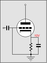
If nothing else, the large-valued cathode resistor steals potential watts from the output and adds extra heat to the amplifier’s chassis. In addition, the cathode resistor must be bypassed with a large-valued capacitor, which brings its own imperfections to the mix. Finally, cathode-biased amplifiers work best when run in class-A, as class-AB amplifiers suffer from a tube-induced-rectification distortion. When a class-AB cathode-biased amplifier sees a prolonged burst of signal, the output tubes' conduction can easily increase fivefold over the nominal idle current setting. This increase in cathode current will slowly charge up the bypass capacitor, which will effectively increase the negative bias voltage, as the grid will become more negative relative to the cathode. This new bias voltage will slowly collapse over time, but until then the amplifier will distort greatly as the output tubes might even be completely cut off after the large signal burst (surely, "no output signal" must come as close as you can get to "100% distortion"). 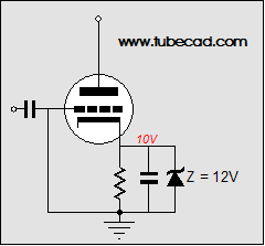
One workaround that I have used (and never seen used elsewhere) is to place a zener in parallel with the cathode resistor. The zener’s break voltage is purposely set higher than the bias voltage, so that when the amplifier leaves class-A, the zener limits the maximum voltage the capacitor can charge up to, which prevents under biasing the amplifier after a large current swing. The past: Auto-bias circuits (I know that many tightly wound audiophiles claim that DC servo circuits pollute the sound of otherwise blameless amplifiers, but after 25 years of designing and using DC servo circuits, I have never encountered a sonic liability. Maybe I have been lucky; or maybe I have just been extra careful; or maybe some people have designed such poor-performing servos that they do intrude into the audio signal. In fact, I would love to see such a circuit and explore its failings.) Class-A amplifiers are the best candidates for an auto bias circuit, as the average of the current flow equals the idle current. For example, an output tube biased in class-A might experience a dynamic current swing of +200mA down to 0A, with an average value of 100mA, the same value as its idle current. In this case, the simple DC servo circuit below works handily. 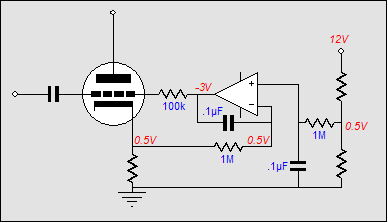
The small-valued cathode resistor allows us to read the current flowing through the output tube by measuring the varying voltage that develops across it via the connection to the 1M resistor. The 1M resistor terminates into the OpAmp’s inverting input and the 0.1µF capacitor. Any deviation from the reference voltage at the OpAmp’s non-inverting input will be met with a correction voltage at the OpAmp’s output. If the tube conducts too much, the OpAmp’s output will swing negatively; if too little, positively. Once again, but in greater detail: effectively, the 1M resistor is grounded (in AC terms) at its connection to OpAmp, as the OpAmp will do all it can to keep both its input pins at exactly the same voltage, and since the non-inverting input is set at DC reference voltage, the inverting input will steadily mimic the AC-free input. When the cathode resistor swings up in voltage, the 1M resistor will pull current up out of its connection with the capacitor, which must see its connection to the OpAmp’s output swing negatively to counter this current. Thus, the capacitor becomes charged negatively relative to its connection to the 1M resistor. But when the cathode resistor swings down in voltage, the 1M resistor will source current into of its connection with the capacitor, which must see its connection to the OpAmp’s output swing positively to counter this inrush current, which will charge the capacitor positively relative to its connection to the 1M resistor. If the signal is symmetrical and its frequency is higher than the resistor and capacitor’s transition frequency, then the capacitor will display no net change in voltage across its leads, as the two-direction swings average to zero. Below the resistor-capacitor transition frequency, the capacitor will not be able to suppress any voltage movement at the OpAmp’s inverting input and the OpAmp will see the signal at its inverting pin and it will invert and amplify it, causing the OpAmp’s output to alter its DC output voltage. This circuit works beautifully as long as its reference voltage is steady, as long as the amplifier does not amplify asymmetrical signals, and as long as the output stage’s current swings are within in the class-A envelope of operation. A reference voltage should be noise-free and temperature-independent. Fortunately, cheap, excellent IC voltage references are readily available. Protracted asymmetrical signals are rare in most music, although some instruments do produce asymmetrical waveforms, such as the trumpet and piano. Usually, the input signal averages to something close zero with most non-electronic music (with computer-generated music, who knows). The last requirement is the hardest to meet. Reactive loads and wide dynamic ranges conspire to kick the output stage out of class-A into class-AB operation. Once the output stage leaves class-A mode, the DC servo will see a net DC increase at its inverting input and it will strive to bring the amplifier back into line with its reference voltage. Given a long enough period of excessive current swinging, the bias voltage will be thrown far too negative and the once class-A amplifier might end up operating in class-C, as the output devices might be completely biased off (of course, some tubes are so sloppy at their cutoff region that they never cut off). If a global feedback loop is in place, the feedback will try to save the day, but distortion will still be quite high; in the absence of feedback, the amplifier may not amplify input signals below its new DC bias threshold, producing grotesque distortion as a result. 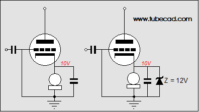
A cathode-bias alternative is easy to implement. The cathode resistor is replaced with a capacitor-bypassed constant-current source. The constant-current source strives to maintain a constant DC current draw and the bypass capacitor shunts the AC sign to ground. The constant-current source can be made from another tube or from solid-state devices, the latter being much cheaper and more reliable. For example, a lowly LM317 makes an excellent constant-current source in this application, as it only requires one resistor and a bypass capacitor. Unfortunately, the same problems of asymmetrical signals and output stage’s current swings outside the class-A envelope of operation limit this circuit’s usefulness. The same workaround that was suggested for the cathode-biased amplifier can be used here: a zener in parallel with the cathode resistor, which limits the bypass capacitor voltage charging after a large current swing. More to come //JRB |
The Tube CAD Journal's first companion program, TCJ Filter Design lets you design a filter or crossover (passive, solid-state or tube) without having to check out thick textbooks from the library and without having to breakout the scientific calculator. This program's goal is to provide a quick and easy display not only of the frequency response, but also of the resistor and capacitor values for a passive and active filters and crossovers. TCJ Filter Design is easy to use, but not lightweight, holding over 60 different filter topologies and up to four filter alignments: While the program’s main concern is active filters, solid-state and tube, it also does passive filters. In fact, it can be used to calculate passive crossovers for use with speakers by entering 8 ohms as the terminating resistance. Tube crossovers are a major part of this program; both buffered and un-buffered tube based filters along with mono-polar and bipolar power supply topologies are covered. . Downloadable version (4 Megabytes file). Download or CD ROM
|
|||


| www.tubecad.com Copyright © 1999-2005 GlassWare All Rights Reserved |