| John Broskie's Guide to Tube Circuit Analysis & Design |
| |
||||
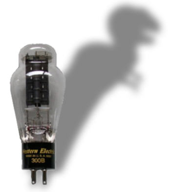
18 January 2005 T-Rex Dick Olsher has created a mighty 300B amplifier: the T-Rex (Toroidal King, in other words, as the amplifier uses Plitron toroidal output transformers, power transformers, and chokes). Steve Bench and I have lent a helping hand and the DIY article is available at Enjoy the Music.com. The T-Rex is big, complex, and expensive. It certainly isn’t your father’s 300B amplifier. And few will have the resources to build the T-Rex, but then the T-Rex is not a Volks-amplifier. I see it as being much like a concept car at an auto show, something that inspires, rather than something to buy in a corner auto lot. I highly recommend that you give the article a read, as it is explanation filled, explaining how shunt regulators and partial feedback are used in the amplifier’s design. (Enjoy the Music took a big gamble in publishing this article, as the site is not a DIY site and this is not a trivial 300B amplifier, so be sure to check the article out to let them know that high-standard DIY tube projects are worth the effort.) Shunt Regulators 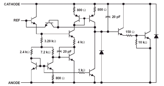
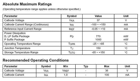
The only problem is—albeit a small problem, but a problem nonetheless—the schematic above is the TL431's simplified internal schematic. As great as the TL431 might be, many ask too much of it, either demanding it withstand too much voltage or draw too much current. The TL431 can only withstand 36 volts, so the circuit below is definitely a bad idea. 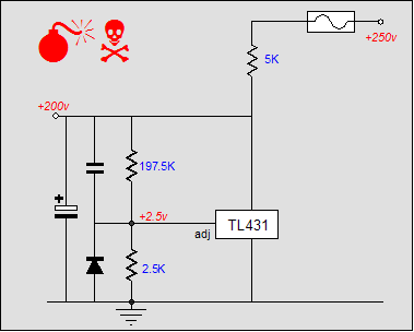
The TL431 can only source up to 100mA, so the circuit below is equally a bad idea. 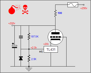
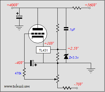
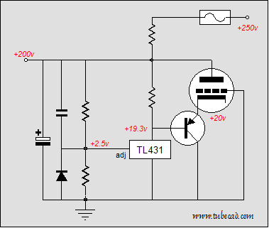
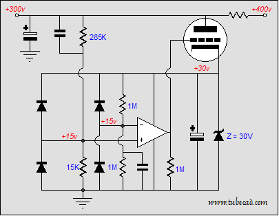
The above table was lifted from the Fairchild TL431A PDF and it lists the limits within which the device will operate. Note, the TL431 cannot see 36 volts across its leads and draw 100mA at the same time, as that would result in 3.6 watts of dissipation, far more than the 770mW that it can withstand. (Also note that 770mW limit is at a cool 30° Celsius and must be derated for higher temperatures.) Extending the TL431’s voltage limit is easy enough, as we can cascode the TL431 with either a tube or a transistor or a MOSFET (placing a zener in series with it is neither safe nor desirable). Above we saw a tube sitting atop the TL431; below, a high-voltage MOSFET sitting atop. 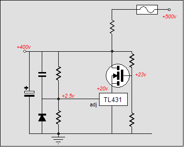 The potential problem with the tube-based hybrid shunt regulator is that at turn-on the tube’s cathode is cold and not conducting, which means no voltage regulator until it is hot. Second, the triode might require a much larger negative bias voltage than the TL431’s 36 volt limit. The workaround is to use a negative power supply connection to help bias the triode.
Here the triode sees a –50 volts grid-to-cathode bias voltage, while the TL431 only sees a 10 volt differential. (The optimal anode-to-cathode voltage for the TL431 would equal (36V – 2.5V) / 2 + 2.5V, as it would allow the greatest cathode swing on the TL431.) 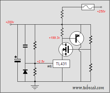
Or
If the load draws a fairly steady current, as single ended circuits and class-A output stages tend to do, then the shunt regulator need only make up the delta in current draw between minimum and maximum, plus whatever wall voltage fluctuations that must be compensated. In other words, 40mA is way too much current, as a total (shunt regulator and load) current draw of 60mA would probably be more than sufficient. SRPP shunt regulators 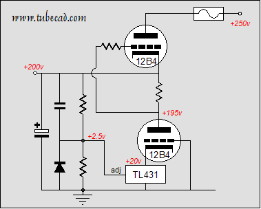
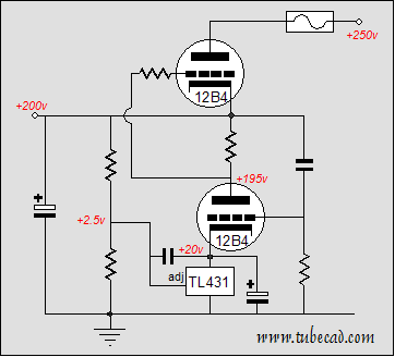
For some, the thought of letting a IC control the output of the shunt regulator is as scary as letting a IC control the sound coming out of a tube amplifier. The circuit below uses the TL431 to adjust the DC output voltage of the regulator, while the 12B4s control the AC output of the regulator.
TL431-less shunt regulator
//JRB |
|
|||
| www.tubecad.com Copyright © 1999-2005 GlassWare All Rights Reserved |
