| John Broskie's Guide to Tube Circuit Analysis & Design |
| Big Amplifiers 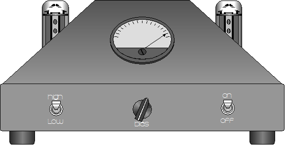
|
||||
19 March 2005 Big amplifiers
While at the CES in January, I was surprised to find so many gargantuan tube amplifiers: huge, massive, expensive amplifiers, many the size of small refrigerators or big air conditioners. These amplifiers held more glass than my wallet could bear to contemplate. The motives are obvious: these days power and overindulgence are both desired and marketable. I have to admit that I was ambivalent: on one hand, I was impressed by the audacity of the amplifiers and I do appreciate what such a powerful amplifier can bring to a large-orchestra composition, such as any of Mahler’s later symphonies. On the other hand, I was disappointed to see the more-must-be-better philosophy win. (Have you ever noticed how easily many over compensate: the bald man who buys a toupee the size of a dead opossum, the A-cup woman who moves up to double D. Imagine if he had bought the smallest, thinnest toupee made, which only partially covered his scalp, no one would guess that he was wearing a rug. Or, imagine if she had stopped at a B cup, no one would know that she had visited a surgeon.) Beyond philosophical objections to big for the sake of big, big amplifiers face a few design hurdles. For example, high-wattage MOSFETs and transistors are much poorer performers than comparable low-wattage devices. And with tube amplifiers, big output transformers seldom sound as good as small transformers to my ears. (I own pairs of the big Tango 120 watters and Heathkit WM-6s.) Why? I am not exactly sure. My guess is that the small output transformer holds a higher ratio of copper to iron. Or, maybe that the small transformer is easier to make well because of its smaller coil bobbin. But if I had to place a bet, it would be on the output transformer bringing its own distortion in the form of magnetic hysteresis in the core, which is most notable in the smallest signals; and with big output transformers, the small signal becomes too large, requiring large output swings to overwhelm. Of course, if your loudspeakers are highly inefficient, then you have taken a giant step sideways by moving up to a big amplifier. Single-ended amplifiers do not suffer from this problem, as the output transformer’s core is always magnetized in one direction that never reverses, so this hysteresis effect is never encountered. This probably explains why horn loudspeakers work so well with single ended amplifiers, as they work with just a few tenths of a volt of signal (additionally, most horn-loaded speakers exhibit a good deal of 2nd harmonic distortion due to the compression chamber not exactly matching the horns input impedance, which if phased correctly, can be largely undone by the single-ended amplifier’s counter-balancing distortion). Still, there are times when a big amplifier is the only amplifier that will work in a system and I do believe in lots of headroom.
Design example: four Dynaco ST-70s The easiest answer is to cascade enough cable splitters to feed four ST-70 sub amplifiers through one channel’s signal and then strap all four outputs together. Will this work? Yes and no. if your speakers are 2 ohm, yes; if 8 ohm, no. The Dynaco ST-70’s output transformer, the P-431, holds a primary impedance of 4300 ohms, when the 8-ohm tap is loaded with an 8-ohm load. And since the four output transformers are in parallel, the winding ratio remains constant, so the same 4300 ohms is reflected with the 8-ohm load. 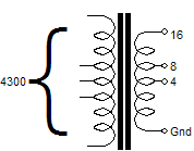
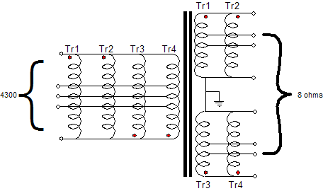
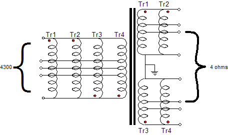
A 4300-ohm load, however, is not what eight EL34s need to see to put out 140 watts. Remember that four times the watts into the same load means twice the output voltage, but the output tubes must follow the same plate-voltage swings as before. In other words, because we have quadrupled the number of output tubes, we must quarter the plate-to-plate impedance. In other words, in order for eight EL34s to put out 140 watts, they need to see a plate-to-plate load of 4300/4, or 1075 ohms. One solution is to use a 2-ohm load across the 8-ohm tap and ground, as this impedance against the output transformer’s impedance ratio (the winding ratio squared) equals 1075 ohms. Another solution is to attach 4-ohm loudspeakers across the 16-ohm tap and ground, as this impedance will reflect down to 1075 ohms. What if you don’t own 4-ohm loudspeakers? The only answer is to reconfigure the secondaries, so that an 8-ohm load reflects down output 1075 ohms. If two transformer’s secondaries are placed parallel and then placed in series with another pair placed in parallel, as shown below, the 8-ohm loudspeaker will reflect the desired 1075 ohms and the speaker will see twice the output voltage than one ST-70 would deliver.
Note how the ground connection has been moved to the center. This move has its advantages and disadvantages. On the plus side, we can attach the output tubes’ cathodes to the outside ends of our center-tapped secondary, which allows for a simple feedback loop to be realized. On the minus side, more loudspeaker connecters are needed, as we have to reattach both speaker leads, when we change the speaker’s impedance. (Most loudspeakers are either 4 or 8 ohm in impedance, so only four connectors are actually needed in most situations.) Also note how transformers Tr3 and Tr4 have their primaries flipped relative to transformers Tr1 and Tr2. This is necarsary to compensate for their secondaries being flipped relative to the other secondaries.
Design example: two Dynaco ST-70s
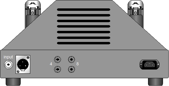
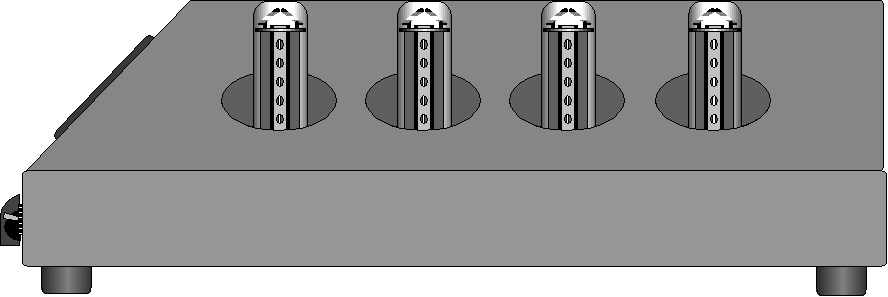
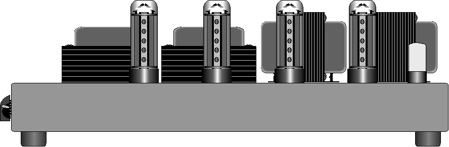
More pictures
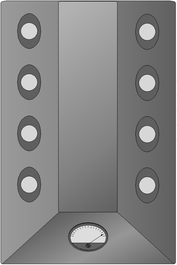
Click on above image to see enlargement
Click on above image to see enlargement
//JRB |
Only $12.95
Download or CD ROM www.glass-ware.com |
|||


| www.tubecad.com Copyright © 1999-2005 GlassWare All Rights Reserved |