| John Broskie's Guide to Tube Circuit Analysis & Design |
21 May 2005 
More auto bias circuits
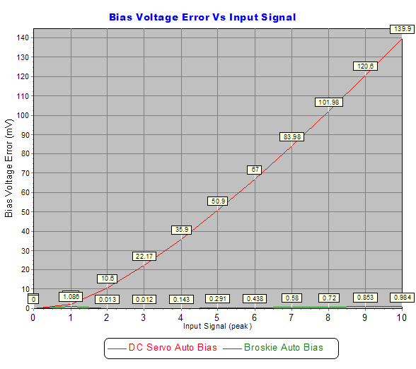
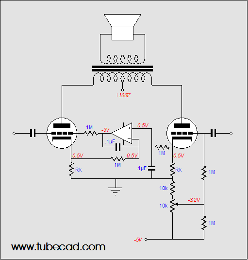
One reader wanted to see how the Broskie auto-bias circuit could be used with power output tubes; above is a more fleshed-out version of the Broskie auto-bias circuit that would work well with a set of power tubes like the 6L6, EL34, KT88 or 2A3—or even a single output tube. One reader asked if the clipping or Broskie auto-bias circuits were suitable for single-ended amplifiers. The answer is yes, as SE amplifiers often (almost always is closer to the mark) exhibit a rectification effect, unless a great deal of feedback is applied. The graph below compares the generic DC servo auto-bias circuit against the Broskie auto-bias circuit. The tube is a single 6DJ8 and it falls out of class-A operation after 1V of input signal, so we should only look at the first few input volts of the graph to compare the two circuits use in a single-ended amplifier.
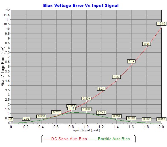
Below is a closeup of the first two volts of input signal.
As the graph clearly shows, both circuits work exactly the same up to about 0.6 volts of input signal; thereafter, the Broskie circuit performs much better with the remaining class-A range and beyond. Blumlein auto bias
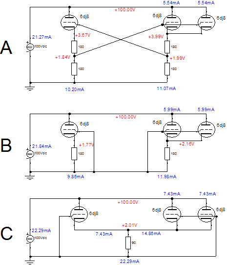
Shown below, Blumlein came up with an auto-bias matching circuit that does not aim to set a specific idle current, but works to keep both output tubes conducting the same idle current; a current balancer, in other words. He realized that a mismatch in idle current would steal performance from a push-pull amplifier, as it would lead to partial magnetizing of the output transformer’s core, which reduces its inductance, worsening its low-frequency reproduction, and which limits its maximum output wattage, as the transformer prematurely saturates in one direction. His circuit, know as the “garter circuit,” cross feeds a sampling of each output tube’s current conduction via a tap in the cathode resistance to the other tube’s grid. As one tube conducts too much, it raises the bias voltage on its fellow tube’s grid. Conversely, if a tube conducts too little, it lowers the bias voltage on its fellow tube’s grid, causing the tube to reduce its conduction. 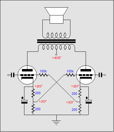 Blumlein "garter" circuit How well does it work? Better than you might expect, but with a few caveats. A shootout between the Blumlein garter circuit and two alternatives is needed. I used SPICE and I created a greatly mismatched set of output tubes by using two tubes in parallel, effectively creating a new tube with the same mu, but twice the gm and half the rp. (No bypass capacitors were added, as no AC signal was used in the simulation.) Ideally, when both output tubes are perfectly matched, the idle current should equal 9.86mA in the Blumlein circuit. As shown in figure (A) below, one tube conducts 10.2mA, while the other conducts 11.07mA, a mismatch of 0.87mA, or 8.5%; not too bad, considering the grotesque mismatch in tubes. Using separate cathode resistors (B) yields poorer results: a mismatch of 2.12mA, or 21.5%. And using a single common cathode resistor (C) produces the worst results: a mismatch of 7.43mA, or 100%.
So, given these results, which topology do you think has found the widest acceptance? The single common cathode resistor is the winner; it is immensely popular, much more so than the dual cathode resistors, and Blumlein's circuit is all but forgotten. Why use only one shared cathode resistor? Because it cheaper to implement, with only one bypass capacitor needed, and because far too many believe that using a single common cathode resistor will transform any amplifier into a class-A amplifier, regardless of the resulting idle current. Unbelievable, but sadly true. Just ask a musician and see what he tells you. Of course in a world wherein a circlotron amplifier is seen as being a dual, single-ended, class-A-by-necessity design by many audiophiles…but I won't go on. Unfortunately, Blumlein’s circuit displaces B+ voltage that could be used to create more power output. Additionally, it requires the bypass capacitors to be rated twice as high in voltage than otherwise would be used.
A modern approach to bias balance
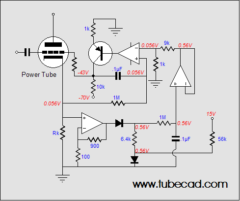
Because the time constant is the same for both the voltage reference’s RC circuit (1M and 0.1µF) and the OpAmp’s RC feedback circuit (1M and 0.1µF), this circuit handles class-AB and class-B output stages quite well. Note that in the schematic that OpAmp connects directly to the leftmost triode’s grid resistor. This arrangement only works when efficient output tubes are used, which need a grid voltage that goes down to –15 volts but no farther. Two workarounds are possible: use an asymmetric power supply for the OpAmp or add a PNP transistor to the OpAmp’s output, as in the Broskie auto-bias circuit shown at the top of this page. Usually, an OpAmp is attached to a bipolar power supply of +/- 15 to 20 volts. However, we can use a skewed power supply, with +5 and –25 volts to –35 volts, as the OpAmp will only see the same voltage differential between its power supply pins. (Actually, we might even get away with forgoing the positive power supply rail altogether, as several OpAmps can accept positive input signals that extend beyond their positive power supply voltage, for example the BiMOS CA3140: Absolute Maximum Ratings Alternatively, a current mirror can be used in place of the OpAmp. In the schematic below we see the leftmost output tube following the rightmost idle current. 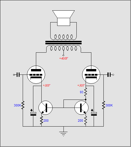
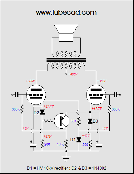
The rightmost transistor is wired as a diode (and could be replaced with a diode, such as the 1N4001), so the effective cathode resistor used by the rightmost output tube is a 293-ohm resistor with a solid-state diode in series with it. The leftmost transistor works to establish the same emitter voltage that the rightmost transistor does, which ensures that the same idle current is experienced by both output tubes.
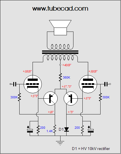
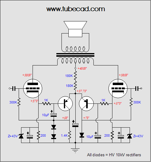
Or, we can replace the OpAmp with a simple transistor-based differential amplifier, with a long tail that extends up to the output stage’s B+ voltage. (The 360k resistor is as good as a constant-current source in this circuit because of its large value.) Diode, D1, is a high-voltage rectifier that exhibits a forward voltage drop of 7 volts (internally, seven diodes are wired in series). This diode is used here as a low-current voltage reference, which is important because we do not want the differential amplifier to draw more than 1mA total. (Zener diodes require far too much current conduction to break at such a low voltage.) This diode's forward voltage drop sets the range of possible negative voltage adjustment, as the diff-amplifier’s output cannot swing below ground in this circuit. (If a negative power supply is available, then much smaller cathode resistors can be used and the diff-amplifier’s out could swing down to the negative power supply voltage.) A more-fleshed out version is shown below. The zeners are used to limit the rectification effect of the output tubes undergo in heavy use. The added capacitors filter away the AC signal that might be present on the cathodes. All in all, not a bad circuit—particularly, when no negative power supply is available.
Since this diff-amplifier draws its power primarily through the rightmost output tube, the leftmost tube must see an equal load current, otherwise our balancing circuit will in itself unbalance the output stage; thus, the connection of the 30k resistor and high-voltage diode to the left output tube’s cathode and ground. (The 1.4k resistor should be bypassed with a capacitor, as should be diode, D1, as these added capacitors will slow the turn on for the output tubes and shunt away extra AC signals. Next time Speacial thanks
//JRB
|
Help keep the
The Tube CAD Journal's first companion program, TCJ Filter Design lets you design a filter or crossover (passive, solid-state or tube) without having to check out thick textbooks from the library and without having to breakout the scientific calculator. This program's goal is to provide a quick and easy display not only of the frequency response, but also of the resistor and capacitor values for a passive and active filters and crossovers. TCJ Filter Design is easy to use, but not lightweight, holding over 60 different filter topologies and up to four filter alignments: While the program’s main concern is active filters, solid-state and tube, it also does passive filters. In fact, it can be used to calculate passive crossovers for use with speakers by entering 8 ohms as the terminating resistance. Tube crossovers are a major part of this program; both buffered and un-buffered tube based filters along with mono-polar and bipolar power supply topologies are covered. . Downloadable version (4 Megabytes file). Download or CD ROM
|
|||


| www.tubecad.com Copyright © 1999-2005 GlassWare All Rights Reserved |