| John Broskie's Guide to Tube Circuit Analysis & Design |
22 May 2006 Spoiled
To be frank, although by the third day I was close to being back in form, what a slow climb it was (in spite of my using several tricks, such as pre-soldering components on to tube sockets before attaching the socket to the chassis). I shouldn’t complain too loudly, though, as I have friend who can no longer even bear to solder parts to PCBs, so he pays others to do it for him. So, what was I soldering together? I was so tickled by my Aikido-as-single-ended-amplifier-front-end experiments that I modified my single ended amplifiers to hold an Aikido circuit, using a 12SL7 as the input tube and a 12SN7 as the buffer tube, followed by two EL34s in parallel. How did it turn out? Much nicer than I expected, to be honest. Paradoxically, the Aikido’s four triodes sound much purer, less cluttered, than the single triode they replaced, which sounded diffused and slightly blurred by comparison. But wait—don’t different tubes and different coupling capacitors have different sounds? Could it be that it wasn’t the Aikido but rather the different input triode and coupling capacitor making all the difference? This is a good point to bear in mind; but in this case, I used the same the triode type (even the same tube) and the same coupling capacitor (in fact, the same operating point for the input tube), so the Aikido circuit must get credit for unleashing the latent clarity in the 12SL7.  How does the Aikido circuit perform this feat of sonic magic? The Aikido circuit loads its input tube with a symmetrical impedance, which is made up from the same triode and the same valued cathode resistor. This improves the linearity by loading a nonlinear device with a complementary (in other words, a balancing) nonlinear load. Second, the input stage does not have to drive any real load, as the Aikido’s buffer output stage offers a hugely-high input impedance. Additionally, the Aikido’s buffer output stage strips the power-supply noise from the first stages output signal. Thus, the Aikido’s output is about as good as it gets, which is why I was surprised by the improvement in the single ended power amplifier. Huh? A single ended power amplifier’s output, when not ironed flat by feedback, is not linear, with 5% to 10% distortion being quite common. Moreover, its PSRR is not that good and its gain is usually limited to less than 20dB. Therefore, one would imagine that the Aikido’s lack of distortion would be masked—indeed steamrolled—by the output stage, just as the Aikido’s low noise would be drowned out by the output stage’s louder noise. (Actually, I had implemented my Aikido-like treatment to the output stage, so it was actually quiet to start with.) I believe the answer lies in that most important first watt of output, where 90% of music lives. Yes, a single ended amplifier’s distortion is high at full output, but even then it is mostly 2nd and a little 3rd harmonic. On the other hand, there is no crossover distortion, no power supply bouncing up and down, no discontinuity in the tube’s transfer function—all of which make single ended sound magical. The Aikido circuit just made that first watt sound even better. So, while the full-power specification had not improved radically on the amplifier, the crucial first watt was charmingly and gracefully polished.
12SL7s and 12SN7s 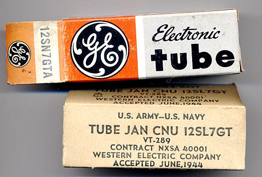 The 6082 Those who are good at math will have spotted a discrepancy: 12.6V + 12.6V = 25.2V, not 26.5V. Indeed. Although 26.5V is only a 5% over-voltage, it would be better to under-heat the heaters, so a 25.2V power supply could be used for all the tubes; or the 26.5V power supply could be used, if one of the jumpers (J4) was replaced by a 1N4001 diode ( or two diodes) or a 4.3-ohm (or larger) resistor. 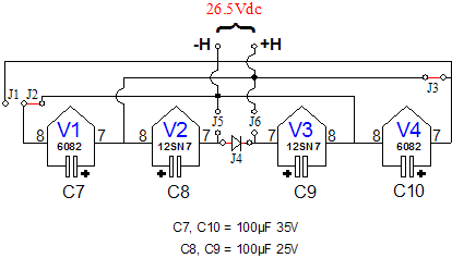
What is a 6082? This tube is functionally the same as the 6AS7/6080, except for the high heater voltage and low heater current draw (600mA, opposed to 2.5A). It can deliver a huge amount of current with very little plate voltage, which makes it a good candidate for a headphone amplifier or even a parallel-feed power amplifier, albeit a low-wattage amplifier.
Free DC voltage for heaters 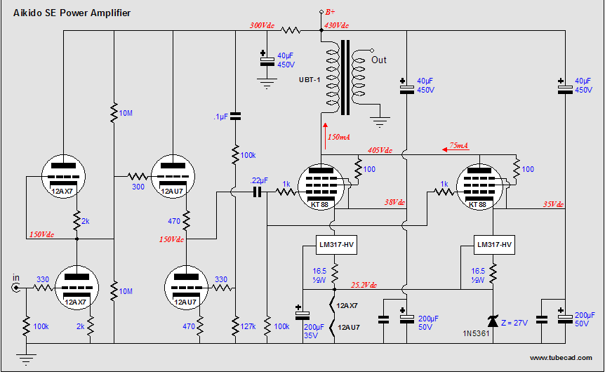
In the schematic above, each triode could hold its own constant-current source to ensure that each tube draws 75mA. This required the addition of just two three-pin voltage regulators. The constant-current sources will help prevent damaging the heater filament which, when cold, draws far more current than when hot. In addition, it will keep each tube biased correctly regardless of age or tube-tube variation. For those who sicken at the mere sight of solid-state devices, the regulators can be replaced by 157-ohm resistors. Below is the SE Amp CAD's evaluation of the output-stage circuit shown above. 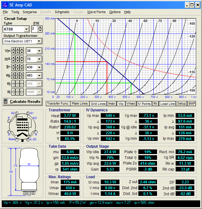 Is DC on the input stage tubes worth it? Yes. I find that the low bass improves with DC, gaining definition. Just why this is so is puzzling, as the thermal time constant for the heaters is long; so the answer must lie somewhere else. Maybe just lower hum explains it. Next time
//JRB
|
|
| www.tubecad.com Copyright © 1999-2006 GlassWare All Rights Reserved |
