13 September 2006
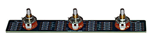
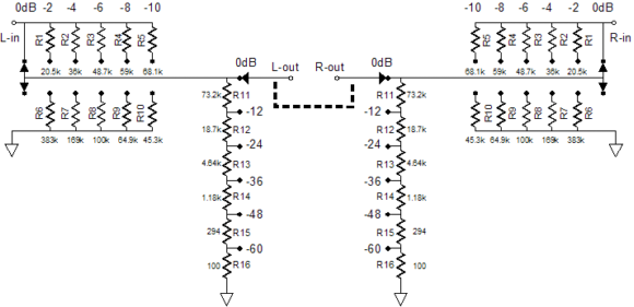
In addition to precise 36 steps of attenuation, the attenuator allows balance adjustments to be made, which I find critical to fine tuning the stereo image. By the way, most men in America have a weaker left ear; apparently, driving a car with the window down can damage ears. Where I live in California, no one would ever buy a car (or a house) without an air conditioner, so this may not hold true here. Nonetheless, few have balanced hearing by middle-age.
(I used to know this audiophile who argued that true stereo imaging required 1/100 of dB adjustments. Sure, but make certain that your hair is combed exactly the same way each day and, God forbid, if you cannot maintain a 1/10 of a millimeter head positioning.)
A further advantage this attenuator offers is that it is a small, bite-sized project that can easily be built in less than an hour. Remember those two projects you planned on building some seven years ago? The three-chassis, 845-based headphone amplifier and the fully-balanced, seven-staged, phono preamp requiring 20 tubes? Well, unlike them, this attenuator can actually be built in the time that it takes to hear a Beethoven symphony (three could be built during a Mahler symphony).
Speaking of actually building a tube hi-fi project, instead of just storing parts in your closet, my enthusiastic recommendation of Morgan Jones’s book, Building Valve Amplifiers, becomes even more persuasive. I get e-mails all the time that outline the most amazingly majestic tube projects that each writer hopes to build. For example,
“I want to design a tri-ampped, GM70-based, DSP equalized, SE, OTL, capacitor-free, integrated amplifier that uses a battery power supply with three shunt regulators, and accepts balanced and un-balanced inputs, with a 256-step attenuator and a remote control that dynamically adjusts the bias and the B+ on the output tubes and…But I have no idea how cathode biasing works or even why it is needed …”
Well, I do not know much about angels and only a bit more about fools, but I know for certain that I would sure fear to tread anywhere in this direction. Moreover, designing such an impressive project is only half the battle; the other half is actually building it.

Most Americans—and many Europeans—would hate to study Karate in Japan. The reason lies neither in anything as obvious as the burden of having to learn Japanese nor as mundane as the hassle of not being able to find a parking spot in Tokyo, but in the Japanese way of teaching Karate. In Japan, you will not receive a black belt until you have both studied and taught for years. Until then, you will wear a white belt, as the multi-color spectrum of belts is a Western invention (Paris, France, in 1935), developed to appease the impatient. Even more maddening for the overeager student would be the Japanese practice of not teaching any kicks or punches in the first year. Instead, the first six months are spent in preparing the body with exercise and stretching; the second six months, learning how to fall without injury.
All electronic projects ask for some care in their construction; tube-filled projects absolutely demand it. High voltages are dangerous—indeed, lethal. A solid-state project, powered by a 15-volt power supply, may spark and smoke if miswired, but it is unlikely to kill anyone. Tube-based projects are not always so lucky. I have read that as little as 38-42 volts is all that is required to kill someone under the worst-case scenario. Besides danger, tube-based projects bring a few wrinkles of which the solid-state hobbyist knows little or nothing. As T. S. Eliot put it: "The last thing one discovers in composing a work is what to put first." In other words, first pay your armchair dues by reading Building Valve Amplifiers, before you turn on the drill press and soldering iron.
It has been a while since I last touched on the topic of using the cathode-follower topology in an output stage.
Blog 48
Blog 49
Blog 50
Blog 52
Blog 53
Blog 54
I had covered mono-polar power supplies and positive-and-negative bipolar power supplies, which left out the bipolar power supply that holds two positive voltages. I had saved the best for last, but I never got to the end.
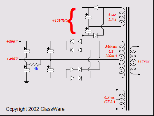
The above PS circuit uses solid-state rectifiers and yields two B+ voltages.
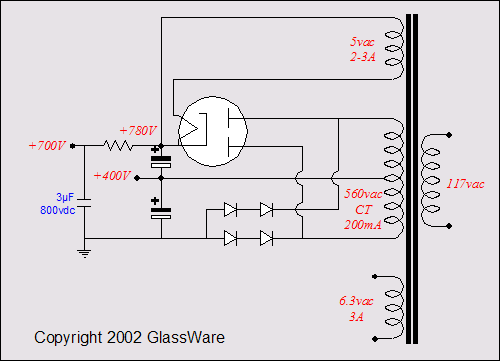
This variation uses both a tube and solid-state rectifiers.
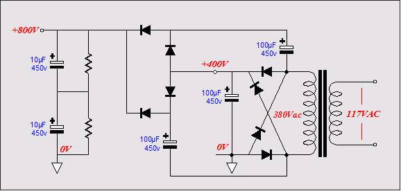
In contrast to the two preceding schematics, the above circuit uses a non-center-tapped power transfomer, which still establishes two B+ voltages.
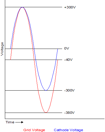
No matter how we get the two B+ power supply rails, we can use the extra voltage to good advantage. Remember that the big problem that cathode-follower-based output stages faced was getting a clean enough drive signal to drive them, as the drive signal amplitude must exceed the cathode's voltage swing.
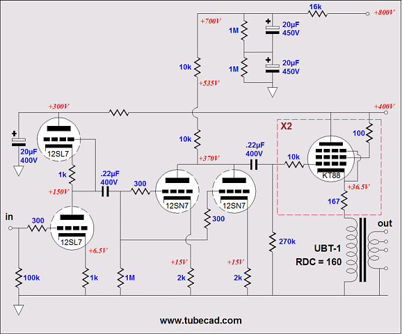
With an additional higher B+ rail for the driver stage, we can easily get the voltage swing we need without resorting to sonic dead ends, such as driver-stage bootstrapping. For example, in the schematic below, we see two KT88s being driven by two 12SN7 triodes, in a grounded-cathode amplifier configuration. The 12SN7 has an effective B+ voltage of 700V and 355V of cathode-to-plate voltage at idle. This setup allows the 12SN7 the greatest possible amount of voltage swing.
A simpler amplifier could be made...
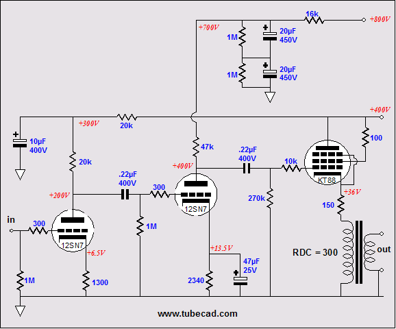
...although I doubt that the two 6SN7/12SN7 halves would offer enough gain. Thus, a better choice for input tubes might be a dissimilar dual triode, such as the 6DE7 and 6DR7. (Note the addition of the cathode resistor bypass capacitor on the 12SN7. I am not sure if it should be there or not. Experimentation is needed. Also note how both amplifiers use the output transformer's RDC to help cathode bias the the output tubes.)
In the next blog, we will look into push-pull cathode-follower-based output stages.
//JRB
|
|
|
|
TCJ Filter Design
The Tube CAD Journal's first companion program, TCJ Filter Design lets you design a filter or crossover (passive, solid-state or tube) without having to check out thick textbooks from the library and without having to breakout the scientific calculator. This program's goal is to provide a quick and easy display not only of the frequency response, but also of the resistor and capacitor values for a passive and active filters and crossovers.
TCJ Filter Design is easy to use, but not lightweight, holding over 60 different filter topologies and up to four filter alignments:
Bessel,
Butterworth,
Gaussian,
Linkwitz-Riley.
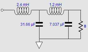
While the program’s main concern is active filters, solid-state and tube, it also does passive filters. In fact, it can be used to calculate passive crossovers for use with speakers by entering 8 ohms as the terminating resistance. Click on the image below to see the full screen capture.
Tube crossovers are a major part of this program; both buffered and un-buffered tube based filters along with mono-polar and bipolar power supply topologies are covered. Available on a CD-ROM and a downloadable version (4 Megabytes).
|


